MANUFACTURER'S SPECIFICATIONS
Frequency Response: 20 Hz to 20 kHz. +0, -0.5 dB.
THD: 0.1 per cent at rated output, 20 Hz to 20 kHz.
Input Sensitivity: Phono, 2.0 mV (adjustable); microphone 2.5 mV, high level, 250 mV; tape head, 2.0 mV.
Signal-to-Noise Ratio: Phono 1&2, 78 dB below 10 mV input; high level inputs, 90 dB below rated output.
Output Levels: Main, 2.5 V; tape, 0.25 V; headphone & line, 0.75 V into 8 Ohms or 2.5 V into 600-Ohm line; center channel, 1.25 V.
Tone Control Range: Bass, ±20 dB at 20 Hz; treble, ±18 at 20 kHz.
High Filter: 12 dB/octave slope above 7 kHz.
Low Filter: 12 dB/octave slope below 50 Hz.
Power Requirements: 120 V, 50&60 Hz, 45 W.
Dimensions: 16 in. (40.63 cm) W by 5-7/16 in. (13.8 cm) H by 13 in. (33 cm) D, behind panel.
Weight: 25 lbs. (11.34 kg.)
Suggested Retail Price: $649.00.
-------------------------------
Upon receiving this sample of McIntosh's popular C-28 preamplifier/control unit, our first reaction was that someone had mistakenly shipped us a power amplifier or an integrated amplifier, since we can recall no preamplifier unit we ever evaluated that weighed 37 pounds in its shipping carton, let alone 25 pounds even after extraction from a fully protected packaging arrangement which includes a separate inner carton, well isolated from the outer shipping carton.
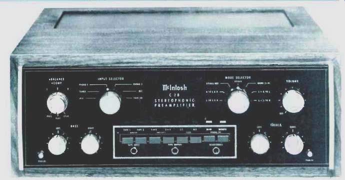
But, as thousands of McIntosh equipment owners probably know, ruggedness of chassis and construction is one of the things in which that company takes great pride. Some of that extra weight, to be sure, is accounted for by McIntosh's unique Panloc mounting design which eliminates the need for any shelf or bracket to support the C-28, for should you wish to custom mount it behind a cabinet panel, the hardware and brackets supplied will completely support the unit in such mounting arrangements. The front panel of the C-28, pictured here, extends beyond the largest width and height dimensions of the chassis, so that panel cutouts need not be made with great precision. Controls are symmetrically positioned on the face of the black, heavy glass front panel, with separate Bass and Treble control knobs for left and right channels along the bottom left and right extremes of the panel, together with controls for master volume (including power on/off switch), mode selection (seven positions of mono and stereo reproduction capabilities including reverse stereo and combinations of mono that permit feeding one channel to both speakers, two channel signals to a single speaker or a mono L+R mix to both speakers), six position program selection, and a dual concentric balance and compensation switch control arrangement which selects flat response, loudness compensation or "presence" mid-frequency emphasis. One input facility of the C-28 we have not encountered in some time is a Tape Head input which not only permits direct connection of tape playback to the pre-amp, but provides equalization as well. While we know of no tape transport systems currently sold for consumer use which are not equipped with their own preamplifier electronics (such tape playback devices were sold some years ago), this extra input facility does not impose significant penalties on the end price of the C-28, since the low-level preamplifier circuits used for phono double as a tape pre-amplifier (with a switched change of equalization curves). Selector and mode switches are coupled to tiny red illuminated dots, visible from behind the panel, which denote switch positions chosen. Eight rectangular pushbuttons, surmounted by rectangular, colored, illuminated areas above each, take care of two tape monitor circuits, tape-to-tape copying (from deck 1 to deck 2 or vice versa), low and high frequency cut-off filters, and main and remote speaker system turn-on (providing an accessory McIntosh SCR control unit is used in an installation). Below the pushbutton row are tape input and output jacks which parallel the rear panel Tape 2 connections (and disconnect them if front panel jacks are used) and a headphone jack for connection of stereo phones powered by the built-in headphone & line amplifier of the C-28.
The rear panel of the C-28 has no less than seven a.c. convenience receptacles, two of which are specifically intended for power amp line cord connections, with one of the remaining five an unswitched receptacle for turntable system connection. Two pairs of main and center channel output jacks are positioned above a four-contact receptacle labeled "speaker remote control" which accepts a plug from an aforementioned speaker switching accessory. Line outputs, tape outputs and high level inputs come next, with all low level input jacks positioned at the extreme right of the rear panel, far removed from the a.c. line receptacles, line cord, and line fuse at the left. A ground terminal completes the rear panel layout.
Additional controls are positioned atop the chassis, as can be seen in the overall chassis view. These secondary controls include low-frequency trim controls, phono 1 and 2 input level controls, output level controls, headphone level controls, and a power switch which controls the rear a.c. receptacles specifically designated for connection of your power amplifiers. By means of this switch, power amps can be turned off during headphone listening, for example. As we soon learned, these extra controls provide a refinement of control that is rarely found in pre-amplifier/control units these days, and their designation as "secondary" controls fails to reflect their importance in helping to match up all elements of a good high fidelity component system.
Circuit Features and Considerations
Each channel of the C-28 consists of four main sections: low level preamplifier, high level amplifier, active filters and headphone amplifier. A block diagram of the circuit is reproduced in Fig. 1.
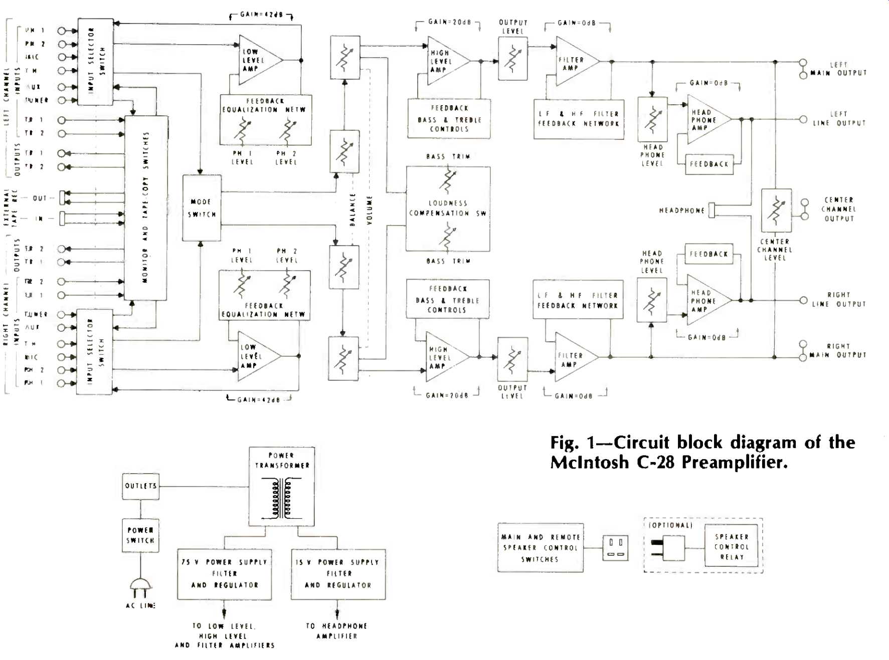
Fig. 1--Circuit block diagram of the McIntosh C-28 Preamplifier.
A four-transistor differential amplifier input circuit is used in the low-level preamp section. Equalization is applied by a negative feedback loop. Phono input sensitivity controls are also included in the negative feedback loop (rather than as simple input potentiometers) which permits gain reduction (if required, because of higher than average outputs from the phono cartridge selected) without degrading signal-to-noise ratios.
The high-level amplifier section has a gain of 20 dB and consists of a three-transistor circuit per channel with tone control action introduced via a negative feedback loop. Bass trim controls, presence, and loudness compensation circuits are positioned at the input of this amplifier section.
The filter amplifier sections utilize two transistors per channel in a compound emitter-follower configuration. In addition to the low-and high-cut 12 dB/octave filter components in this section, the filter amplifier also forms an active low-pass filter above 20,000 Hz. McIntosh subscribes to the philosophy that response beyond audible limits is neither needed nor desirable, and this filter design reduces noise outside the useful audio spectrum while maintaining flat response out to 20,000 Hz.
The headphone amplifier section delivers 0.75 Volts of signal into 8-Ohm headphone loads (approximately 70 milli Watts) or up to 2.5 volts into impedances above 50 Ohms.
Internal impedance is low enough (0.2 Ohms) so that relatively long shielded cables can be used without rolling off high end response.
The power supply of the C-28 consists of a 75 Volt supply and a separate 14 Volt supply for the headphone amplifier circuits. Actual output from the 75 Volt supply, following series regulation, Zener diode regulation, filters, and voltage dividing networks, is 18 Volts, used to power the low level circuits.
Laboratory Measurements
Response, in high level input positions, measured within 1.0 dB from 12 to 21 kHz, with the upper-3 dB point at 40 kHz. The lower -3 dB point could not be measured accurately. During these measurements, we discovered that the action of the bass trim secondary control is dependent upon the setting of the master volume control. In other words, with volume control at maximum, the bass trim control, like the loudness compensation circuits, has no effect.
Since most listening will, we presume, be done at lower settings of the master volume control, this circuit configuration does not practically reduce the effectiveness of this trim control, but we wondered why McIntosh chose to make it dependent upon that control. The presence setting of the compensation switch is also only effective at lower than maximum setting of the master volume control. It would seem to us that if presence control action is desired (and that is a big if depending upon what kind of music you like to listen to), it should be possible to achieve that slight midrange boost regardless of the master volume control setting.
As for distortion, it measured 0.05 per cent of any audio frequency from 20 Hz to 20,000 Hz for 2.5 Volt (rated) output signals (0.01 per cent at 1 kHz). Rated THD of 0.1 per cent was not reached until the preamplifier was delivering 14.0 Volts to the main output terminals.
Tone control action, depicted in the scope photo of Fig. 2, was extremely precise for each of the 11 steps of the bass and treble controls, with turnover points for both controls at approximately 1 kHz.
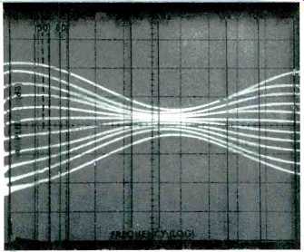
Fig. 2-Tone control range of the C-28.
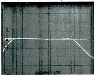
Fig. 3-High-and low-cut filter response.
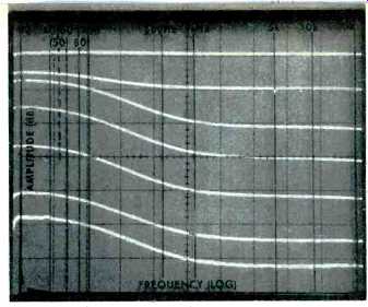
Fig. 4-Loudness compensation response.
High-and low-cut filter action is shown in the scope photo of Fig. 3. No passive RC filter network could ever deliver the sharp-cornered filtering which is so effectively accomplished by the active filters of the C-28. This is important because it means that, when using these filters, all musical energy up to around 7 kHz and down to 50 Hz will be reproduced with virtually no attenuation while the objectionable hiss, noise and rumble which prompted switching the filters on in the first place is very effectively attenuated beyond those cut-off frequencies. Action of the loudness control feature is shown at various settings of the master volume control (approximately 10 dB apart) in the storage scope photo of Fig. 4 and is seen to be loudness compensation of the type that does not include any high frequency boosting (in agreement with more recent hearing tests than those originally conducted by Messrs. Fletcher and Munson back in 1933). The presence control setting was found to provide approximately 5 dB of mid-frequency boost at mid-settings of the volume control.
Input sensitivity at high level inputs (for rated, 2.5 Volt output) measured 180 mV, with secondary output controls full open, and hum and noise measured exactly 90 dB below that output level, as claimed.
Master volume control tracking maintained channel balance within 1.0 dB all the way down to-65 dB relative to full clockwise setting.
Low Level Amplifier Performance
Phono input sensitivity was adjustable from 1.3 mV to 5.0 mV by means of the secondary controls, and we set them for a 2.0 mV input sensitivity as a reference for our other measurements. The availability of these input sensitivity controls, as well as of the output level secondary controls, makes it possible to "calibrate" one's system so that the loudness control circuitry has some validity. Too many manufacturers of amplifiers, preamplifiers, and receivers include loudness control circuitry without providing any means for its effective use. Gain of the power amplifier, output levels of program source equipment, efficiency of loudspeakers and even room characteristics all determine ultimate sound pressure levels heard by a listener from a component system. Since "flat" response is supposed to be referenced at approximately 100 dB SPL (the sound pressure level at which our hearing is relatively flat), the volume control should, in theory, be such that it causes that SPL to be delivered to the listener when the control is set fully clockwise. But how can that condition be achieved (except by pure accident) unless secondary controls are provided with which to calibrate the system? Obviously, McIntosh understands this problem and provides a neat answer in the form of those secondary controls. Additionally, of course, even if you never use the loudness feature, the controls permit balancing all your program sources with respect to each other so that you don't have to keep readjusting volume every time you switch from radio to phono, etc.
Phono overload occurred with an input signal level of 220 mV, well above any level likely to be encountered from a cartridge tracking a record groove. Hum and noise referenced to 10 mV of input signal was 78 dB exactly. RIAA equalization was accurate within 0.5 dB from 30 Hz to 10 kHz, while at 15 kHz it was down by nearly 1.0 dB.
Summary and Use Tests
It is difficult to make definitive "value for the money" statements regarding a preamplifier/control unit since, unlike the case of amplifiers or receivers, one does not even have a "dollars per watt" criteria upon which to base such conclusions. The audiophile who chooses to assemble the most "separate" of systems (one that consists of separate preamp, power amp, and program source components) invariably judges component value using other criteria, such as flexibility of controls, adequacy of switching features and, above all, the sound of the reproduced music. In all of these aspects the C-28 excels. There are more expensive preamplifier units on the market, many of them boasting multiple "zeros" after the decimal number used to specify distortion. There are even a few less expensive preamps available whose basic "specs" read better than those of the Mac C-28. Some have more controls and more light indicators.
Some even have meters. But few that we know of can produce as faithful and unaltered output signals from a variety of program sources as the McIntosh C-28. Here too is a component that is obviously built to last a long time, manufactured by a company that prides itself on the quality of parts and integrity of design for all its products. Having met a number of C-28 owners who wouldn't trade their units in for any other preamp around, we can now begin to understand their dedication to this long-lived model. Rumor has it that Mac may soon be coming out with a new preamp which might someday replace the older C-28. If that happens, the C-28 is likely to become another one of those hard to get high fidelity "classics" which actually increase in value with time.
-Leonard Feldman
(adapted from Audio magazine, Nov. 1976)
Also see:
McIntosh Model C-27 Stereo Preamplifier (Equip. Profile, Sept. 1978)
McIntosh Model MR-78 FM/Stereo, FM Tuner (Feb. 1977)
Mark Levinson JC-2 Straight-Line Preamplifier (Apr. 1976)
= = = =