Part. 1--New design approach provides sharper frequency control in the all-important audio midband
By Joe Gorin
GRAPHIC equalizers are popular audio accessories nowadays. They enable hi-fi buffs to adjust the frequency response of a stereo system to compensate for loudspeaker errors, room acoustic problems, and unsuitably balanced recordings and broadcasts. In essence, they are super tone controls that allow one to change small portions of the audio spectrum.
The 10-band graphic equalizer is the most popular type for home use.
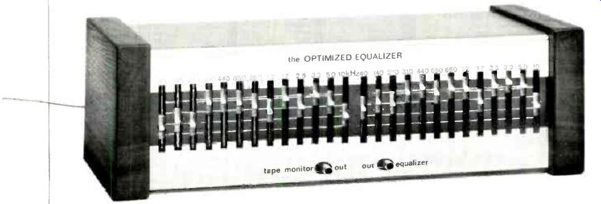
But a new design gives improved performance at low cost. It's called the Optimized Graphic Equalizer.
Now, instead of equalizing one-octave bands, half-octave control is available for the ten important midrange bands. Although bass and treble suffer somewhat (there are just three controls for these), the overall design allows for better control of frequency response. Additionally, an optional real-time analyzer can be incorporated into the circuit for equalization setup.
Design of the Equalizer. Human hearing is relatively insensitive to frequency response errors of less than 1/3 of an octave (called the "critical bandwidth"). This is why professional equalizers have 24 to 31 bands at approximately 1/3-octave spacings. But the critical bandwidth is actually narrower in the midrange than in the bass or high treble. Also, because the vast amount of musical information occurs in the midrange, this is the most important area for high-resolution (close band spacing) equalization. Normally, equalizers designed for home use have 1-octave spacings. In order to create an economical, but very effective equalizer, the Optimized Equalizer uses 1/2-octave spacing of bands in the midrange (for five octaves), a relatively wide band in the treble range, and two in the bass.
The most important function of an equalizer is the taming of two kinds of resonances-those with gain and those with loss. But a giant "hole" in the frequency response of a system (for example, a-20-dB "suckout" in a typical second-order speaker crossover) is practically inaudible. This is because the information in a narrow notch is small and masked by nearby signals. Furthermore, it isn't feasible to equalize a narrow notch. Practically speaking, you can't set the frequency and bandwidth close enough, and the phase relationships of the notch are so poorly controlled that, even if the frequency response were right, the actual signal waveforms wouldn't sound right.
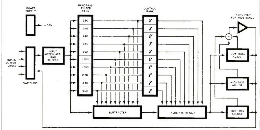
Fig. 1. Block diagram of the Equalizer. Midband frequency selection is made
by filter bank.
On the other hand, resonances that boost the frequency response are painfully obvious to the listener. A + 3-dB resonance adds more signal to a system than a-20-dB notch removes, and since it is an error of commission rather than omission, it "pops out" at you.
Also, the sound from such a resonance continues in the room long after the signal to the loudspeaker has stopped. An equalizer eliminates this problem, even if it isn't "right on" the frequency of the resonance, by reducing the energy that drives it.
Thus, it's more important for an equalizer to cut signals than to boost them. We chose to allow only + 3 dB of boost in the midrange bands, but a full 12 dB of cut. This is enough range to tame the worst resonances.
The bottom bass band of the Optimized Equalizer is just the opposite in range. It goes from -3 dB to + 12 dB, with the hinge frequency of the band moving higher with more boost. This band is thus optimized to improve the bottom useful octave of home loudspeaker response, usually stretching it from 45 to 65 Hz downward.
The mid-range band is placed at about 140 Hz in the Optimized Equalizer. This covers the space between the other bands and coincides with the typical midbass hump (the one that helps speakers sell so well in the hi-fi stores). Most persons will need to reduce the gain slightly at this frequency for improved accuracy, but a full ±8 dB is allowed because boosting this band can be fun, even if it is unrealistic.
The treble band covers the range above the last midrange band. Because of the large variations in loudspeakers and recorded material, ±10 dB is allowed on this band.
Circuit Operation. Figure 1 is a block diagram of the Optimized Equalizer. The midband frequency selection is done by the filter bank.
Since the filters have gain, the signal is attenuated at the input. This prevents even the largest signals at the tape monitor terminals of your amplifier from causing clipping of the filters. By subtracting three-quarters of the signal using the filter outputs, the result is a gain of -12 dB at the filter center frequency. Next, a variable amount of the filter output is added back to the signal. When the control is set to 0 dB, the added signal cancels the subtracted signal exactly for flat frequency response.
An important point about this block diagram is that the arrangement of the input attenuator and filter bank is exactly that required for a real-time analyzer (which will be discussed next month). The signal from the adder (which has gain to make up for the input attenuator) goes to a three-band circuit that is similar to those found in preamplifiers. The controls adjust the amount of feedback, and thus gain, in a particular frequency region.
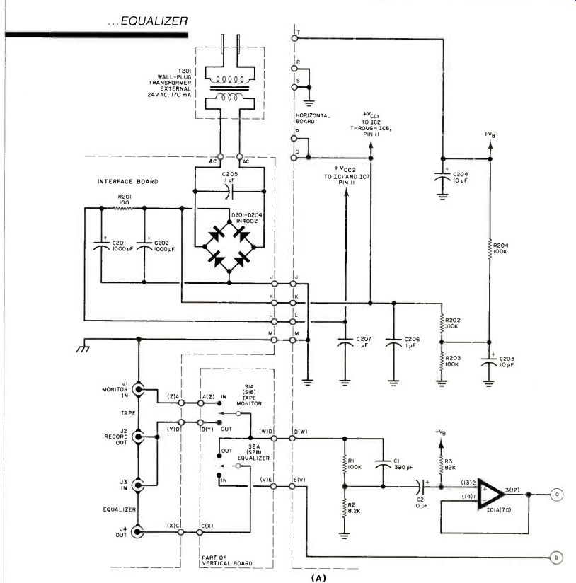
Figure 2 is the complete schematic for the Optimized Equalizer.
The power supply is a full-wave bridge rectifier (D201-D204) with a wall-plug transformer. The use of a remote transformer obviates the need for coaxial cables (without the penalty of hum pickup). Power to IC2-IC6 is unregulated because the power-supply noise rejection of these ICs is so good that hum pickup is trivial. However, power to IC1 and IC7 is passed through an RC filter to reduce hum by 18 dB because the circuits that use these two ICs are more sensitive to supply noise.
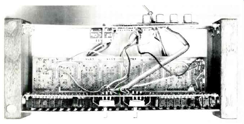
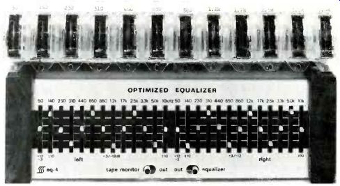
--------- Photo of the author's prototype showing internal arrangement
of the boards.
Resistors R202-R204 and capacitors C203 and C204 bias the ICs at 15 V. This double filter reduces the hum from the power supply to about 1 µV. The circuit could not be any quieter even with dual, fully regulated, power supplies (which would be much more expensive than the single supply used here). Resistors R1 and R2 form the input attenuator. Capacitor C1 reduces the attenuation at high frequencies where the filter bank cannot clip because the filters have low gain. Reducing the attenuation here allows the reduction of the gain, and thus noise, later on. Capacitor C2 couples the attenuated signal to IC1A, a gain-of-one stage that presents a high input impedance, but can drive the low impedance of the filter bank.
Op amps IC2A through IC4B are ten parallel filters. All have a bridged-T configuration. Let's examine IC2A as an example. At low frequencies, the input signal from R22 is blocked from IC2A by the high impedance of C22. At frequencies much higher than the filter's center frequency, the low impedance of C21 bypasses the signal from R22 into the low output impedance of IC2A, preventing its amplification. At the center frequency, though, the stage has a high gain. The signal from R22 is coupled through C22 to be amplified and inverted by IC2A. The output of IC2A is coupled back through C21. Due to the phase shift of the capacitor circuits and the op amp's inversion, this feedback signal is in phase with the direct signal. Resistor R23 controls the gain and positive feedback.
The signals from R55 and the even-numbered resistors, R34 through R52, are added at the input to IC1D. The filter outputs are all inverted at their center frequencies, which forms the subtractor in the block diagram. Controls R24 through R33 adjust the amount of signal added back in IC1 C, which implements the adder. The feedback around IC1 C rolls off the gain at high frequencies to make up for rolling off the attenuation with C1.
It thus allows better signal-to-noise ratio with flat response.
Op amp IC1B adds the last three bands to the equalizer. Consider first the bass band, controlled by R60. If it is set to full boost, then at low frequencies the input signal is applied to IC1B through relatively low-valued resistor R59, for little attenuation. Feedback comes from R62, R61, and R60; very large values imply little feedback and thus a large gain. If R60 is set to the other end, there is more attenuation and more feedback, for a net attenuation. At high frequencies, the bass control is bypassed by C26 and C27 and the midbass control is coupled in through C28. Above the midbass frequencies, C29 and C30 bypass the midbass control, and C31 couples the high-frequency control to IC1B.
The output of IC1B is coupled through C32 to eliminate the 15-V dc bias from the output. Resistor R72 increases the output impedance to about 600 ohms and prevents possible oscillation of IC1B due to highly capacitive connecting cables.
-------------TECHNICAL SPECIFICATIONS
OPTIMIZED EQUALIZER
Frequency Response: 10 to 80,000 Hz +1/-3 dB
Gain: 0 dB nominal
Distortion: Less than 0.02%, from 20 to 20,000 Hz at rated output
Rated Output: 0.5 V
S/N per IHF-A202: 82 dBA ref: 0.5 V
Maximum Input/Output: 9 V rms
Input Impedance: Approx. 100 kilohms in parallel with 390 pF
Output Impedance: Less than 600 ohms
Total controls: 13 bands per channel
Range:
Midrange: +3 to-12 dB nominal
Bass: - 2 to +10 dB nominal
Midbass: ±8 dB nominal
Treble: ±10 dB nominal
----------------------
-----------
PARTS LIST
Horizontal Board
C1 ,C101--390-pF, 5% capacitor C2, C32, C 102, C 123, C24, C 124, C 132, C203, C2O4,-10-µF, 25-V aluminum electrolytic
C3 through C22,C103 through C122--0.0022-µF, 5% polyester film capacitor C25,C125-0.001-µF, 5% polyester film capacitor C28,C128-0,22-µF, 10% polyester film capacitor C31,C131-0,01-µF, 10% polyester film capacitor C206,C207-0,1-µF, +80/-20% ceramic disc capacitor IC1 through IC7-RC4136 quad op amp
The following are 1/4-W, 5% carbon-film resistors unless otherwise noted:
R1,R101,R202 through R204-100 kilohms
R2,R102-8.2 kilohms
R3,R5,R103,R1O5-82 kilohms R4,R104-2.7 kilohms R6,R106-3.9 kilohms
R7,R107-120 kilohms R8,R108-5.1 kilohms R9,R109-160 kilohms R10,R110-7.5 kilohms R11,R111-240 kilohms R12,R112-11 kilohms R13,R113-330 kilohms R14,R114-15 kilohms R15,R115-470 kilohms R16,R116-20 kilohms R17,R117-620 kilohms R18,R118-30 kilohms R19,R119-910 kilohms R20,R120-43 kilohms R21,R121-1.3 megohms R22,R122-56 kilohms R23,R123-1.8 megohms
R54,R154-16.2 kilohms, 1% metal film
R55,R155-1.62 kilohms, 1% metal film R56,R156-24.9 kilohms, 1% metal film
R57,R157-36 kilohms
R58,R158-3 kilohms
R64,R71,R164,R171-5.6 kilohms
R72,R172-560 ohms
-----
-------
Fig. 2. The schematic of the Equalizer is shown here and on the facing page.
The left channel and power supply are shown. Part numbers for the right channel are the same but in the 100's or are shown in parenthesis on diagram (switches, ICs, etc.).
--------
Vertical Board:
C23-10-µF, 25-V aluminum electrolytic
C26,C27,C126,C127-0.1-µF, 5% polyester film capacitor
C29,C30,C129,C130-0.022-µF, 5% polyester film capacitor
The following are 1/4-W, 5% carbon-film resistors unless otherwise noted: R24 through R33,R63,R66,R69,R124 through R133,R163,R166,R169-50 kilohm slide potentiometer
R34 through R53,R134 through R153-33 kilohms R 59, R 62, R 65, R 67, R 159, R 162, R 165, R167-5.6 kilohms R60,R160-22 kilohms
R61,R161-9.1 kilohms R68,R70,R168,R170-1.5 kilohms S1,S2-Dpdt non-shorting switch
Power Supply :
C201,C202-1000-µF, 35-V aluminum electrolytic
C205--0.1-µF, +80/-20% ceramic disc capacitor
D201 through D204-IN4002 (or equivalent)
R201--10-ohm, 1/4-W, 5% resistor J1 through J4, J101 through J104Phono jack
T201--24-V, 170-mA wall-plug transformer (Dormeyer PS14201 or equivalent)
Misc.-No. 20 AWG bus wire (6'), ribbon cable (14 conductor, 71/2"), angle bracket (#6-32 threaded, one side, 8), #6 X 3/8" sheet metal screw (11), #632 X 1/4" machine screw (8), chassis, 16-pin DIP socket, 14-pin DIP socket.
Note: The following are available from Symmetric Sound Systems, 856 Lynn Rose Ct., Santa Rosa, CA 95404 (707-546-3895): complete
Optimized Equalizer kit (EQ-4) with unfinished walnut end panels at $100; complete
Optimized Analyzer kit (AN-1) at $60.
Also available separately: horizontal and vertical pc boards for Equalizer (EQ-4PC) at $17.; Analyzer and interconnect pc boards (AN-1PC) at $13.; slide potentiometers #EQ-4SP, $.95 each.
Quad op-amp IC #4136, $1.75 each.
Set of IC's for the analyzer #AN-11C, $6.00.
Wall plug transformer #EQ-4PT, $7.50.
Minimum order $10.00. All prices include shipping on prepaid orders in the U.S. Canadians add $4.00 shipping and handling. California residents add sales tax.
-------------------
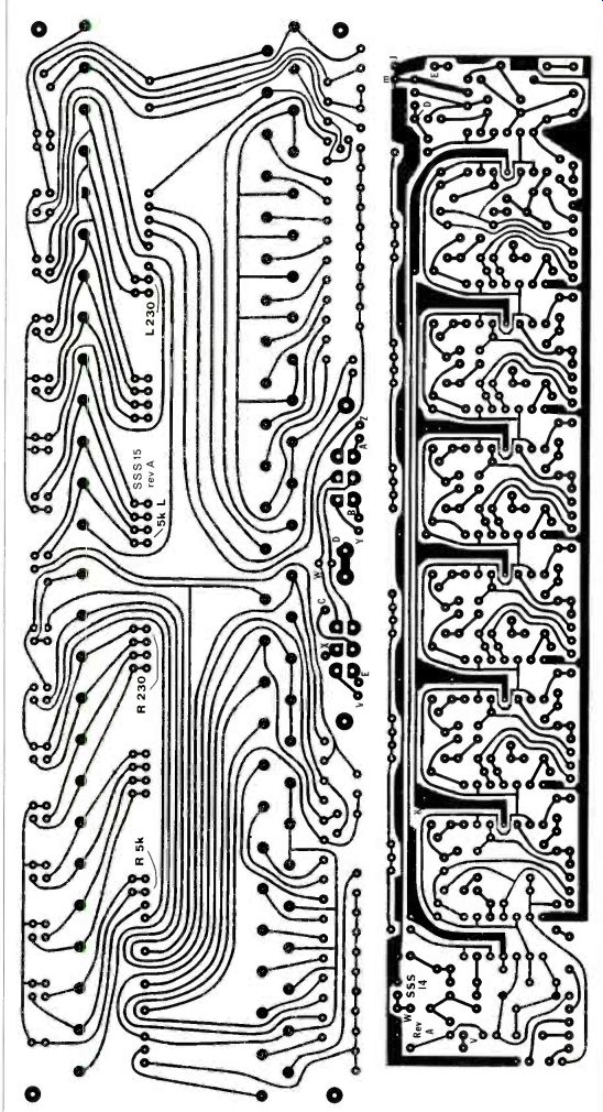
Fig. 3. Foil patterns for the Equalizer pc boards
----------
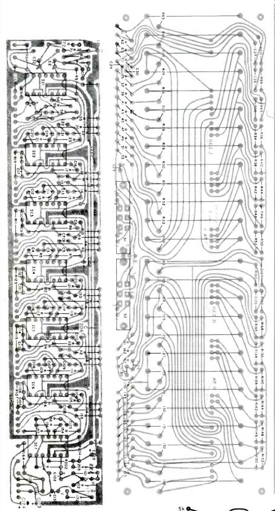
Fig. 4. Component layouts for the pc boards.
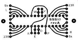
Fig. 5. Foil pattern for the connector board to the analyzer.
-----------
Construction. The Optimized Equalizer, except for the power supply input connectors and options, is built on two pc boards. The foil patterns for these boards are shown in Fig.3, and the parts placement diagrams are given in Fig. 4.
By placing all the controls on one board (the vertical board) and most of the remainder of the unit on the horizontal board, front panel space requirements are minimized. This makes for an efficient, compact assembly. The boards are connected together with #20-AWG bus wire between adjacent pads. The bus wire is stiff enough to make a rigid assembly of the boards, with easy access to both sides of boards for testing and experimenting.
Components should be soldered to the horizontal board first, in order of resistors, capacitors, jumpers, and ICs. Be careful to observe the index marking on the ICs and the polarity of the electrolytic capacitors. Next solder components to the vertical board-slide potentiometers first, then resistors, capacitors, and switches (observe the polarity on C123). To connect the boards, push #20-AWG bus wire or solid uninsulated wire through the pads in the long line on the vertical board from the back side, and solder to the pads. Taper the length of these pieces of wire from 3/4" on one end to 3" on the other end. Starting on the long end, and with the copper-clad sides of both boards facing each other, push the leads through the matching pads on the horizontal board, working your way to the short end. Bend the horizontal board, and thus all the wires, until it is perpendicular to the vertical board and flush against it. Solder all the wires.
Wire the switches, jacks, and boards together according to the schematic (wires A through E, M, and V through Z). Wire the power supply on a terminal strip, and connect it to the horizontal board (wires J through L). A foil pattern for an interconnect board is given in Fig. 5. One 16- and one 14-pin DIP socket are wired to this board.
The sockets are used to connect to the real-time analyzer, which will be covered in Part 2.
Because of the compactness of the pc-board assembly, many mechanical configurations are possible. In the prototype, the vertical pc board was attached to two pieces of walnut. The rear of an inverted "U" chassis was also attached to the walnut. The chassis provides marking for all the controls, switches, and jacks. Grounding the chassis to circuit ground shields the circuit from radio-frequency interference and electrostatic pick-up of 60 Hz and its harmonics.
Installation. Most component high-fidelity systems can accommodate signal processors, such as the Optimized Equalizer, through the tape-monitor loop. Connect the "tape out" or "tape record" output of your amplifier to the equalizer's input. Then connect the equalizer's output to the "tape in," "tape monitor," or "tape play" jacks of your amplifier. Switch the amplifier's tape monitor switch to "on" to enable the equalizer. The tape monitor function is replaced on the equalizer. Connect your tape deck to the equalizer as it had been connected to the amplifier.
Some amplifiers have separate tape source switches to enable you to play one source while recording another. In this case, you will have to use your tape source switch as your selector. Switch the selector switch to tape, so that the signal always passes through the equalizer.
Equalizer Adjustment. There are a number of different techniques available to adjust your equalizer; these vary in convenience, cost, and accuracy. Audiophiles with very good familiarity with live music can adjust the bands by ear to match their idea of the way the music should sound. A different technique is to use a test record, perhaps with the aid of a sound-level meter, to adjust the bands for flat response.
An easy way to adjust an equalizer is with a real-time analyzer. Although this can be a costly audio accessory, it's not in this case. The equalizer was designed to inherently contain much of the circuitry of the analyzer. In Part 2, we will describe the design, construction, and use of the analyzer.
With the high performance and build-it-yourself economies of the Optimized Equalizer/Analyzer, you can anticipate an impressive improvement in the sound of your system.
----- Part 2--An integral analyzer for accurately setting up the audio
equalizer in Part 1
In the first part of this article, we presented a new kind of equalizer circuit that offers high performance at an economical cost. In this second part, we will describe a Flatness Analyzer, an accessory you use to rapidly and accurately adjust the equalizer. The details follow.
Circuit Operation. Figure 6A is a block diagram of the equalizer/ analyzer combination (part of which is identical to Fig. 1). The analyzer plugs directly into the equalizer. Figure 6B is a block diagram of the equalization test procedure.
Here's how the Flatness Analyzer tests one channel (the right) of the Optimized Equalizer. Pink noise is applied to the right-channel input of the equalizer. The equalized output of the right channel is then fed through an amplifier and speakers into the room. From here, the microphone picks it up.
The signal is then amplified by the microphone preamp and applied to the left-channel input of the equalizer, as well as two filters in the analyzer. The outputs of these 12 filters drive simple biased-diode detectors and a bank of 12 meters to show the deviations from flatness. If the system response is flat, all meters will have equal deflections. The output of the left channel is grounded to prevent the amplified microphone signal from passing back out through the left speaker and perturbing the measurements or causing oscillations.
To test the left channel, the interconnecting plug is reversed and offset in its socket, and the above procedure is repeated with left and right channels reversed.
Figure 7 is the schematic of the analyzer. Integrated circuits IC2 and IC3 constitute a digital white-noise generator. The circuits in IC3A and IC3B form a square-wave oscillator with an output frequency of about 100 kHz. This clocks 18-stage shift register IC2, which keeps shifting the output of IC3D, the exclusive-OR function of the 14th and 17th stages of the shift register.
These taps (14 and 17) are chosen so that the register outputs random ones and zeroes; it only repeats after going through all but one of the 21' possible states. This is called a pseudo-random sequence generator (since it repeats, it isn't truly random). Its output spectrum is very white if you pass the digital output through a low-pass filter. Integrated circuit IC3C and its associated components ensure that IC2 cannot get locked up in the all-zeroes state.
Components R29 through R32 and C20 through C23 are a pinking filter. The gain vs. frequency of this network falls off at 3 dB per octave on the average, about half as fast as a single RC filter. The noise is amplified by IC4B and rolled off at high frequencies to compensate for the increased gain of the testing channel at high frequencies (due to the reduction in input attenuation as explained previously). The output is ac coupled with C25, and its level is controlled with R32. The level could be controlled with the stereo's master volume control, but having a control on the analyzer is a real convenience. The signal from the level control now passes to the channel under test.
The stereo speakers convert the noise to sound, which comes back for analysis through the microphone, MIC/. A small electret is used here, which has typical accuracy of ±1 dB with help from the preamp, IC1B. This stage provides a gain of 27, and C33 and R44 tame an upper-midrange peak that is common to most inexpensive electret microphones.
The microphone signal is further amplified in IC1A and passed through R48 and C32 to the testing channel's filters. Resistor R48 is provided as protection in case the input to the equalizer is not disconnected.

Fig. 6B. Block diagram of the equalization test procedure with the analyzer and equalizer connected.
Besides the ten filters in the equalizer, IC1C and IC1D filter the frequencies around 40 to 100 Hz and 140 Hz to help adjust the bottom bands of the equalizer.
The filtered signals from the equalizer are ac-coupled by CI through CIO (to remove the dc components) and detected by D3 through D12. To minimize the errors due to the on voltage of these diodes, a small current is passed through D15 and buffered by IC4A to offset the positive side of the meters by approximately the diode on voltage. As a result, the meters respond to the average value of the noise level, which is a much more accurate parameter than the peak response frequently used in such an analyzer.
The outputs of IC1C and IC1D are passed through RC filters R18, R19, R24, and R25 and C12 and C16 to reduce the fluctuations of the bottom band meters and to reduce the gain, in order to make up for the effect of the attenuator at the input of the testing channel on the ten other bands.
Resistor R17 and diode D16 provide a + 9-V supply for the microphone and white-noise generator, and also supply bias for IC1.
Switch S1 allows the response of the analyzer to be observed without the speaker-microphone link, to see how flat it is. This calibration permits adjustments to be made that will provide compensation for component tolerance errors, especially in the meter sensitivities (±1 dB) and pinking-filter components.
---------------
Fig. 7. Schematic of the circuit in the analyzer.
PARTS LIST
C1 through C10,C12,C13,C16,C17,C24, C30, C32--10-µF, 25-V aluminum electrolytic
C11,C28--0.1-µF 50-V ceramic disc
C29--10-µF, 25-volt electrolytic
C14-0.0047-µF, 5% polyester capacitor
C15,C18,C19,C25-0.1-µF, 5% polyester capacitor
C20--0.022-µF, 5% polyester capacitor
C21--0.0068-µF, 5% polyester capacitor
C22,C26,C34-0.0022-µF, 5% polyester capacitor
C23-0.001-µF, 5% polyester capacitor
C27--24-pF, 5% capacitor
C31-not used
C33-39-pF ceramic disc capacitor D1 through D15-1N4148 diode D16-9.1-V zener (1 N5239 or 1 N960) IC1-RC4136 quad op amp IC2-CD4006 18-stage shift register IC3-CD4070 quad ex-OR gate IC4-LM358 dual op amp M1-M12-200-µA 1-kilohm edgewise meter MIC1-Electret microphone element P1-16-pin DIP plug The following are 1/4-W, 5% carbon-film resistors unless otherwise noted: R1 through R10,R40-470 ohms
R11,R39,R46,R49-1.5 megohms
R12 through R16--Not used R17,R20,R26,R28,R48--2.2 kilohms
R18,R19,R50-8.2 kilohms
R21-300 kilohms
R22,R34,R43-3.9 kilohms
R23-39 kilohms
R24,R25-11 kilohms
R27-62 kilohms
R29-270 kilohms
R30,R37,R38-150 kilohms
R31,R41-47 kilohms
R32,R33,R36,R44,R47-15 kilohms
R35,R45-50-kilohm potentiometer R42-100 kilohms S1-Spst slide switch Misc.-Pc board for analyzer, press-on rubber feet (4), 16-wire ribbon cable, jumper wires, etc.
Note: The following are available from Symmetric Sound Systems, 856 Lynn Rose Ct., Santa Rosa, CA 95404 (707546-3895): complete Optimized Equalizer kit (EQ-4) with unfinished walnut end panels at $100; complete Analyzer kit (AN-1) at $60. Also available separately: horizontal and vertical pc boards for Equalizer (EQ4PC) at $17; analyzer and interconnect pc boards (AN-1PC) at $13; slide potentiometers (#EQ-4SP) at $.95 each; quad op amp IC #4136 at $1.75 each; set of ICs for analyzer (#AN-11C) at $6.00. Wall-plug transformer (#EQ-4PT) at $7.50. Minimum order
$10.00. All prices include shipping on prepaid orders in the U.S. Canadians add $4.00 shipping and handling. California residents, add sales tax.
---------------
Fig. 8. Foil pattern for the analyzer pc board.
Fig. 9. Foil pattern for connector board to equalizer.
==============
WHAT'S WRONG WITH THE FLATNESS ANALYZER? According to traditional thinking, there is quite a bit wrong with the analyzer. First, its output devices are meters. Unlike bar-graph LEDs, meters cannot be easily read from far away. They are also slow and cannot show the dynamics of music well, due to mechanical inertia. But we are not building a music analyzer; we are building a flatness analyzer. It is designed to be placed next to the equalizer so that the controls can be adjusted while watching the meters. Only the microphone needs to be usable from a distance, and it comes with a long cord.
The slowness of the meters is in fact desirable because it evens out the fluctuations in the noise levels. Actually the meters act as filters without extra components to do that filtering (except in the lowest bands, where the fluctuations are slow enough that additional filtering is desirable). However, the most important reason for using meters is that they give better resolution and "feel" for that signal level.
Their fluctuations can be averaged visually much faster and more accurately than LEDs, especially in designs with 2.5 dB/step LED resolution.
Next, the Flatness Analyzer will not analyze music. Since the signal levels in the testing channel must be adjusted to drive the meters appropriately, this channel cannot be used to process music. This precludes the fascinating light-shows of some analyzers, but it is necessary for the economy of reusing the equalizer's filters.
We're out for performance here, not a show.
Finally, the Flatness Analyzer does not have a top-end meter to help adjust the equalizer's 10-kHz control. One is easily added, but it is not worthwhile for a number of reasons. First, a microphone that has even marginally predictable response in the top octave will cost more than the entire equalizer/analyzer combination; using it would produce the worst kind of diminishing return on your investment. Secondly, recorded music in the top octave is notoriously variable in relative level due to varying microphone techniques and engineer's tastes. Finally, all speakers, microphones, musical instruments and ears are extremely directional at high frequencies.
Unlike the situation at lower frequencies where most of the signal you equalize has been reflected from room boundaries; at high frequencies, you would be equalizing the direct signal from the loudspeakers.
The desired ratio of this signal level to the reverberant measured levels at other frequencies is not well controlled.
Thus, no one equalizes for a flat high end. Rather, they try to accomplish some smooth roll-off. The author strongly recommends setting this band by ear and resetting it (and perhaps the top two or three narrow bands slightly) according to the particular piece of music being played.
===============
Construction. Figure 8 is the foil pattern for the analyzer pc board, and Fig. 9 is the foil pattern for the interconnection pc board. A component-placement diagram for the analyzer is given in Fig. 10.
Solder all components to the board, except the slide potentiometers. Don't forget the two jumpers.
Carefully orient the ICs, diodes, and electrolytic capacitors according to pin number or polarity. Integrated circuits 1C2 and 1C3 are CMOS, and thus static-sensitive; so don't remove them from their conductive packaging until you are ready to install them. Then discharge yourself, your soldering iron, and the pc traces to ground.
Connect the microphone element, MIC1, to the shielded pair cord and solder the cord to the appropriate pc board holes-red wire for positive, white for signal, and shield for ground. Connect a stiff piece of wire over the shield and solder to the two holes right behind it to act as a strain relief.
The connection to the equalizer is through a DIP plug. Cut a standard DIP-plug to DIP-plug 16-wire cable in half and solder the unterminated wires to the appropriate pads of the DIP pattern on your board (the wires will alternate sides). Or just install a whole DIP-plug right in the pattern. Pass the wires across R35's position, and then mount R35 over them as a strain relief. Also mount the other slide potentiometer in its proper location.
In the prototype, the bases of the edgewise meters were glued to the pc board and wired with short jumpers. It is a good idea to use stick-on rubber feet to prevent shorting to the chassis of the equalizer or scratching it during use.
Since the analyzer is a sophisticated accessory and not for display, to save effort and expense, you need not put it in a fancy chassis.
Adjustment and Use. Using the Optimized Equalizer and the Analyzer combination is easy because all the information you need is right in front of you at all times.
With the power off, connect the equalizer outputs to your stereo. Do not connect the equalizer inputs to anything. Connect the analyzer to the equalizer and turn the slide pots to OFF. Set the TEST switch to EQ and the EQUALIZER switch to IN. Set all the equalizer controls to 0 dB. Place the measuring microphone at your favorite listening location. Apply power to the equalizer/analyzer and your stereo.
Adjust the mike gain upwards until there is significant deflection of some of the meters. This point shows how large the room noise is.
Back down on the gain until there is no more than 10% deflection on any meter. Now slowly advance your noise-level control and stereo-volume control until you are getting an average of over 70% of full deflection on your meters. Depending on the ambient levels in your room, this is likely to be relatively loud.
Adjust the bands of the channel under test by reducing the level of the band corresponding to the meter with the highest deflection. After you have adjusted a few bands this way, continue by moving the bands either up or down to come as close as possible to uniform deflection of all bands. Adjust the noise level as necessary to keep the aver-age deflection at about 70%. The noise source, being pseudorandom, audibly repeats every 1.5 seconds, and the meters will show this periodicity. When fine tuning, visually average the motion during this interval. When the result is close to flat, switch the TEST switch to CAL, adjust the MIKE GAIN for 70% average deflection, and observe the errors of the test system.
Then switch back to EQ and fine-tune the equalizer to match the CAL response, which will be slightly different than truly flat. Then turn everything off, switch the connection from the analyzer to the equalizer, and repeat for the other channel.
Then remove the analyzer and connect the equalizer normally.
Hints on Equalizing. Over the long term, the sound from your system will be exceptionally smooth and accurate. But be wary of short-term reactions. After listening so long to the errors that your system and room make, your mind gets accustomed to these distortions of reality and expects them. Thus, any change toward either more or less realistic sound is initially perceived as unnatural. Also, the equalization technique given will reduce the overall level somewhat. Unless you compensate by increasing the volume control setting, you are likely to initially consider the sound to be poorer when equalized.
But give yourself about 15 minutes with your de-resonated stereo and then switch to unequalized.
You will notice a hollow, boxy sound that you missed before because you were so used to it. Now simply switch back to equalized sound and you will find some really fine listening.
Fig. 10. Component layout on analyzer pc board.
===========
TESTING THE EQUALIZER/ANALYZER
-----p34 Boost and attenuation effects of the ten filter points.
The concept of having the analyzer use some of the circuits in the equalizer is an interesting one and makes for economy in achieving both analysis and equalization.
In addition, the recognition that a limited amount of boost and much more "cut," are required for room/speaker equalization is something we have not seen discussed before. It differs sharply from conventional practice, which provides symmetrical (more or less) boost.
The measured characteristics of the various filters in the analyzer and equalizer confirm the statements made in the article.
It is interesting to note that using only the extreme controls (40 Hz and 10 kHz) one can simulate quite well the effect of a conventional tone control system. The distortion of the equalizer was negligible and well within the stated limits. The noise (which was below our measurement limit)
appeared to meet the claimed performance comfortably.
Following the instructions, we used the system to equalize a stereo music system.
It would be helpful if the meters could be marked to match the corresponding slider controls; we had to use some "cut and try" methods in doing the equalization, but the end result seemed to be reasonable. According to a spectrum analysis of the "pink noise" from the system, it is not quiet pink.
However, since one uses the meters to read the noise spectrum as well as the equalized acoustic spectrum, this error is of no importance.
---Julian Hirsch.
===============.Source: Computers and Electronics--Experimenter's Handbook (1984)
Also see:
Build ‘LIDITH' -- A 3½-Digit Digital Thermometer
Build a Diode Temperature Probe