AMAZON multi-meters discounts AMAZON oscilloscope discounts
INTRODUCTION
Drafting tools used in electronic drafting and design are the same as those for all other fields of engineering and design work. If a difference exists, it is in the level and complexity of drafting technology and the variety of drafting and design techniques available, ranging from plastic taping and preprinted transfer materials to computer-aided design (CAD) systems. The traditional manual drafting techniques and tools are still used throughout the industry, however. Therefore, as an aspiring electronic technician, drafter, designer, or engineer, you need to have a firm grasp of procedures and be familiar with these tools. Every engineering office uses the equipment described in this section, with varying degrees of sophistication in the design process. Even where CAD systems have replaced manual methods, the simple and essential drafting tools can still be found—pencils, compasses, dividers, templates, drafting machines, drafting tables, and drawing storage cabinets. The simple lead holder and the complex electric light pen are of equal importance to the total drafting and design process.
This section is meant to be used as an overview of drafting equipment, instruments, and materials. Equipment includes drafting boards, T squares, triangles, templates, and computer-aided design hardware. Instruments are precision manufactured drawing tools, such as compasses and dividers in all their variations. Drawing mediums and related support items (drafting paper, grid underlays, preprinted title blocks, and transfer drafting aids) are drafting materials.
Drafters and designers must know how to use their equipment, instruments, and materials to be able to communicate effectively by lettering and linework. Both the user and the originator of a drawing must understand the procedures, conventions, and concepts used in the drawing. In electronic drafting and design, symbols, linework, projection procedures, and notation must be assembled according to standardized drafting conventions.
EQUIPMENT
The most important and conspicuous piece of equipment found in any drafting room is the drafting table. Originally, all drafting was done on simple flat-surfaced wooden drawing boards. Normally, one or more edges were cut as straight and square as possible, making a straight edge for the drafter to guide a T square. Today board sizes range from the hand-carried versions of 9 x 12 in. to the large-format, stand-alone tables commonly found in industry and the classroom. FIG. 1 shows a modern drafting table. This table is vertically adjustable and can be tilted to any comfortable angle. FIG. 2 shows a large 3 ½ x 8 ft automatically adjustable drafting board. Whatever the size or material used for a drafting table, the table surface must have a pliable cover. This surface can be a plastic or vinyl covering that permits drafting without destroying the table surface or marring the drawing medium (paper, plastic film, cloth).
Light tables are also used throughout the electronics field to prepare printed circuit artwork, draw pictorial illustrations, and trace projects. A light table is shown in FIG. 3. Normally the drawing surface is an opaque glass or plastic sheet that scatters the rays from the light source. FIG. 4 shows a modern drafting station and reference desk. FIG. 5 shows a small portable table with a light for tracing and doing artwork. This table has a built-in grid pattern as part of its drawing surface. A grid pattern covering can also be applied to tables w: lights.
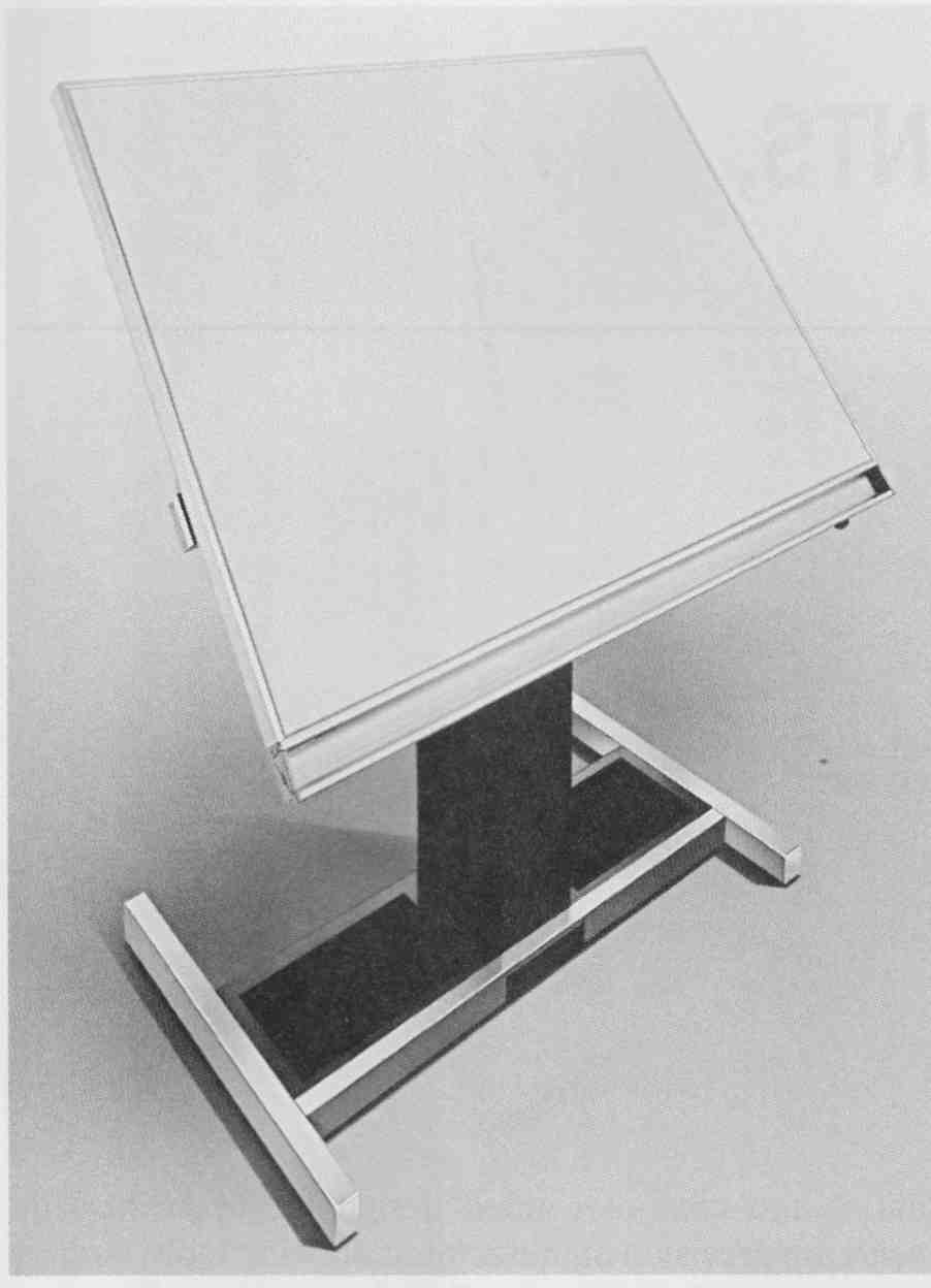
FIG. 1 Modern steel drafting table. (Courtesy Hamilton Industries)
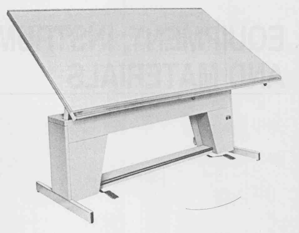
FIG. 2 Large-surface, high-quality metal frame drafting board. (Courtesy
Hamilton Industries)
A grid pattern can greatly aid the engineer, de signer, or drafter in preparing block, logic, schematic, or wiring diagrams. A grid system in electronic drafting and design is especially beneficial since most electronic drawings are two-dimensional diagrams composed al most exclusively of vertical and horizontal lines. Drawings and sketches to be digitized on a CAD system require the use of a grid system. Grid patterns are also essential for the proper alignment and layout of printed circuit boards.
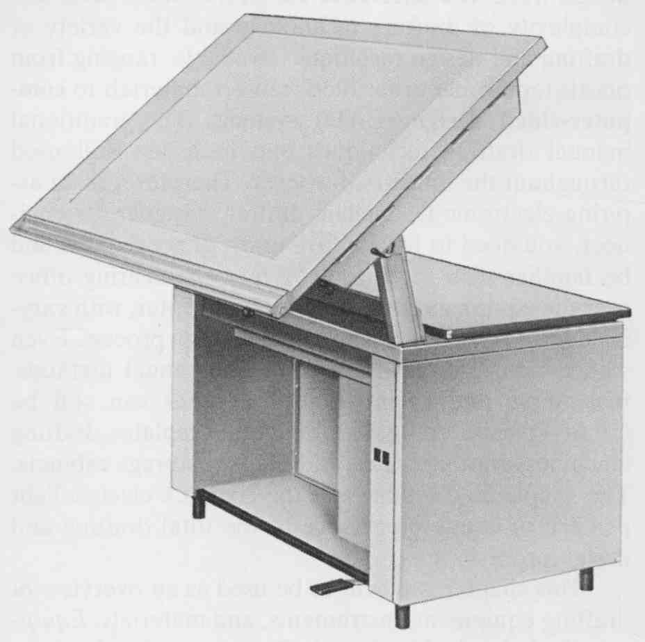
FIG. 3 Light table. (Courtesy Hamilton Industries)
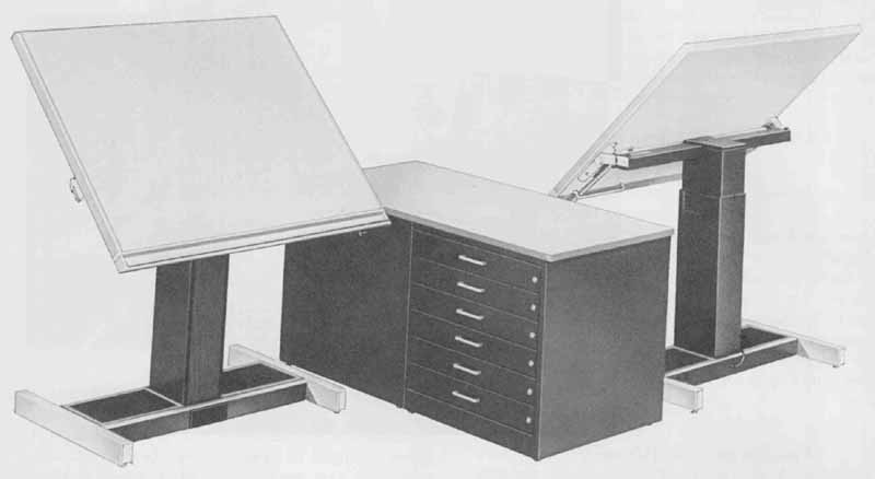
FIG. 4 Modern drafting stations, reference desk, and drawing storage.
(Courtesy Hamilton Industries)
CAD Equipment
CAD equipment is normally referred to as hardware. Hardware includes all types of computer and drafting equipment associated with a computer-aided design: computer screen, keyboard, electronic pen or mouse, digitizer tablet, mainframe or local processor, mass storage components (such as a hard disk), and hard-copy device (printer or plotter) ( FIG. 6).
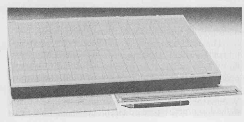
FIG. 5 Grid-surfaced portable light table. (Kroy, Inc.)
The CRT, or cathode-ray tube, is the television type of monitor used to view a project as it is drawn. The software (program) is used to relate commands from the operator to the systems hardware. Commands can be entered on the keyboard. The digitizer tablet or table is used to convert existing graphic data into a digital form understood by the computer. A graphics/data tab let is shown in FIG. 6.
The pen plotter converts the computer’s digital data into graphic data by plotting the drawing on paper or drafting film. In FIG. 7, the pen plotter illustrated is a drum-type plotter.
The two most important pieces of computer hard ware in a CAD system are the processor and the mass storage system. In a PC-based drafting system, the processor is built into the workstation. In more sophisticated systems, the processor is a stand-alone centralized computer unit capable of handling multiple stations as well as performing non-CAD du ties, such as business and word processing applications. In CAD engineering workstations ( FIG. 6), the processor is separate from the keyboard and monitor. The storage medium of a CAD system today is generally a hard disk, often with one or more gigabytes of space.
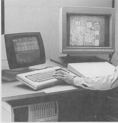
FIG. 6 Electronic Design / CAD system. (Prime Computervision)
Storage and Reproduction Equipment
After a project is drawn, regardless of the method, it must be stored and reproduced. CAD electronic drawings are plotted on pen or photoplotters. Reprographics, computer-stored design data for quick reproduction, of ten replaces cabinet storage of original drawings.
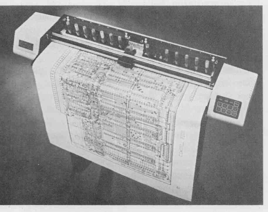
FIG. 7 High-speed 14-pen plotter. (Courtesy Houston Instruments)
Storage
Frequently, drawings are stored as paper prints and originals. Multiple-drawer cabinets, like the one shown in Fig. 18, as well as tube storage systems, all require expensive, cumbersome equipment that takes up valuable office space. The graphic data must be cataloged and physically available to several departments. This method of storage is time consuming and requires a good deal of office space.
Reprographic systems can eliminate the need for bulky storage of original drawings. For example, drawings can be stored on microfilm. Computer graphics systems enable you to reproduce design data stored on disk or tape. Another form, reprographics, uses 35-mm micrographic aperture cards (design data cards).
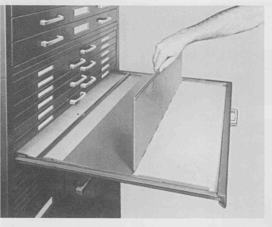
FIG. 8 Hamilton Unit System File drawing storage cabinet. (Courtesy
Hamilton Industries)
The design data system can be used with traditional manual drafting techniques or computerized procedures. Design data card systems such as the one developed by the 3M Corp. allow access to 1,300 design drawings in less than 7 ½ in. of space in a desk drawer. When a new or revised drawing is checked and ready for release, it is taken to a processor camera, or film plotter ( FIG. 9). In seconds, a master data card—an accurately reduced version of the original—is produced. This card is correct in every detail but is smaller and easier to use and reproduce than an original drawing. Multiple copies of the data card are then made from the original for distribution to the users. The users can review the drawing with a display device at their work stations. Many of the industry-provided drawings in the text were reproduced from design data cards.
Reproduction
Traditionally, the blueprint machine was used to make multiple prints of drawings. The term blueprint is not quite accurate today since blueprints are actually whiteprints, or what may be called blue-line prints. A whiteprint machine, shown in FIG. 10, is a more accurate description because most, if not all, reproduction with this method involves developing a print with blue lines and white background, not the opposite.
For a drawing completed on a CAD system, the user must be able either to reproduce the drawing from a hard-copy device like a photocopier or to plot the drawing with a pen plotter, shown in FIG. 11 and FIG. 7, or a photoplotter, shown in FIG. 12. The pen plotting method allows the production of an accurate original every time the drawing is replotted. Multiple copies can then be made from a white printer or from input to a data card system. The beauty of the CAD system lies in the ease of reducing or enlarging the originals and reproducing originals on a wide variety of drafting paper.
Aperture data cards enable the user to make fast multiple photoprints with several reduction and enlargement printout options. The manually operated, low-volume photoprinter shown in FIG. 13 allows the opera tor to print a drawing on various kinds of paper and instantly switch enlargement scales. The print paper is manually fed into the front of the printer, and the viewing screen allows easy monitoring.
T Squares, Parallel Bars, and Drafting Machines
Three methods of drafting—CAD, drafting machine, and parallel bar—are used in industry.
Originally, the primary straightedge device used in drafting was the T square, shown in FIG. 14. This piece of equipment is still used in some drafting classes and for personal drafting. It is said that “if you can draw with a T square you can draw with anything” because the T square is the most difficult of all straightedge drawing devices. If you must learn on a T square, then be comforted that once you master it other straightedges will be easier. The T square itself is not so difficult to use, but it is the easiest to misalign of all straightedge devices. The bar portion of the T is placed along the edge of a drafting board or table. Parallel horizontal lines are drawn with the length of the T square, and parallel vertical lines are drawn with a triangle placed on the T square. Obviously, if the T square and the table edge are not aligned properly, the linework will be inconsistent.
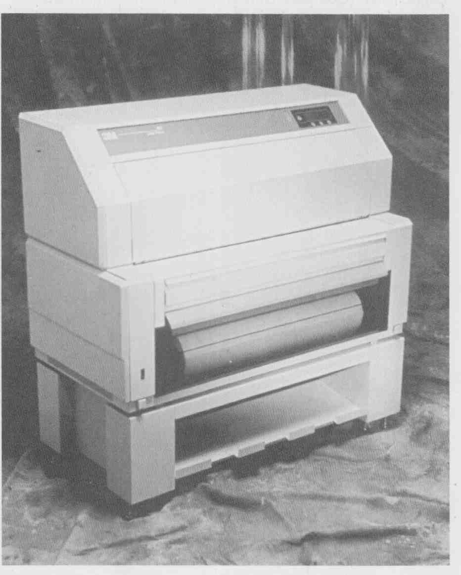
FIG. 9 Film plotter. Converts CAD-generated engineering drawings directly
to 35-mm aperture cards. (Courtesy 3M Corp.)
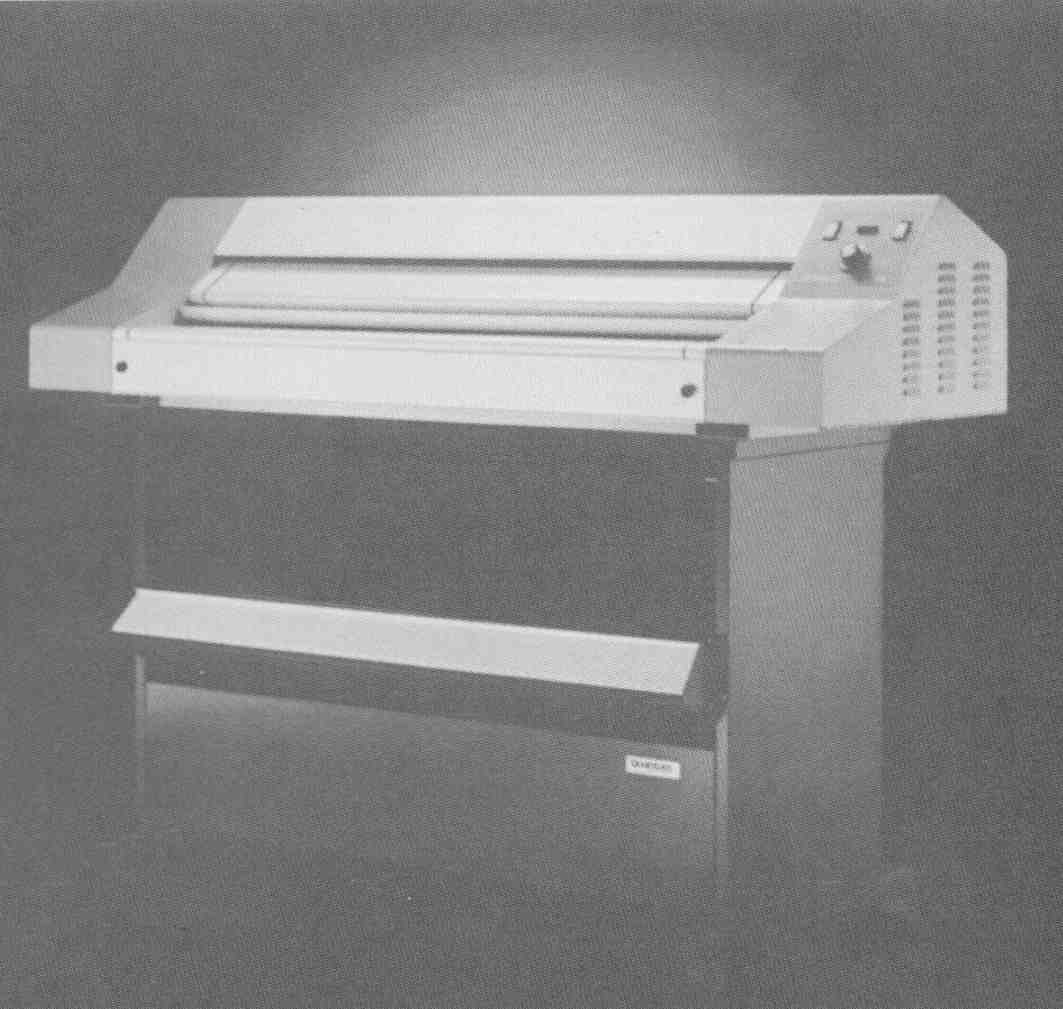
FIG. 10 Non-ammonia white printer. (Bruning)
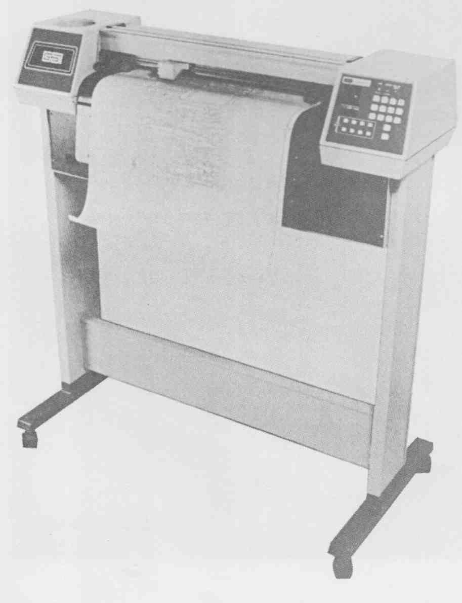
FIG. 11 Check plotter—low cost, large area, on-line check-plotting
capabilities. (Courtesy Gerber Scientific Instrument Co.)
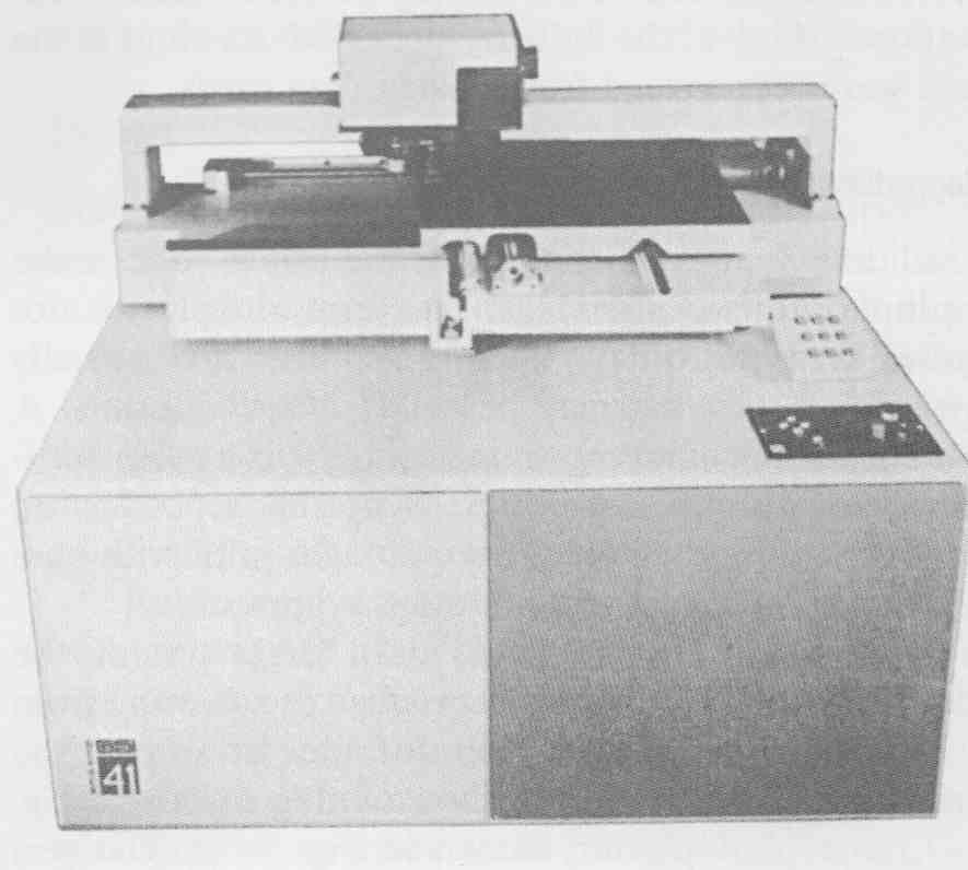
FIG. 12 GSI photo-plotter. (Courtesy Gerber Scientific Instrument Co.)
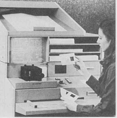
FIG. 13 3M enlarger—printer. Makes prints from aperture cards on vellum,
paper, or printing plates. (Courtesy 3M Corp.)
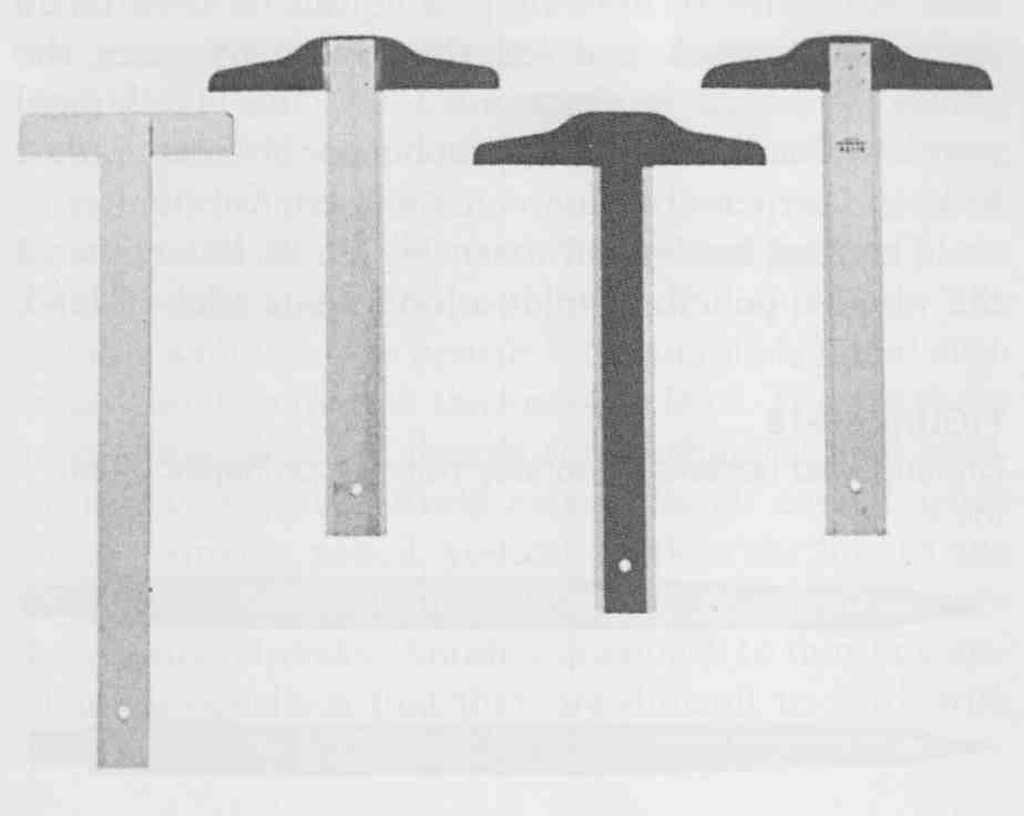
FIG. 14 Wood and plastic-edged T squares. (Courtesy Pickett)
The parallel bar, or straightedge, is found through out industry, since it is an excellent tool for drawing long horizontal lines. The parallel straightedge is attached to the drafting table by a series of cables and pulleys. It remains parallel or at a preset angle to the drafting table as it is slid up or down the table surface. Parallel straightedges are excellent for electronic drawings, where long, straight parallel horizontal and vertical lines make up most of a drawing.
The drafting machine comes in two standard versions, the drafting arm type, shown in FIG. 15, and the track type, shown in FIG. 16. The track type is the most accurate and costly. Drafting machines are mounted to the drafting tables, as shown in these figures. Drafting machines take the place of triangles, protractors, and scales. The control head can be rotated to any angle and set by pushing a button or locking the head. Most drafting heads automatically lock in 15-degree increments and must be hand-locked for intermediate angles. When you use the drafting machine—or, for that matter, any drafting straightedges—avoid dragging the equipment across the drawing. Always lift the equipment above the paper to avoid smearing the drawing.
Proper lighting is essential for relaxed, unstrained work with manual drafting techniques. FIG. 15 shows an arm-type drafting machine with a lamp attached to the board. Lighting requirements are considerably different when a CAD system is used because the CRT screen is easier to read if it is shaded from external light sources.
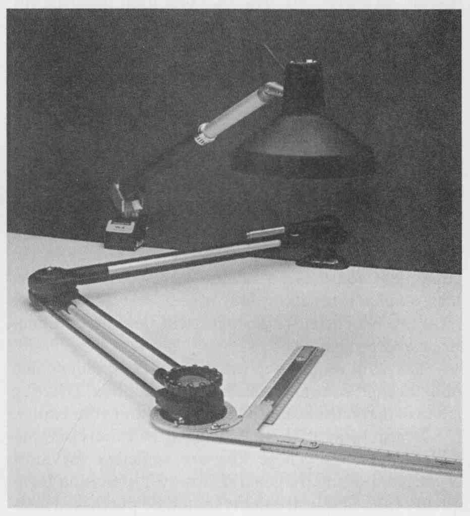
FIG. 15 Arm-type drafting machine. (Courtesy Picket Co.)
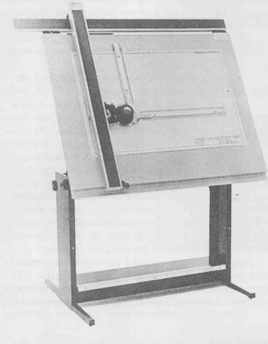
FIG. 16 VariTilt drafting table with track-type drafting machine. (Courtesy
Keuftel & Esser/Kratos)
General Equipment
Traditional manual drafting requires a variety of small tools and equipment, which are shown in FIG. 17. Special templates, inking pens, stick-on symbols, and so on, are used throughout the electronics industry. This section provides an overview of the wide range of equipment on the market. The quality of your drafting will be directly influenced by the range and quality of the equipment you use. This is not to say that expensive, high-quality tools draw the project, but good-quality tools are beneficial for fast, efficient, and precise line- work and projection.
The skills required to use drafting equipment come only through constant practice and repetition. Drafting is a skill that must be cultivated throughout your career.
Drafting kits are available through a variety of reputable companies. These kits are sufficient for most classes in drafting. In general, however, precision high- quality tools and instruments should be purchased individually, either at a drafting supply store or through a drafting equipment catalog. Table 1 lists standard drafting tools you can buy. The purchase of all items listed would be quite expensive. Therefore, essential items are distinguished from optional items, which can be added as needed.
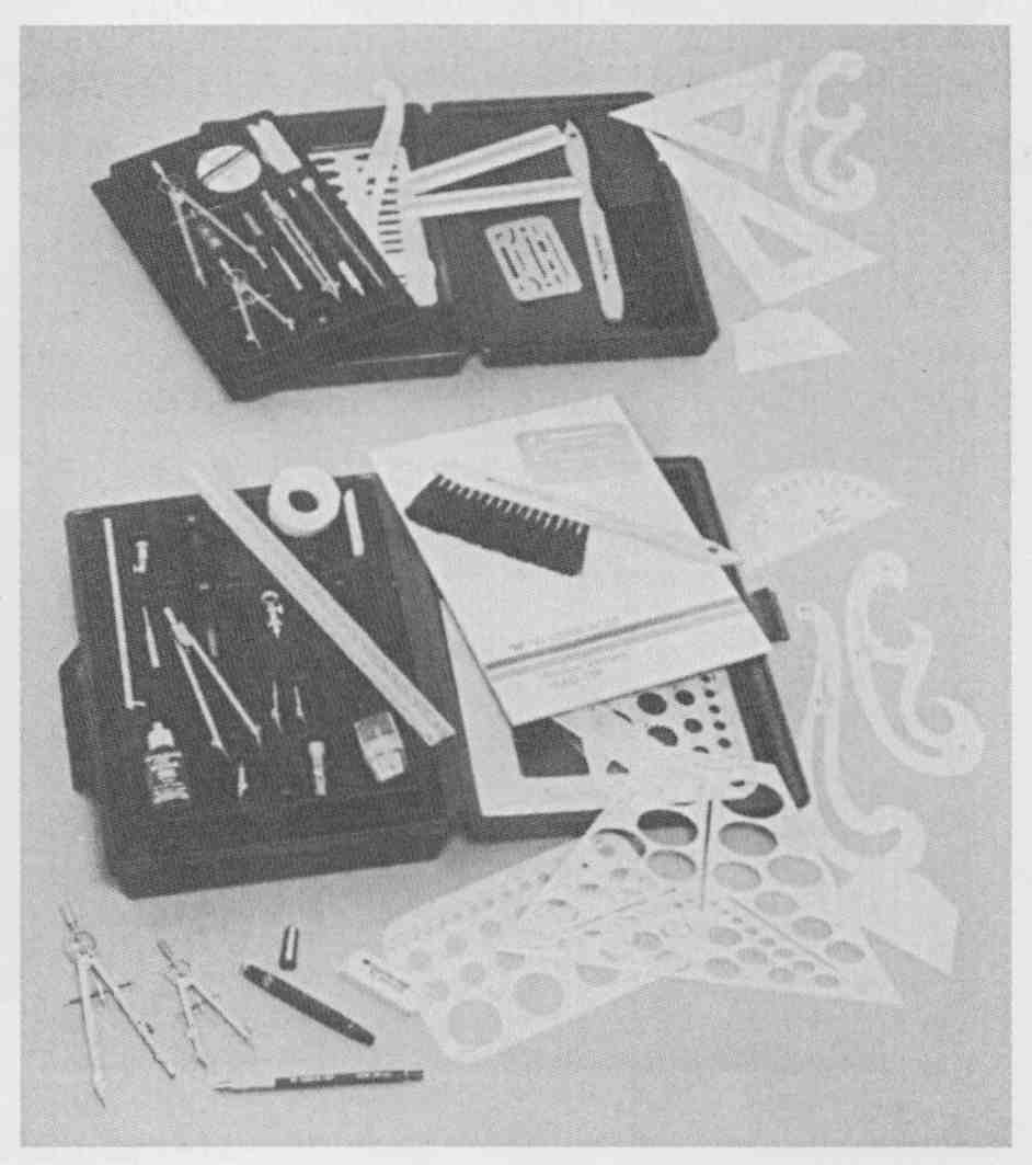
FIG. 17 Drafting tools. (Courtesy Teledyne Post)
Pencils
The choice of pencil, mechanical lead holder, or thin- line mechanical pencil depends on the preference of the user. All forms of drawing pencils can be used to do excellent linework and lettering. In many cases the choice of pencil is determined by cost. Traditional wooden pencils are the cheapest but are also the hardest to keep sharpened with a consistent conical point.
The lead holder, shown in Fig. 18, has replaced the wooden pencil. It holds a long single stick of lead.
FIG. 18 Drafting lead holders. (Courtesy Koh-I-Noor Rapidograph, Inc.)
= = =
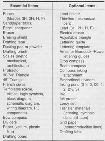
TABLE 1 Manual Drafting Tools
Essential Items:
- Pencils (Grades 3H, 2H, H, F)
- Sandpaper block
- Pencil sharpener
- Eraser
- Erasing shield
- Drafting tape
- Dusting pad or powder
- Drafting brush
- Scales (metric, mechanical, architectural)
- Protractor
- 30/60 degree Triangle
- 45° Triangle
- French curve
- Templates (circle, ellipse, logic symbols, block diagram, schematic diagram, wiring diagram, PC component)
- Bow compass
- Dividers
- Paper (vellum, plastic film)
- Drafting board
- Optional Items:
- Lead holder
- Thin-line mechanical pencil
- Lead (3H, 2H, H, F)
- Electric eraser
- Adjustable triangle
- Lettering guide
- Lettering template
- Ames or Braddock—Rowe lettering guides
- Drop compass
- Beam compass
- Compass inking attachment
- Proportional dividers
- Inking pens (3 x 0, 00, 1, 2, 2½, 3)
- Ink
- Ink eraser
- Leroy set
- Transfer materials (lettering, symbols, dolls, slit tape)
- Grid paper (non-reproducible lines)
- Drafting table
= = =
Having more than one lead holder ready with various leads ensures that a variety of lead grades is quickly available. This drawing tool is easily sharpened and increases the speed, consistency, and ease of drafting.
The thin-line mechanical pencil is an excellent tool for drawing consistent-width lines and letters. It never requires sharpening. As shown in FIG. 19, thin-line mechanical pencils come in metric sizes, including .3, .5, .7, and .9mm. These sizes are used to draw the typical lineweights: .35 to .45 mm (centerlines, dimension lines, construction lines), .5 to .7 mm (object lines, diagram flow lines, hidden lines), and .7 to .9 mm (cutting plane lines, borders, emphasized diagram flow lines). The trouble with thin-line pencils is the simple fact that each pencil holds only one thickness of lead. The purchase of multiple thin-line pencils (or mechanical lead holders) may be prohibitively expensive. Of course, when using a smaller pencil, you can thicken the line to any width desired. The thinner the lead, however, the more frequently it breaks. Another drawback to thin-line mechanical pencils is that they are difficult to work with when using a lettering guide or a template.

FIG. 19 Ultra-thin mechanical pencil. (Courtesy Berol RapiDesign)
To gain experience with the three types of drawing instruments, purchase two types of wooden pencils (H and F), one lead holder with three or four lead grades (F, H, 2H), and a .5- or .7-mm thin-line mechanical pencil with a range of lead grades. The thin-line pencil should be used for lettering and the lead holder, for most darkened linework. The wooden pencils can be used for lettering and all types of lines.
Regardless of the type of drawing pencil that you choose, purchase a variety of leads. Standard graphite leads used on vellum and film drafting mediums range from soft and dark (6B, 5B, 4B. 2B, B, HB, and F) to the medium hard and dark (H, 2H, 3H). The hardest and lightest types are 4H, 5H, 6H, 7H, 8H, and 9H. In general, only the medium leads are used: 2H and 3H for construction lines and blocking in a drawing, H for darkened finished lines. Some drafters prefer HB for finished lines, but great care must be taken to ensure that the drawing is kept clean and unsmudged. To be adequately reproduced, all lines must block light if a whiteprinter is used, or they must be dark and thick enough to be recorded by a camera if a photocopier or micrographics aperture card machine is used.
Plastic leads are used on plastic film drawing mediums, as shown in FIG. 20. Film leads come in a variety of grades (E, K, CF, and so on).
Lead holders and wooden pencils require frequent sharpening. FIG. 21 shows an electric sharpener. A sharp conical point is needed to make thin, erasable lines required for the construction stage of the project. For darkened, finished linework, slightly dull the pencil point on scrap paper to avoid frequent breaking. To maintain the line thickness, rotate the pencil or lead holder as the line is drawn. A sharpened but slightly dulled lead point is also required for lettering. The advantage of using a thin-line mechanical pencil lies in never needing to sharpen the lead, since it is a consistent thickness.
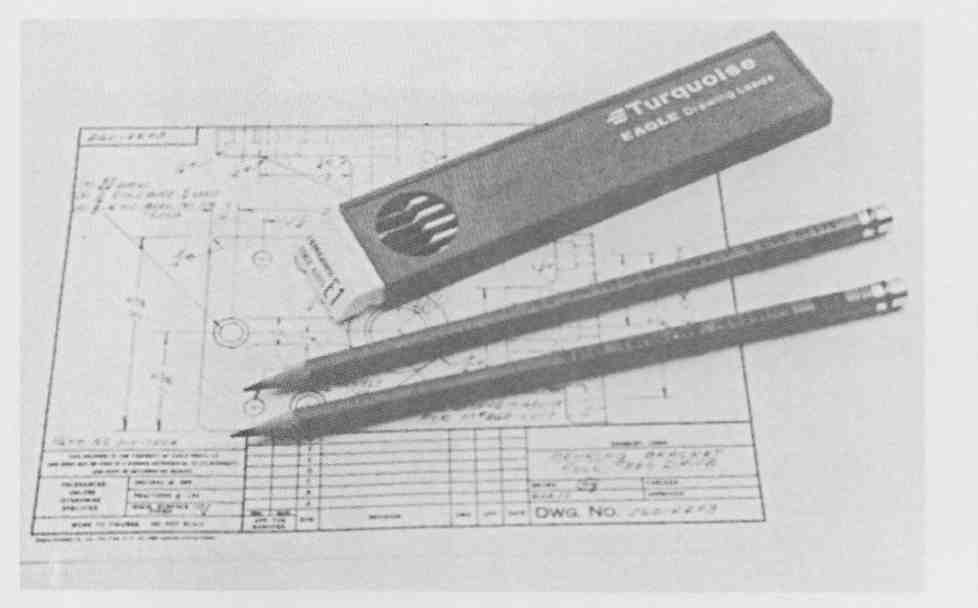
FIG. 20 Wooden pencils and plastic leads (grade E1) for drafting film.
(Courtesy Berol RapiDesign)
One sharpening device that is necessary for wooden pencils and lead holders is the sandpaper pad shown in FIG. 22. A sandpaper pad is used to sharpen lead points on compasses and pencils. Compass leads are sharpened as wedge shapes instead of conical points in order to slow down the dulling process. After sanding the lead, wipe it clean with a soft cloth or tissue.
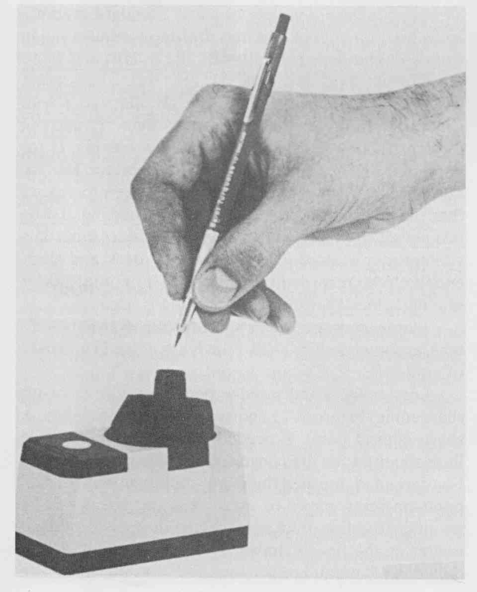
FIG. 21 Lead holder and pencil sharpener. (Courtesy Berol RapiDesign)
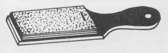
FIG. 22 Sandpaper pencil pointer. (Courtesy Hearlihy & Co.)
Erasing Tools
Erasers come in many shapes and sizes, from hand held, as shown in FIG. 23, to electric, shown in FIG. 24. Regardless of the expertise of the drafter, erasing is unavoidable. Manual and electric erasers come in many grades. Pink Pearl and Art Gum erasers are used for both paper (vellum) and drafting film. Special vinyl erasers ( FIG. 23) are available for erasing inked drawings on drafting film. Note that ink is extremely hard to erase when used on paper. An electric eraser is essential in this situation, but great care is required to avoid rubbing holes in the paper. An electric eraser should not be used on drafting film, since it tends to destroy the tooth, or surface, of the drafting film. For ink drawings completed on film, a small amount of moisture applied to a vinyl eraser is the best technique.
To save the linework around the erasing area, an erasing shield, shown in FIG. 25, is used. Erasing shields are thin metal plates perforated with different holes and slots that can be positioned over only the portion of the line to be removed.
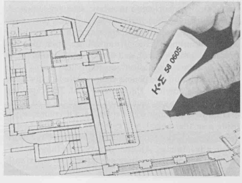
FIG. 23 Vinyl eraser for drafting film. (Courtesy Keuffel & Esser/Kratos)
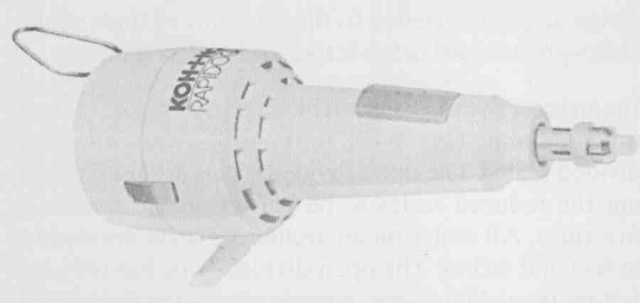
FIG. 24 Electric erasing system. (Courtesy Koh-i-Noor Rapidograph,
Inc.)
Two other items are essential for clean, unsmudged drawings: a dry cleaning pad (an erasing dust pad) and a drafting brush. Dry cleaning pads contain ground eraser pieces and powder. They are used to remove dirt and leftover crumbled graphite deposited from drawing and lettering. When you use a dry cleaning pad, don’t drag it across the drawing instead, lightly pat the linework and lettering after a small portion of the drawing is complete. Then use a drafting brush, shown in FIG. 26, to sweep the drawing clean of powder and dirt. Frequent patting and dusting ensure a higher-quality drawing, although you must be careful not to lighten the lines and lettering by too much dusting.
Scales
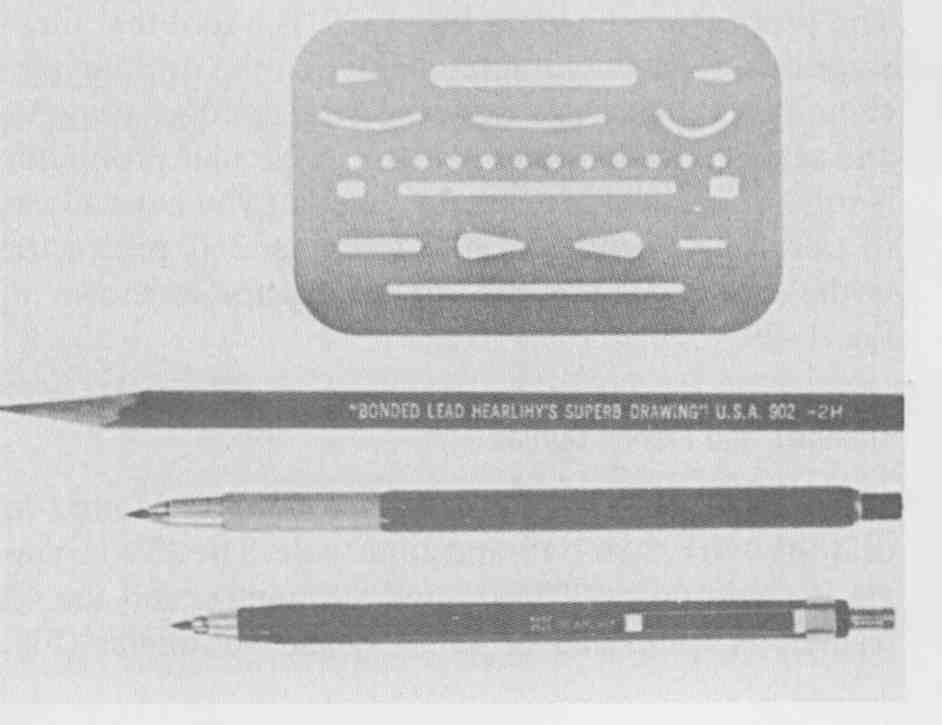
FIG. 25 Metal erasing shield, drafting pencil, and lead holder. (Courtesy
Hearlihy & Co.)
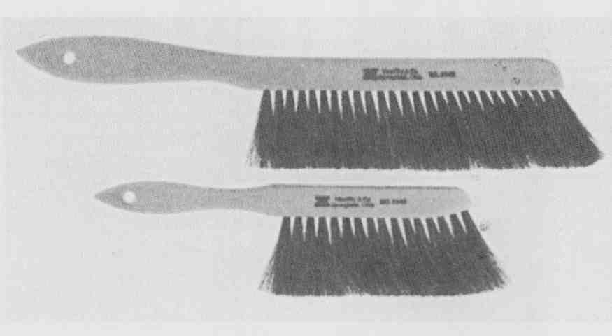
FIG. 26 Professional drafting brush and student drafting brush. (Courtesy
Hearlihy & Co.)
Instrument drawings show each aspect of an object or graphical form in proper proportion. The size of the drawing may be the full size of the shape or it may be reduced or enlarged. For electronic diagrams, the choice of drawing size is normally determined by the complexity of the diagram and the sheet size, since electronic drawings are normally without a particular scale. For sheet metal drawings (panels, enclosures, cabinets, chassis) on electronic equipment, the choice of scale depends on the size of the object, as in traditional mechanical drafting. A drawing with accurate proportions is said to be drawn to scale. Scales are measuring instruments that are made to accurately represent specific units of measurement. The scale is a precision instrument and, with proper use, will help you produce consistent drawings.
Four basic scales are available: mechanical engineer, civil engineer, architect, and metric. In electromechanical work the mechanical engineer’s scale and the metric scale are the most frequently used. The civil engineer’s scale, shown in FIG. 27, is used to draw very large projects. The architect’s scale, shown in FIG. 28 (top), is used to make drawings of buildings and structures, as well as to enlarge or reduce drawings in electromechanical work. A metric scale, shown in FIG. 28 (bottom), is used for all types of projects and is easily adaptable to every form of technical and engineering work.
The civil engineer, architect, and metric scales are triangular and are about 12 in. long. The triangular shape makes six surfaces available for the different- sized scales.
The markings on the scales are arranged in two ways, fully divided and open divided. A fully divided scale has each main unit completely divided into specific units, as in the metric, civil engineer’s, and mechanical engineer’s scales. An open-divided scale has each main unit of the scale undivided, and an extra main unit is fully divided at the 0 end of the scale. The architect’s scale is open divided.
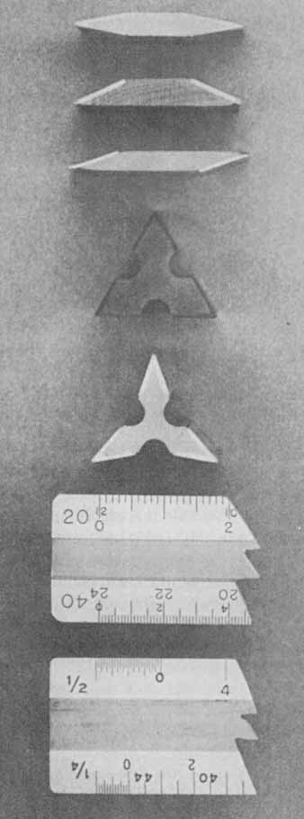
FIG. 27 Flat and triangular scales. (Courtesy Teledyne Post)
The Mechanical Engineer’s Scale. The mechanical engineer’s scale, which is two sided, is flat. One side is the full-inch scale, which is divided into either decimal units of .10 in. or as many as 50 divisions (every .2 in.). The opposite side is at half-scale (1: 2).
The Civil Engineer’s Scale. The civil engineer’s scale is either the two-sided type or the three- sided type, which has six scales that are equally divided. These scales have 10, 20, 30, 40, 50, and 60 divisions per inch and are numbered at each tenth division along the length of each scale. The number of divisions per inch is marked at the 0 end of each scale. The user can assign any units needed to the divisions of these scales, although the usual usage is that each division equals 1 ft.
The Architect’s Scale. The architect’s scale has afoot ruler full-sized scale ( FIG. 28, top) and ten reduced, open- divided scales. The open-divided scales are used to permit the reduced scales to be placed on the remaining five sides. All scales on an architect’s scale are divided in feet and inches. The open-divided scale has only full, 1-ft units reading in one direction from the 0 as well as a fully divided 1-ft unit reading in the opposite direction. Therefore, the number of feet is read along the length of the scale and the number of inches is read in the fully divided unit at the 0 end of that same scale, both numbers becoming larger as the distance from the 0 becomes greater. Each scale is identified by the number or fraction at the 0 end, which indicates the unit of length in inches that represents 1 ft of real size.
The Metric Scale. Metric units, also called SI units (Système Internationale d’ Unités), are measured with a metric scale. The full-sized metric scale ( FIG. 28, bottom) is divided into major units of centimeters and smaller units of millimeters. There are 10 millimeters in each centimeter. (See Appendix A for U.S. customary and metric equivalents.) Metric units in full scale as well as in reductions and enlargements are used in all forms of electronic work.
This text has been designed to be used with all types of scales. Many problems in the text are undimensioned, allowing your instructor to ch the unit of measurement. Use of different scales is suggested. Table 2 compares the four basic scales.
Protractor
The protractor, shown in FIG. 29, is a tool that measures angles instead of lines. Note that the drafting ma chine can replace not only the straightedge, triangle, and scale, but also the protractor. A circular protractor is still an excellent investment, whether you have access to a drafting machine or not. A circular 360° protractor is the easiest to use. A 180° protractor is shown in FIG. 29.
Triangles and French Curves
Three basic types of triangles are normally found in drafting work, 30/60,45, and adjustable. The 30/60 triangle is made up of 30°, 60°, and 90° angles, and the 45-degree triangle is composed of 45°, 45°, and 90° angles ( FIG. 17). The adjustable triangle, shown in FIG. 30, is very useful although more expensive. Adjustable triangles can be set at any angle between 00 and 90°. The higher cost of an adjustable triangle is partly overcome by the fact that it can take the place of both the 45 and 30/60 triangles. Triangles are used to draw all straight lines that are not horizontal when a T square or parallel bar is used.
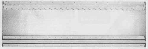
FIG. 28 Architect’s scale and metric scale. (Courtesy Teledyne Post)
For curved lines that are not circles or circular arcs, a French curve ( FIG. 29) is required. Triangles and French curves are made of a hard, flexible, clear plastic.
Templates
A template is a tool for drafting shapes of all sizes. Standard templates, shown in FIG. 31, are essential for the-quick, easy construction of circular, square, rectangular, triangular, and elliptical shapes. Electronic templates, shown in FIG. 32, are one of the most important pieces of equipment in electronic and electrical drafting and design. Seldom are any of the vast array of electronic symbols ever hand-constructed except in the sketching stage. After you master the essentials of linework and compasswork, use templates for all standard shape construction. Templates are presented throughout this text when electronic and drawing applications, pictorials. electronic diagram construction, and printed circuit board layout are discussed.
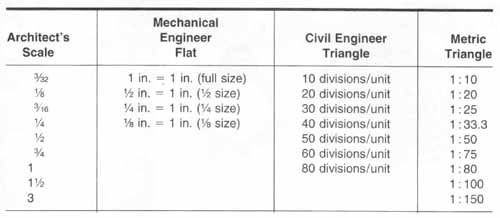
TABLE 2 Basic Drafting Scales
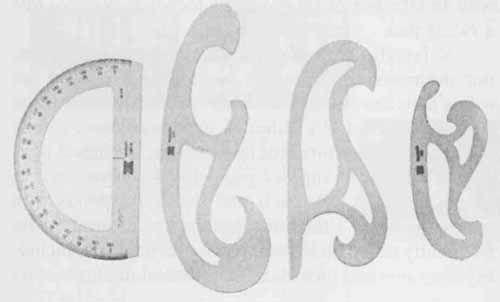
FIG. 29 Protractor and French curves.
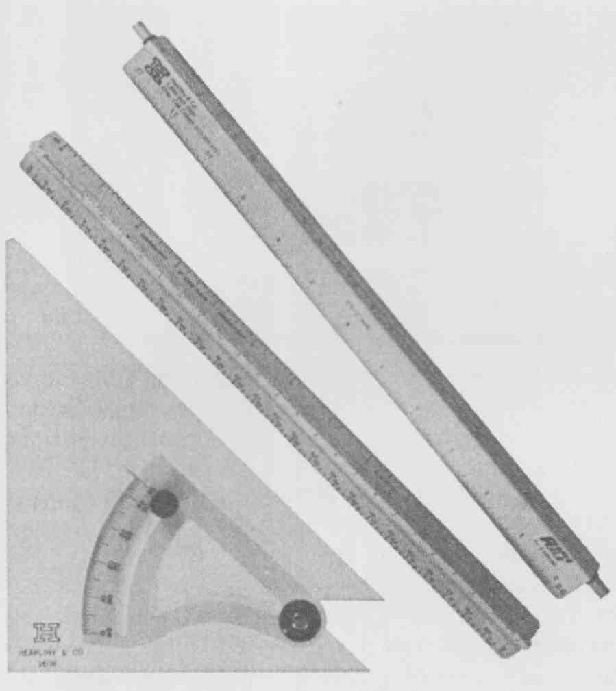
FIG. 30 Rapid rule, architect’s scale, and adjustable triangle.
INSTRUMENTS
Instruments include all forms of compasses and dividers. The drafting instrument set, shown in FIG. 33, is commonly composed of one or two sizes of compasses, a divider, and accessories. The compass is used to draw circles and circular arcs. Although a wide variety of drafting sets is available, they normally contain such useless and obsolete items as the ruling pen ( FIG. 33). This item has been totally replaced by the technical pen. As a beginning drafter you need only purchase a medium-sized, high-quality bow compass and a divider.
Three expensive but extremely useful tools are available for special situations: the drop compass, shown in FIG. 34, for very small accurate circles: the beam compass, FIG. 35, for very large circles and arcs; and proportional dividers, FIG. 36, for reductions and enlargements. Most electronic drafters and designers need only a good set of dividers and a medium-sized bow compass.
Most compasses can have inking pen or technical pen attachments, as shown in FIG. 37. When purchasing a compass set, make sure that it can be equipped with an attachment for holding a technical pen, not just a ruling pen.
Although many drafting sets contain ruling pens, our discussion is limited to technical pens, since the ruling pens are not used in industry. Technical pens like the one in FIG. 38, although expensive, have totally replaced all other forms of inking tools. Technical pens come in a wide range of pen widths (diameters), as shown in FIG. 39. Each pen size corresponds to a metric thickness. Electronic drafters and illustrators are frequently called on to complete a project in ink, including diagrams and pictorials for technical manuals, sales brochures, and graph and chart presentations. In general, technical pens in .25-, .35-, .45-, .50-, and .70-mm sizes are required for such drafting. (See section 3 for ANSI line-width standards.)
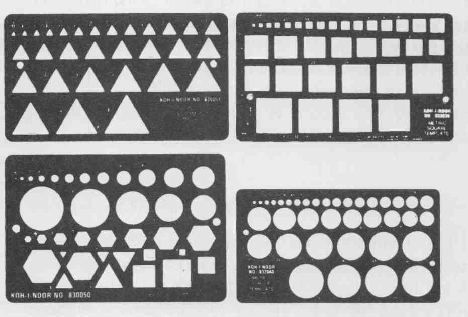
FIG. 31 Templates. (Koh-i-Noor Rapidograph, Inc.)
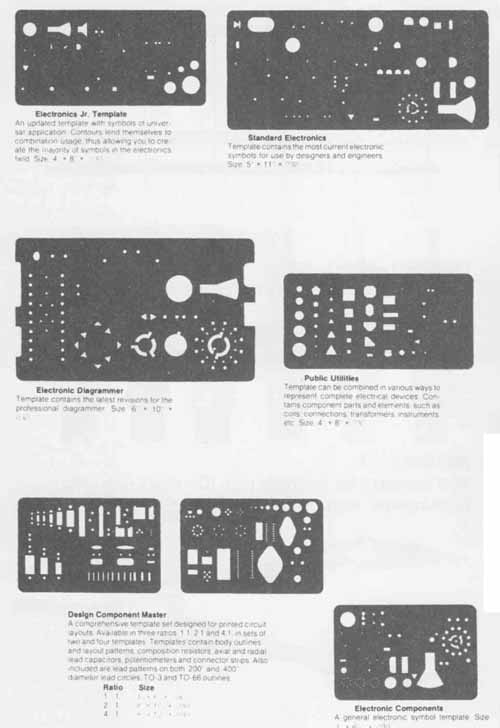
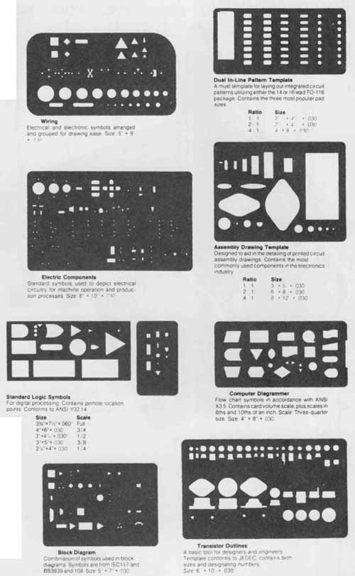
FIG. 32 Electronic and electrical templates. (Koh-i-Noor Rapidograph,
Inc.)
MATERIALS
Drafting materials include drawing papers (vellum, film, grid, preprinted) and preprinted transfer items (title blocks, lettering, electronic symbols, and printed circuit artwork aids).
An extensive variety of electronic drafting aids is available; in fact, electronic drafting has been at the forefront of all technological advances concerning pin graphics, appliqués, transfer symbols, and other time saving items.
This text does not discuss title block construction or borders, since industry typically uses preprinted vellum or film standard drafting paper sizes with company or standard title blocks and borders. Your instructor can assign title block format with specific problems.
The completion of the title block is one of the most important parts of a project. The title block normally includes spaces for the following information:
--Company or school name
--Project title or part name
--Scale
--Drawn by
--Material specification
--Date
--Checked by
--Sheet number
--Drawing number
--Revision
--Standard company tolerances
Preprinted company title blocks need only be filled in by the drafter or designer. Title blocks will need to be constructed according to school, company, or ANSI standards when preprinted blocks are not available. Since many instructors have their own title block for mats, this text leaves format selection to the instructor. Border widths also need to be specified. For general drawing practice. ½ in. (12.7 mm) can be used for size C sheets and larger. For small format paper, A and B sizes, ‘/4 in. (6.35 mm) can be used. Check with your instructor before using these border widths.
Title blocks and paper or film are covered by the ANSI standard Drawing Sheet Size and Format, ANSI Y14.1—1980. Your instructor can assign paper types, sizes, and format as necessary. An ANSI standard title block is shown in FIG. 40.
FIG. 33 Drawing instruments: ruling pen, compass, and dividers. (Courtesy VEMCO Corp.)
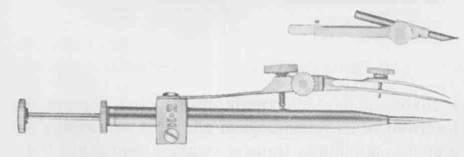
FIG. 34 Drop bow pen and lead compass. (Courtesy Keuffel & Esser/Kratos)
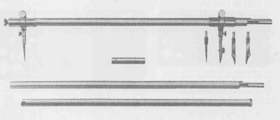
FIG. 35 Beam compass. (Courtesy Keuftel & Esser/Kratos)
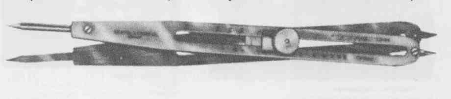
FIG. 36 Proportional dividers. (Courtesy Keuftel & Esser/Kratos)
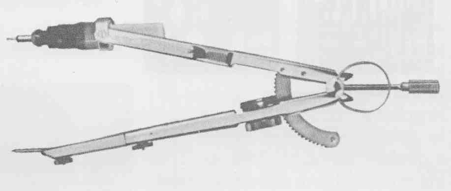
FIG. 37 Bow compass for technical pen. (Courtesy Koh-i-Noor Rapidograph,
Inc.)
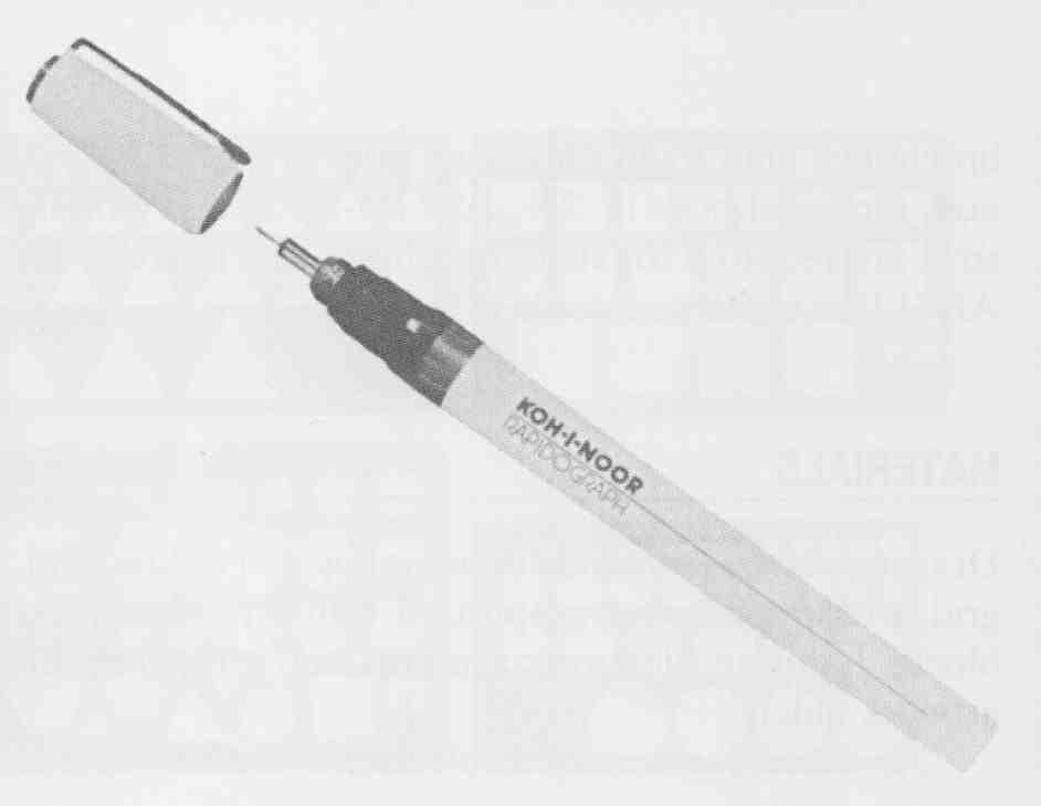
FIG. 38 Technical pen. (Courtesy Koh-i-Noor RaDidoaraoh. Inc.’
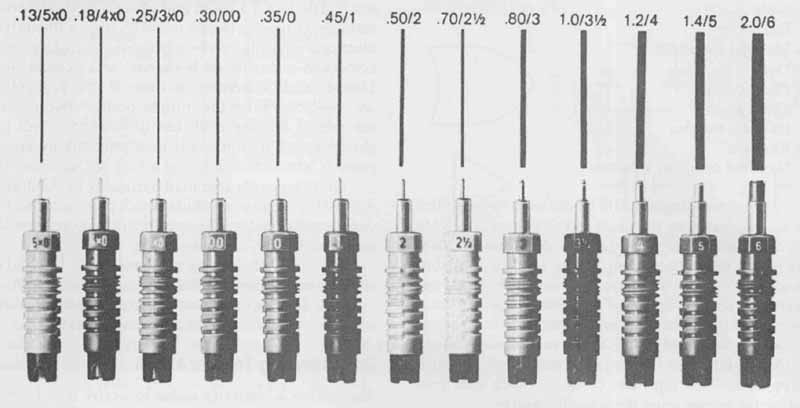
FIG. 39 Pen sizes and tip widths.
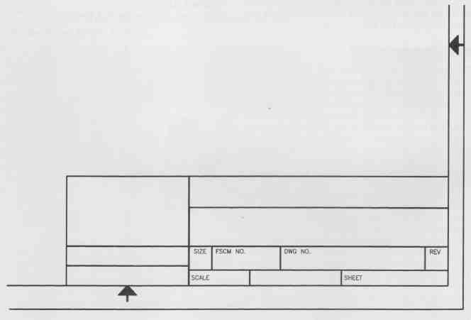
FIG. 40 ANSI standard title block.
Drafting Mediums
Traditional drafting mediums that are transparent enough to be whiteprinted include vellum, drafting cloth, and drafting film. Vellum and plastic film are the most widely used throughout industry.
All drafting mediums are secured to the drafting table with drafting tape. Drafting tape is a high quality version of masking tape, but is designed not to pull the finish off the paper surface. Note that many drafters have tried staples and tacks without success, since they tear the drawing medium and destroy the drafting table surface.
Drawing paper, sometimes referred to as vellum, is a high-quality translucent drawing paper. Vellum is an excellent drawing medium, since it is translucent enough to be reproduced in a whiteprinter. Vellum is easily erased when pencil is used, and it takes ink well.
Drafting film is made of durable, high-quality poly ester sheets. This drafting medium is excellent for ink and plastic lead alike. Special drafting-film-grade leads and erasers are also available. Although it is expensive compared to vellum, every student should have some practice drawing on drafting film, with both plastic lead and ink.
Both drawing paper (vellum) and drafting film are available plain and with a fine non-reproducible or fade out grid pattern. Fade-out grid paper is used extensively throughout the electronics industry, since a majority of electronic drawing involves two-dimensional diagrams composed primarily of horizontal and vertical lines. United States customary and metric unit grid rulings are available. Since the introduction of drafting film, the use of drafting cloth has diminished. Cloth is a closely woven muslin and is used primarily for special projects where durability and a long life are essential.
Other types of paper used frequently by the drafter, designer, or engineer include sketch pads, cross-section paper, and special graph paper, such as log—log, semilog, linear, and polar, as shown in FIG. 41.
All forms of drafting mediums come in standard sheet sizes, as shown in Table 3, and rolls.
Roll drafting paper and film are available in widths of 30, 36, 42, and 54 in. in 25-ft lengths and up.
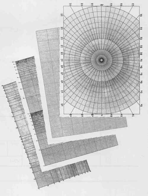
FIG. 41 Graph paper. (Courtesy Keuffel & Esser/Kratos)
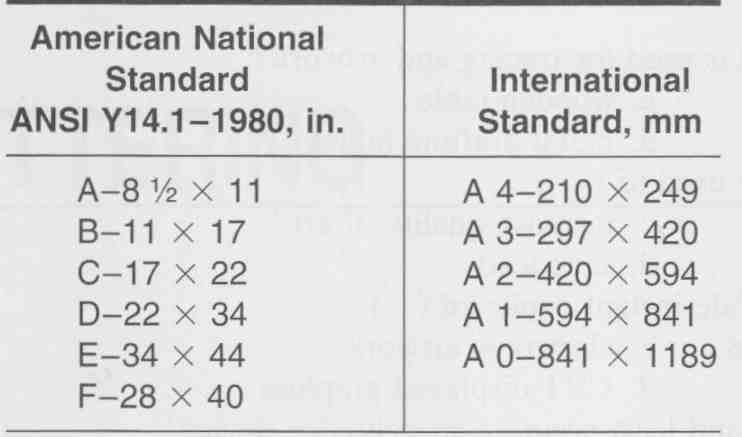
TABLE 3: Standard Paper Sizes
Printed Drafting Transfer Aids
The electronics industry makes extensive use of rub-on and transfer preprinted letters, numbers, symbols, lines, and standard shapes. Printed drafting aids are available in many shapes and sizes, as shown in FIG. 42. Electronic and electrical symbols, conductor strips. component shapes, and slit tape have replaced hand-drawn lines and symbols in many instances, especially for printed circuit board artwork, as shown in FIG. 43.
FIG. 42 Precut StickOn transfer symbols. (Bishop Graphics, Inc.)
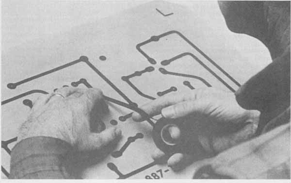
FIG. 43 Tapes for printed circuit board artwork, where consistent precision
line widths are required. (Courtesy Graphic Products)
REVIEW QUESTIONS
Many of the technical terms discussed in this and other sections may be unfamiliar to you. Consult glossaries for definitions of terms when necessary.
1. Which type of drafting board is used for tracing and artwork?
a. digitizer c. wooden table
b. light table d. metal drafting table
2. Dry-transfer drafting aids are used to ( ).
a. replace drafting c. increase quality of art
b. increase speed d. save lead
3. CAD hard-copy devices provide instant copies of ( ).
a. permanent design drawings c. electronic artwork
b. drafting layouts d. CRT-displayed graphics
4. Which item is the least used and least accurate straightedge device?
a. parallel bar c. T square
b. CAD digitizer d. drafting machine
5. Light pens, wooden pencils. mechanical lead holders, and ( ) are used to draw or draft.
a. electronic pens c. thin lines
b. cursors d. compasses
6. A sandpaper pad is used to ( ).
a. file c. sand
b. shave - d. sharpen
7. Dry cleaning pads are used to ( and ) a drawing.
a. dust c. clean
b. remove graphite d. rub
8. An architect’s scale is ( ) divided.
a. partially c. fully
b. open d. half
9. An adjustable triangle cannot be used as a ( ).
a. 30/60 triangle c. foot scale
b. protractor d. 45 triangle
10. Which two instruments are obsolete?
a. ruling pen c. divider
b. cursor d. T square
11. Define the following terms:
- CAD
- micrographics
- vellum
- lead holder
- thin-line mechanical pencil
- plotter
- printer
- template
- light table
- grid paper
- CRT
- floppy disk
- magnetic tape
- microfilm
- digitizer
- drafting machine
- drafting table
- scale
- architect’s scale
- sandpaper pad
- dry cleaning pad
- erasing shield
- bow compass
- beam compass
- metric scale
- light pen
- drafting film
- drafting brush
- drafting tape
- adjustable triangle
- dividers
- drop compass
- technical pen