AMAZON multi-meters discounts AMAZON oscilloscope discounts
INTRODUCTION
High-quality drafting skills associated with all forms of engineering are essential when graphics are used to communicate design, production, and manufacturing data. An engineer, designer, or drafter’s graphical calculations must be neat and accurate to convey the proper message. In many cases the drawing will be reproduced by such processes as whiteprinting, photocopying, or reducing onto microfilm. Lettering and linework must be dark and of high quality. This section, an overview of the basics of linework, provides guidelines, procedures, and techniques for developing high-quality drawing skills.
Drafting pencils are graded according to the hardness of their lead, which determines the quality and shade of the line that can be drawn. A hard lead can make a very sharp, accurate, and thin line, which is quite beneficial for design calculations that need not be reproduced. Hard leads do not reproduce well in most cases. A soft lead will make dark lines, but their leads are very difficult to keep sharp. There are 11 grades of lead, from hardest to softest: 9H, 8H, 7H, 6H, 5H, 4H, 3H, 2H, H, F, and HB. For electronic drawings on a good grade of drafting paper, 3H or 4H is recommended for layout and construction of linework; H or 2H is
suggested for reproducible lines and for lettering. These leads, when used properly, produce excellent drawings having sharp, dense lines and dark, readable letters that will make good prints. A hard lead like 3H or 4H is sufficient for sketches used to lay out electronic diagrams and other electronic drawings before they are digitized on a CAD system. A digitizer is used with a menu (with electronic symbols and lines) to construct the diagram on the CRT. FIG. shows a CAD operator digitizing an electronic symbol. In FIG. 2, each of the four CRTs has a different type of electronic drawing displayed.
LINE WORK AND TECHNIQUE
Knowledge of lines and their symbolic meanings is essential to the electronic drafter. The most important aspect of an electronic drafter’s job is the understanding of the process, intent, and content of an electronic drawing. In electronics, most drawings are made up of single line diagrams, primarily composed of straight vertical and horizontal lines. Related drawings used for manufacturing electronic equipment include multiview, dimensioned drawings: equipment drawings, sheet metal enclosure layouts and developments, and component drawings. Graphs and charts are frequently used to rep resent tabular and related data.
Most electronic drawings are used to describe a process. The single-line diagram is the most frequently used to convey this information. Therefore, unlike mechanical drawings, where the shape description and projection technique are most important, electronic drawings require mastery of the symbol meaning, as well as of the actual symbols and lines used.
Although the types of drawings, linework, and weights are varied in the field of electronics, the most common drawing is the single-line diagram. Block diagrams, shown in FIG. 3, logic diagrams, FIG. 4, schematic diagrams, FIG. 5, and wiring diagrams, FIG. 6, are all single-line diagrams.
All drawings are made of lines that convey an idea from the drafter to the user. The control the drafter has over the pencil or pen and the techniques determine the quality of the drawings produced. The serious drafter, designer, or engineer constantly strives to improve technique through practice and attention to detail.
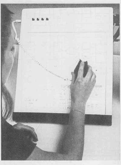
FIG. 1 Line Technique Electronic diagram menu. (Courtesy Bausch & Lomb
interactive Graphics Division)
A properly drawn line is uniform for its entire length.
You can make a line consistent in two ways:
1. Incline the pencil or lead holder so that it makes an angle of about 60-degree with the surface of the paper and then pull in the direction that it is leaning.
2. Rotate the pencil or lead holder slowly as the line is drawn and maintain a semi-sharp point. This will enable you to control the thickness and quality of the line.
These techniques take practice but will soon be come automatic, and lines will be uniform from end to end and from one line to another. Most diagrams are drawn with one lineweight both for the symbols and for the vertical and horizontal lines representing the flow of the system. FIG. 7 is a wiring diagram with three lineweights. Different lineweights can be used to emphasize a particular portion of the circuit, as illustrated in FIG. 8.
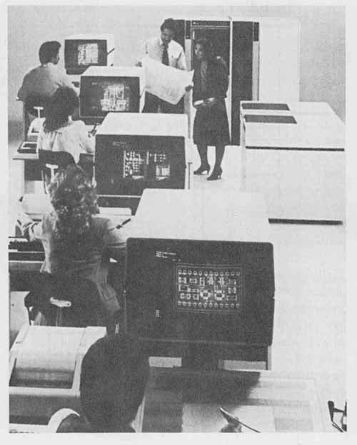
FIG. 2 Four types of electronic diagrams displayed on CRTs. (Courtesy Prime-Computervision
Corp.)
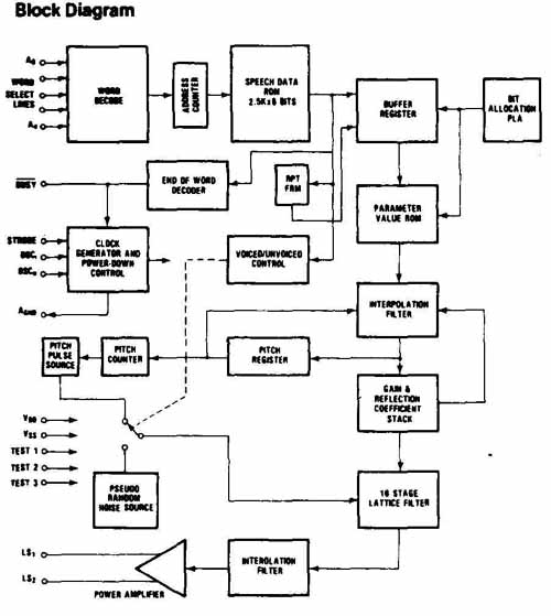
FIG. 3 Block diagram. (Courtesy American Microsystems, Inc.)
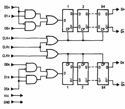
FIG. 4 Logic diagram. (Courtesy TRW LSI Products)
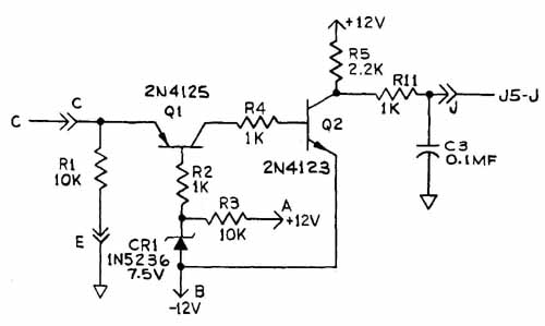
FIG. 5 Hand-drawn schematic diagram.
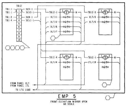
FIG. 6 Portion of a control panel layout and interconnection wiring diagram.
(Courtesy California Computer Products, Inc.)
Since most drawings are reduced or enlarged at times, correct lineweights and line techniques are essential. For drawings that are to be enlarged, special care must be taken since even the smallest mistake tends to mushroom. In other words, the mistake will also be enlarged. For drawings that are to be reduced — for in stance, printed circuit artwork drawings that are normally drawn at 2:1 or 4:1 enlargements — the corresponding reduction will clean up and reduce any small problems. It is important to draw the project accurately, however, at whatever scale is used and not to rely on a subsequent reduction to hide any poorly constructed areas of the drawing.
For CAD-generated drawings the lineweights are drawn and altered to any desired thickness, depending on the project, company standard, or special requirements for the drawing. CAD systems allow flexibility in the construction and revision of lines and symbols, as shown in FIG. 9. Lineweights can be exactly reproduced every time the drawing is plotted.
How well lines will print is determined by their density—that is, by how dark they are. Density is con trolled by the hardness of the lead and by the pressure applied while the line is drawn. The width and sharpness of the line are determined by the size of the point touching the paper. A pencil point must always be smoothed and rounded on scratch paper after being re-pointed. It can also be re-sharpened on scratch paper. Uniform lines require uniform point preparation.
Thin-line pencils are widely used. These excellent lead holders are available in different lead thicknesses. A .5- and a .7-mm lead holder with H or 2H leads work well for lettering and linework. Construction lines can be prepared with .3- and .4-mm fine-line pencils with 3H or 4H leads. These instruments require no sharpening and help maintain a high-quality, consistently uniform line. However, a different pencil must be purchased for each line thickness required, and the thinner leads tend to break more often when soft grades of lead are used. Holding a thin-line pencil almost vertically will reduce lead breakage.
Using a dust pad or erasing powder helps keep linework and paper clean. Brushing the paper frequently and using an extra piece of paper to rest the hand on while drawing will also help reduce smudges.
FIG. 7 CAD-drawn wiring diagram.
FIG. 8 Schematic diagram showing dashed, emphasized, and regular solid lines.
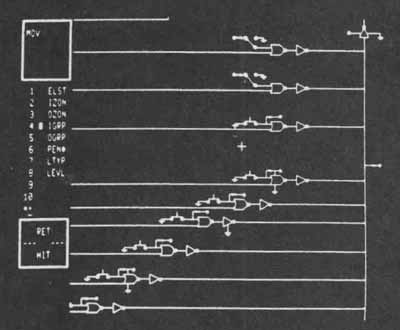
FIG. 9 Logic diagram displayed on a CRT.
Instrument Drawings
All drafters of electronic drawings use triangles and some form of straightedge (T square. drafting machine, parallel straightedge). As in mechanical drafting, electronic drawings are created as instrument drawings and are not to be constructed with anything except high-quality drafting instruments. Vertical lines are to be constructed with a straightedge and triangle. Horizontal lines are to be constructed with a straightedge that will give consistent parallel lines. Curved lines are to be plotted and then drawn with a compass, template, or French or irregular curve. No lines are to be formed without instruments. Only lettering can be formed freehand.
The drawing of an instrument line is a two-step process. First, determine the position and length of the line using dividers or a scale, and then draw the line with correct width and density. This process requires that you draw two completely different lines. The first line is for positioning and is thin and gray, drawn with 3H or 4H lead. This is called a construction line. It is suggested that you complete each electronic drawing problem totally using construction lines and then go over all lines to make them the proper thickness and density. This procedure ensures that all dimensions and measurements are taken from thin, sharp, accurate points and lines, creating a more precise and correct drawing. Draw the second line uniform, thicker, and more dense using H or 2H lead. Erase the lines used for construction purposes before you darken the drawing, unless company or school practice allows construction lines to remain on the finished drawing. Ask your instructor which method should be followed before completing your project.

FIG. 10 Electric eraser. (Keuffel & Esser/Kratos)
Erasing and Keeping the Drawing Clean
Erasing is a necessary part of drafting and, when done properly, improvements to drawings are easily made. The eraser should have good pickup power without smudging, such as a Faber Castell Pink Pearl. To protect adjacent areas that are to remain, all erasing is done through the perforations of a stainless steel erasing shield. Firmly hold the erasing shield in place on the drawing with one hand while erasing through a particular slot or hole with the other. Be sure not to erase surrounding areas through adjacent openings. After each erasing. brush the drawing so that erasing particles will not be ground into the drawing. Electric erasers like the one in FIG. 10 are also available.
All drawings attract dirt. Cleanliness does not just happen; it must be consistently cultivated. The following procedures help to keep drawings clean:
1. Clean hands: Periodically wash your hands to remove accumulations of graphite, dirt, perspiration, and body oils.
2. Equipment: Periodically clean with soap and water all tools that come in contact with the drawing. Clean tools that contain wood with a damp sponge. Scrub down drawing boards when they become soiled.
3. Graphite: Most dirt on a drawing is actually graphite dust (lead particles) resulting from drawing and from the lines themselves. Use the brush to remove this graphite dust before other tools smear it. This will help tremendously to keep drawings clean.
4. Pencil pointer: The pencil pointer leaves dust clinging to the lead after sharpening. After sharpening the lead, wipe it with tissue or poke it into a dry cleaning pad or a piece of scrap Styrofoam to remove clinging lead dust. Do not use the same dry cleaning pad to clean the drawing!
5. Equipment use: Proper use of the straightedge and triangles will always place these instruments between the hands and the paper, except for lettering. While lettering, always rest the hands on a clean sheet of scratch paper. Even clean hands put body oils onto the paper, and this oil has a magnetic effect on dirt.
Ink Drawings
Electronic drawings are frequently inked on drafting film or vellum. Electronic drawings used in sales literature, technical manuals, and pictorial illustrations are normally drawn in ink, since they need to be of photo graphic quality.
Ink drawings must be laid out in pencil and then traced or inked over the pencil lines. It is impossible to ink a drawing as it is laid out. Light tables are excellent for inking and tracing drawings. Triangles and templates must be raised from the drawing when ink is used be cause ink will tend to flow between the two surfaces and cause smeared lines. Specially designed equipment with a ledge or with inking risers prevents the equipment from being flush with the paper or film.
Ink drawings ( FIG. 10) should be prepared with technical pens, not ruling pens. Keeping the technical pen almost vertical helps prevent uneven and ragged linework. If possible, avoid having to take more than one pass for thin and medium lines. Extremely thick lines can be drawn with an appropriate pen size, al though better results may be attained if a thinner pen is used to thicken the line in stages.
Allow all ink to dry completely before moving to another portion of the drawing. Some drafters prefer to ink all horizontal lines from the top of the project downward and then from left to right. Erase ink lines very carefully, especially when drawing on vellum or another type of paper. You can easily erase ink from drafting film using the proper type of eraser and applying a small amount of moisture. As in pencil drawings, protect the surrounding lines while erasing.
Line Types
Printable lines for engineering drawings are drawn with different widths to provide specific information. In reality, each line type is a symbol and expresses an idea or communicates a special situation. It is important to understand that the thickness of any line is determined by its intended use and the smallest size to which it will be reduced. Lines representing the same type must be a consistent thickness throughout a single drawing to avoid confusion. The minimum spacing between parallel lines is determined by how much the drawing will be reduced. Two parallel lines that are placed too close together will merge if reduced; this process is called fill-in and must be avoided. Normally, .06-in. (1.5-mm) parallel spacing meets reduction requirements for most drawings.
The following list describes the thickness of lines on drawings.
1. Fine lines: Thin black lines used to provide information about the drawing or to construct the drawing. These include dimension lines, construction elements (permanent construction lines such as development elements), leader lines, extension lines, and center lines.
2. Medium lines: Intermediate, black lines used to out line planes, lines, and solid shapes (components and so on). Medium lines are also used for hidden and dashed lines and for symbols and flow lines on electronic diagrams.
3. Heavy lines: Solid, thick black lines used for the border, cutting plane lines, and break lines. Emphasized diagram lines are also heavy lines.
The one thing that all lines have in common is that they are black, clean-cut, precise, and opaque, with sufficient contrast in thickness between different types of lines.
Precedence of Lines
Whenever lines of different kinds coincide in a view, certain ones take precedence. Since the visible features of a part (object lines) are represented by thick solid lines, they take precedence over all other lines. If a centerline and cutting plane coincide, the more important one should take precedence, normally the cutting plane line, since it is drawn with a thicker lineweight. The following list gives the preferred precedence of lines on mechanical and non-diagramic electronic drawings:
- -- Visible or object lines
- -- Hidden lines
- -- Cutting planes
- -- Centerlines
- -- Break lines
- -- Dimension and extension lines
- -- Section lines
Line Conventions
This section provides a general overview of the accepted standard line conventions for mechanical drawings. The suggested standard line thicknesses are shown on the line key in FIG. 11. Examples are provided in FIG. 12. These lines are divided by thickness and format. Line types and conventions are covered in ANSI Standard Y14.2M for mechanical drawings. Electronic drafting includes many of these lines for production, assembly, manufacturing, and pictorial representation of electronic equipment. Suggested lineweights for specific electronic drawings and diagrams are discussed later.
Visible or Object Lines
Visible lines or object lines are thick lines used to represent the visible edges and contours of an object so that the views stand out clearly. This type of line is used to draw object outlines on mechanical drawings, component outlines for electronic drawings, and object out lines on sheet metal details. Visible lines must stand out from all other secondary lines on the drawing since they are the most important. In mechanical drawing, visible lines are normally drawn about .032 in. thick (between .5 and .7 mm).
Hidden Lines
Hidden tines consist of short, thin dashes, approximately .12 in. (3.0 mm) long, spaced about .03 to .06 in. apart to show the hidden features of an object. Hidden lines should always begin and end with a dash, except when a dash would form a continuation of a visible line.
Dashes always meet at corners, and an arc should start with dashes at the tangent points. When an arc is small, the length of the dash may be modified to maintain a uniform and neat appearance. Show only lines or features that add to the clearness and conciseness of the drawing. Eliminate confusing and conflicting hidden lines. Excessive hidden lines are difficult to follow. Where hidden lines do not adequately define an object’s configuration, a section should be taken. Whenever possible, hidden lines are normally eliminated from the sectioned portion of a drawing. Hidden lines should be drawn approximately .016 in. (.35 to .45 mm) thick.
Centerlines
Centerlines are composed of thin, long and short dashes, alternately and evenly spaced, with the long dash at each end. The long dash normally varies in length from .75 to 2 in. (19.0 to 50.8 mm), depending on the size of the drawing. Short dashes should be approximately .06 to .12 in. (1.52 to 3.0 mm), depending on the length of the required centerline. Very short centerlines may be unbroken, with dashes at either end.
Centerlines are used to indicate the axes of symmetrical parts or features, bolt circles, paths of motion, and pitch circles. They should extend about .12 in. beyond the outline of symmetry unless they are used as extension lines for dimensioning. Every circle should have two centerlines that intersect at its center on the short dashes. Extended centerlines are frequently used as extension lines. Centerlines are usually drawn about .012 in. (between .25 and .35 mm) thick.
Dimension Lines
Dimension lines are thin lines used to show the extent and direction of dimensions. Space for a single line of numerals is provided by a break in the dimension line. However, when two lines of numerals are used in the form of limits, one may be placed above and the other below an unbroken dimension line, when this is an acceptable company practice.
Dimension lines should be aligned if possible and grouped for uniform appearance and ease of reading.
Parallel dimension lines should be spaced not less than .25 in. (6.35 mm) apart. No dimension line should be closer than .38 in. (9.65 mm) to the outline of a view; .50 in. (12.7 mm) is the preferred distance.
When you draw several parallel dimension lines, stagger the numerals to make them easier to read. When possible, avoid crossing dimension lines and extension lines. Place the shorter dimension lines closer to the view, inside the longer ones, to avoid crossing extension lines. Do not use a centerline, an extension line, or an object line as a dimension line.
All dimension lines terminate with an arrowhead, a slash, or a dot. The preferred ending is the arrowhead. Arrowheads should be drawn with a ratio of 3: 1, length to thickness. Arrowheads are normally .0625 in. wide and .1875 in. long (1.58 X 4.76 mm). The size used, however, is determined by the drawing scale, the total drawing size and area used, and the reduction requirements. Large, elaborate arrowheads should be avoided. Dimension lines are drawn the same thickness as center lines, about .012 in. (between .25 and .35 mm).
Extension Lines
Extension lines are used to indicate the termination of a dimension. An extension line should not touch the feature from which it extends but should start approximately .04 to .06 in. (1.52 mm) away and terminate approximately .12 in. (3.0 mm) beyond the dimension line. Where extension lines cross other extension lines, dimension lines, leader lines, or object lines, they usually are not broken unless this is a company’s accepted practice. Where extension lines cross dimension lines close to an arrowhead, a break in the extension line at the arrowhead is recommended for clarity. Extension lines are drawn the same thickness as dimension lines and centerlines.
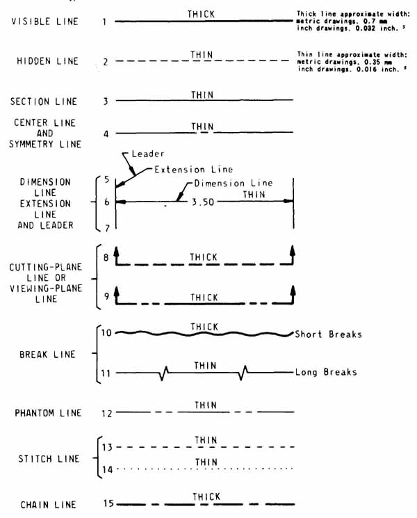
FIG. 11 ANSI Y14.2M, Width and Type of Lines. 5 The metric line widths agree
with ISO/DIS/128 (June 1917) and are not a soft metric conversion of the inch
value. These approximate line widths are intended to differentiate between
THICK and THIN lines and are not values for control of acceptance or rejection
of the drawings.
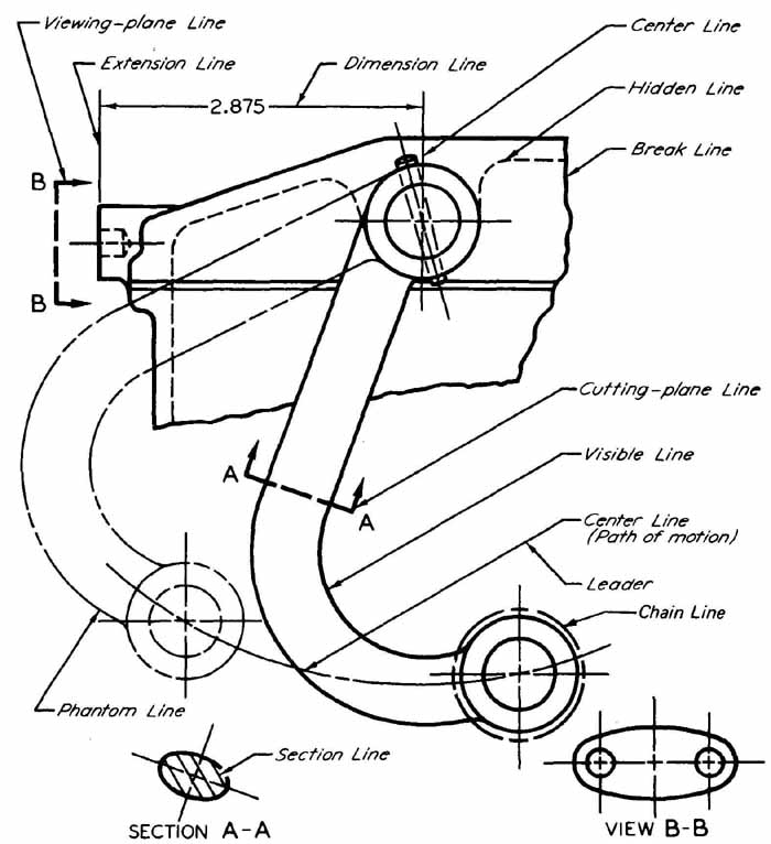
FIG. 12 ANSI Y14.2M, Application of Lines.
Leader Lines
A leader is a continuous straight line that extends at an angle from a note, dimension, or other reference to a feature where attention is directed. An arrowhead at one end. touches the feature. A horizontal bar .25 in. (6.35 mm) long at the note end terminates approximately .12 in. (3.0 mm) away from the mid-height of the lettering, either at the beginning of the first line or at the end of the last line, never from a point in between. Leaders should not be bent to underline the lettering or part numbers. Unless it’s unavoidable, they should not be bent in any way except to form the horizontal bar at the lettering.
Leaders usually do not cross. Leaders or extension lines may cross an outline of an object or other extension lines if necessary, but the lines usually are continuous and unbroken at the point of intersection. Where a leader is directed to a circle or circular arc, its direction should be radial. Leader lines are drawn the same thickness as centerlines, dimension lines, and extension lines.
Cross-Section Lines
Cross-section lines are uniformly spaced thin lines used to indicate the exposed cut surfaces of a part in a sectional view. Spacing should be between .06 in. (1.5 mm) and .12 in. (3.0 mm) depending on the possible reduction of the drawing. Cross-section lines are drawn slightly thinner than centerlines and dimension lines.
Phantom Lines
Phantom lines are made up of thin long and short dashes. They are used to indicate alternative positions of moving parts, adjacent positions of related parts, and repeated details. They also show the cast or rough shape of a part before machining. The line starts and ends with the long dash .60 in. (15.2 mm) or longer, and the short dashes are approximately .12 in. (3.0 mm) long, with about .06 in. (1.52 mm) space between. A phantom line is drawn approximately as thick as a hidden line.
Culling-Plane and Viewing-Plane Lines
Cutting-plane and viewing-plane lines are made up of thick, long dashes separated by two short dashes. They are used to indicate the location of cutting planes for sectional views and the viewing positions for removed views. These lines start and stop with long dashes .60 in. (15.24 mm) or longer, and the short dashes are approximately .12 in. (3.0 mm) long, with about .06 in. (1.5 mm) space between. An alternative method uses dashed lines for the total cutting plane. Both methods are acceptable. Cutting-plane lines are normally drawn with a thickness of about .032 in. (.70 mm).
Break Lines
Short break lines are thick, freehand, continuous lines that are used to limit a broken view, partial view, or broken section. For long breaks where space is limited, a neat break may be made with long, thin, ruled dashes joined by freehand zigzags. Break lines are drawn as thick as cutting-plane lines when the ragged method is used and about as thick as hidden lines when the long- break method is used.
Electronic and Electrical Line Conventions
Specific lineweights (thicknesses of lines) are not standardized for electronic drawings. ANSI Standard Y32.2, Graphic Symbols for Electrical and Electronic Diagrams, allows the drafter to decide the lineweights:
A4.3 Line Width. The width of a line does not affect the meaning of the symbol. In specific cases, a wider (heavier) line may be used for emphasis.
Although this standard refers to symbols, it can also be applied to the lines connecting the symbols, since they are normally drawn with the same thickness. Note that electronic and electrical drawings do not define the thickness of lines as meaning anything in particular, as do mechanical line conventions.
All electrical and electronic lineweights should con form with ANSI Y14.2. In 15—3.5, Line Conventions and Lettering of ANSI Standard USAS Y14.15—1966, Electrical and Electronic Diagrams makes the following recommendations:
The selection of line thickness as well as letter size should take into account size reduction or enlargement, when it is felt that legibility will be affected. A line of medium thickness is recommended for general use on diagrams. A thin line may be used for brackets, leader lines, etc. When emphasis of special features such as main or transmission paths is essential, a line thickness sufficient to provide the desired contrast may be used.
FIG. 13 illustrates recommended lineweights for electronic drawings and diagrams. The labels on this figure are explained in the following list:
A. Dimension Line, FIG. 13(1): Same as for mechanical conventions; used on dimensioned production drawings, pictorial drawings (1), component multiview drawings (6), and sheet metal details and layouts.
B. Object Line/Visible Line, FIG. 13 (6): Same as for mechanical drawings; found on the same type of drawings as dimension lines.
C. Centerline, FIG. 13 (6): Same as for mechanical drawings.
D. Component Outline, FIG. 13 (7): Can be drawn as thick as an object line, although a less thick (medium to thin) line is preferred, depending on the reduction amount; used on PC board layouts (7) and a variety of other electronic drawings.
E. Phantom Line, FIG. 13 (2): Used to represent fu ture or alternative arrangements (as on the wiring diagram shown in No. 2).
F, G, H, I. Diagram Lines, FIG. 13 (4, 8, 9): The majority of all lines used in electrical and electronic drawing, since they represent all diagram flow lines and symbols; not standardized; used on block diagrams (3), logic diagrams (8), schematic diagrams (4, 9), and wiring diagrams (2). (The thickness of a diagram line is determined by the company standard practice, desired emphasis of a particular circuit, and the reduction amount.)
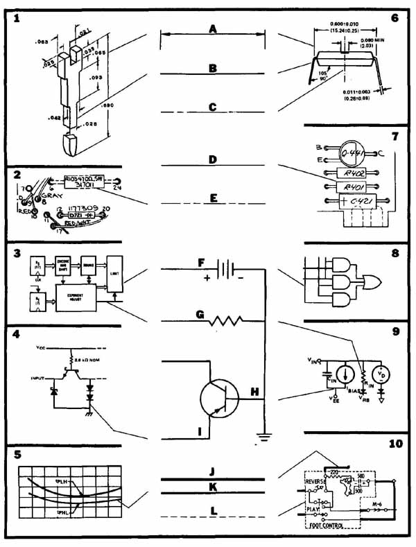
FIG. 13 Line key for electronic drawings.
J, K. Emphasis Line, FIG. 13 (5, 10): A thicker line (10), used when a particular flow line (or symbol) on a diagram needs to be emphasized; also found on graphs (5).
L. Dashed Line, FIG. 13 (10): Used on electronic diagrams (10); also used to indicate mechanical link age or connection between components (10, foot control switch). JIC Electronic Standard EL—71 states that “Discrete items or the equivalent circuit contained within a packaged (plotted) unit shall be shown within dashed lines on the elementary diagram. For clarity, individual circuits within the pack age may be separated and each enclosed within dashed lines.”
The dimensioned IC package in FIG. 14 uses a variety of conventional mechanical lines, including visible lines, object lines, centerlines, dimensioning lines, extension lines, and leader lines.
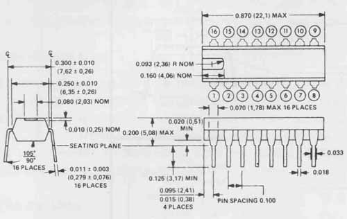
FIG. 14 Dimensioned orthographic drawing of integrated circuit package. ( Texas
Instruments, Inc.)
Sketching
Sketching is the primary means of graphic communication among engineering personnel. The ability to sketch is an essential skill for all drafters, designers, and technicians. Sketching is used to convey original design ideas from the designer to the drafter and to clarify design alternatives. Sketches are also used to lay out diagrams so that they can be digitized on a CAD system. In FIG. 15 the CAD operator is digitizing a schematic diagram sketch.
In general there are three types of sketches: pictorial, orthographic with or without dimensions, and diagramic. The use of graph and grid paper speeds the construction of any sketch and enables it to be used as a digitizing layout since all digitizers are based on a grid pattern.
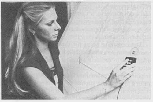
FIG. 15 Drafter digitizing sketch. (Courtesy Bausch & Lomb Interactive
Graphics Division)
As a designer, sketching allows you freedom to try alternative positions of components and trial layouts for electronic diagramming. Sketch with thin, light construction lines, starting with box shapes. Darken the shapes only after the design is complete. Sketch center lines and lines establishing symmetry in the early stages to locate important features of the design or layout. Block in circles and circular arcs before drawing the curve, using the diameter as the controlling dimension.
Isometric sketching is used for clarifying the design of three-dimensional parts and objects and can aid in establishing the proper view orientation for a pictorial or multiview drawing.
FIG. 16 shows the original sketch and the finished electronic diagram. The sketch was completed on vellum with a fade-out grid.
Lines
Lines and their relationships are the most important parts of all engineering disciplines. This is particularly true of electronic drafting and design, where a vast majority of drawings are two-dimensional diagrams primarily made up of vertical and horizontal lines and symbols. Block diagrams are composed of straight, perpendicular vertical and horizontal lines. Logic, schematic, and wiring diagrams are primarily constructed with straight lines except for accompanying symbols and components.
A line is considered to have length but no width. A straight line is the shortest distance between two points and is implied when you speak of a line. A line that bends is called a curve.
Parallel lines are equally spaced along their entire length, neither becoming closer together nor further apart. The symbol for parallel lines is ||.
Perpendicular lines lie at an angle of 90 degree to one another and can be intersecting or nonintersecting.
Horizontal and vertical lines are easily constructed with the straightedge and a triangle or a drafting machine.
Curved Lines
Arcs, circles, and other curved lines require special line- work techniques. The compass lead is fixed in thecom pass and cannot be rotated. Noncircular curves are drawn with an irregular curve as a guide, but the guide only fits the curve for a short distance. Moreover, a curve must be drawn equal in width to the straight lines in order to produce a uniform drawing.
The use of the compass and the irregular curve to create dark, consistent linework is typically one of the most frustrating aspects of mastering drafting. Circle, ellipse, and other curved templates are available in most standard sizes. These excellent tools can be applied to many of the constructions. Unfortunately, they are limited in sizes and shapes and are relatively expensive. It is suggested that you wait to practice curves with templates until you have mastered the compass and irregular curve.
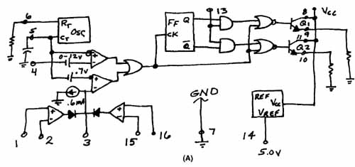
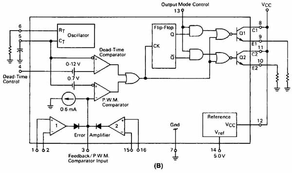
FIG. 16 Original sketch and completed schematic.
The Bow Compass and Dividers
A good bow compass and dividers are essential to the accurate construction of all forms of engineering drawings. (See Figs. 36, 37, and 38 for examples of compasses and dividers.) A bow compass has a center wheel that is used to set and hold the spacing between the center point and the lead. Dividers do not have a center wheel and are used to quickly set off measurements from one view to another, which is extremely useful in the construction of electronic diagrams.
The centering point for the compass is either a tapered point or a short needle point projecting from a wider shaft to create a shoulder. The needle point is better for beginners because it provides a stop to limit the point’s penetration into the paper. A small piece of drafting tape can be applied to the drawing at the center of the arc or circle to be constructed, and the centerlines can be drawn over the tape. Using this method will restrict the compass point from penetrating the drawing medium while providing a stable, secure centering point from which to swing an arc or circle. Circles smaller than .50 in. (12.7 mm) are much easier to draw with a template than with a compass. A compass is confined to odd sizes and large circular shapes. Electronic templates contain circle shapes for such components as transistors and meter encasements.
Dividers have two identical tapered metal points, one of which can be replaced with a piece of 4H lead. This lead can be used to set off dimensions instead of the two metal points, which tend to mar the drafting medium.
The compass lead should be a piece of the drafting pencil lead (same grade lead). Then both straight and curved lines will be drawn with the same lead, and it will be easier to maintain uniformity. The lead is secured in the compass with about 3/8 in. (9.52 mm) exposed and is sharpened with a sandpaper block. Use care while sharpening to keep the line through the point and the lead perpendicular to the sandpaper. Make a flat cut that leaves an oval surface, called a bevel. The bevel should be about three times as long as the diameter of the lead. The resulting point is chisel shaped and should have about the same taper, when viewed from the side, as the cone shape of the drafting pencil. Do not adjust the lead in the compass after it is sharpened because it is almost impossible to properly reposition the chisel shape. Adjust the centering point so that the midpoint of the needle point is even with the end of the lead. The beveled end can be on either side of the lead. Both sides of the lead may be beveled to create a thin, dark curve with a point that is longer lasting. The compass can now be adjusted to the required radius and used to draw a circle or arc. Locate the center of the required circle or arc and draw a horizontal construction line. Set a distance equal to the radius of the circle or arc to be drawn. Then set the compass to this distance and draw a construction circle.
Measure the diameter of the circle. The reading should be twice the given radius. To get an accurate diameter reading, make certain the measurement is taken along a line that passes through the center point of the circle. Any difference between the measured diameter and twice the given radius is twice the error of the compass setting. The width of the line that will be drawn is determined entirely by the width of the lead (thickness of the bevel) at the moment. As a circle is drawn, the point begins to shorten and the line to widen. This tends to make the line thicker, but may also create a fuzzy line. To get a crisp, clean, dark line, keep the bevel very sharp, and draw the line thin and dark by rotating the compass a couple of times. Then re-sharpen the lead and draw another line touching the first line but slightly larger or smaller, depending on the required dimension and the size of the first line. This procedure always gives a sharp, clear line. A longer taper on the lead holds a line width longer.
Irregular Curve
Noncircular curves require the use of an irregular curve to make smooth, printable lines. Examples of noncircular curves are the ellipse, an angular view of a circle, and the helix. Irregular curves are manufactured in a great many shapes and sizes, and it is a good idea to have a variety of types from which to choose.
Curves drawn with irregular curves are usually determined from a series of plotted points, as in FIG. 17. Then a curve is drawn that includes all these points. Good results can be obtained if the following steps are taken:
1. Sketch lightly by hand a smooth line that includes the plotted points. It is easier to set the irregular curve to a line than to a series of points.
2. Set the irregular curve so that it fits to a part of a line, as shown in FIG. 17, usually a minimum of four points.
3. Draw the line that fits the curve, but stop one point short, before the end of the fit. In FIG. 17, A fits from point 1 to point 5 but is drawn from 1 to 4. B fits from point 3 to point 9 and is drawn from 4 to 8. C fits from point 17 to point 23 and is drawn from 18 to 22.
4. Reset the irregular curve to fit each next part of the curve and include the last portion of the already drawn line. This overlapping will give a smoother curve.
Neater work results if the sketched curve and the first series of fitting the irregular curve are all done on a tracing paper overlay. When using an overlay, mark the ends of each segment of the line as it fits the irregular curve so that the same fits can be used in the next step. When all fits are made, place the tracing paper overlay under the drawing and carefully align the curve under the plotted points. Trace the curve onto the drawing using the irregular curve fits marked on the overlay. This technique has two advantages. First, all the fitting is made on a throwaway paper so that erasures can easily be made without erasing the plotted points. Second, the accuracy of the fit can be seen before the final drawing of the curve, when the overlay is positioned under the drawing.
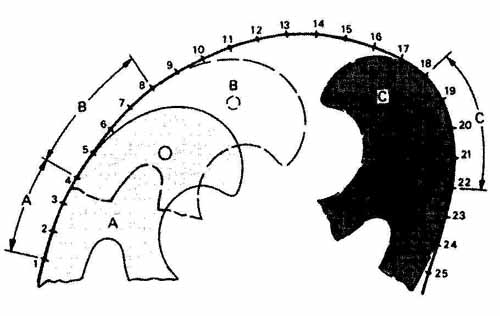
FIG. 17 A noncircular curve drawn with the aid of a French, or irregular,
curve.
The overlay technique is particularly valuable when the curve is symmetrical. For example, an ellipse has four identical curves; two are mirror images of the other two. All are symmetrical about the major and minor axes. It is only necessary to fit one of these curves and then to duplicate this fit on the other three.
The plotting of the points of an irregular curve is particularly important if a smooth curve is to result. A small error in the position of a point can easily cause irregularities in the curve. The plotted points should be spaced farthest apart where the curve is straightest and closest together where the curve is the sharpest.
In FIG. 18 the drafter is drawing a curved line with a French curve and technical pen. Note that the pen is held almost vertical to the work. A slight angle away from the irregular curve edge must be maintained in order to prevent the ink from seeping between the plastic curve and the paper.
Graphical data are sometimes represented by non- circular curves, as in FIG. 19. Graph lines are normally plotted on a given grid pattern on rectangular coordinate paper, representing two variables. The horizontal coordinate is usually plotted as the independent variable and the dependent variable is plotted vertically. The horizontal or X axis is called the abscissa and the vertical or Y axis, the ordinate. The origin of data may be set in a number of different places on the graph, such as the lower-left corner of the graph with 0—0, as in FIG. 20, or the center, as in FIG. 21. The curved graph lines were plotted with this technique and drawn with an irregular curve.
In FIG. 22 a chart has been created with a CAD system. Charts and graphs completed on CAD systems are easily plotted with small multi-pen plotters, as shown in FIG. 23.
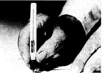
FIG. 18 Inking with an irregular curve and a technical pen. (Courtesy Koh-i-Noor
Rapidograph, Inc.)
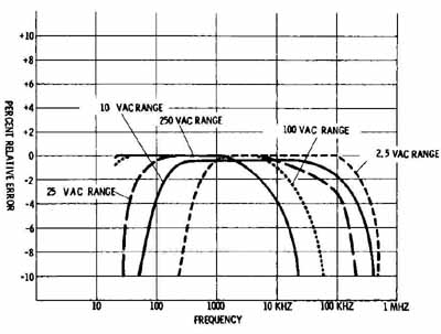
FIG. 19 Noncircular curves plotted on a graph. (Simpson Electric Co.)
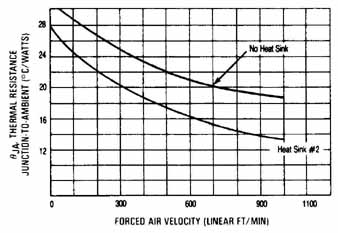
FIG. 20 Thermal characteristics of 68-pin leadless package. (Motorola, Inc.,
Semiconductor Products Sector)
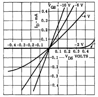
FIG. 21 Voltage versus current characteristics for an FET.
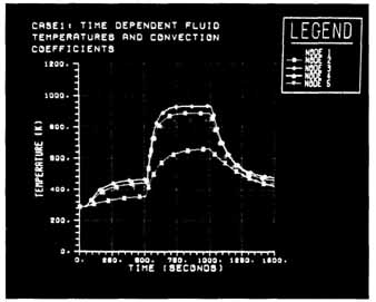
FIG. 22 CAD-generated chart.
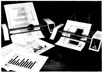
FIG. 23 Houston Instrument’s PC Plotters. ( Houston Instrument)
REVIEW QUESTIONS
1. True or false: A solid, medium-weight line is used to show the hidden portions of an object on a multiview drawing.
2. Diagram lines represent ( ) on an electronic diagram.
a. object lines c. future circuits
b. circuit flow lines d. dimensions
3. A cutting-plane line shows where the object is to be ( ).
a. dimensioned c. sectioned
b. projected d. broken
4. True or false: CAD-generated lines can be plotted at any desired weight (thickness) depending on the system software capabilities.
5. True or false: The lineweights for an electronic symbol and circuit flow line should be different thicknesses.
6. Which of the following is not considered an electronic diagram drawing?
a. block c. pictorial
b. schematic d. logic
7. List four typical uses for a sketch.
8. Which type of inking pen is used throughout industry?
a. ruling pen c. inking drop compass
b. technical pen d. felt pen
9. How are lines used as symbols?
10. Technical pens should be held ( ).
a. at a 60 degree angle c. at a 67 1/2° angle
b. almost horizontal d. almost vertical
11. True or false: The exact thickness of a line on an electronic diagram defines its use and is covered by an ANSI Standard.
12. Define the following terms:
- visible line
- technical pen
- diagram line
- section
- dimension line
- leader extension line plotted points
- break line
- cutting-plane line
- arrowhead
- hidden line
- centerline
- component outline
- emphasis line
PROBLEMS
1. Draw the block diagram of the garage-door opener control shown. Use all uppercase lettering. Block lines are to be .7 mm thick and flow lines are to be .5 mm thick.
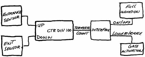
PROBLEM 1 Block diagram of a garage-door opener.
2. Draw the flow diagram of the simple computer shown. Use upper- and lowercase lettering. Boxes are to be .7 mm and flow lines .5 mm thick.
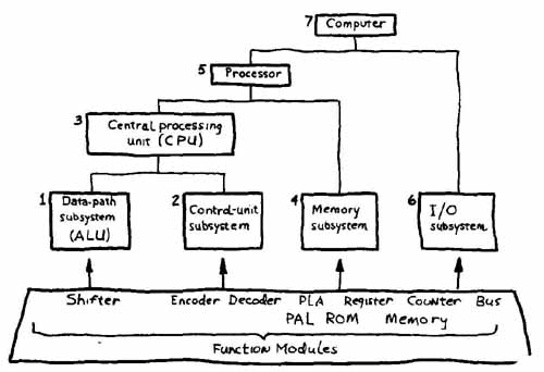
PROBLEM 2 Flow diagram of a simple computer.
3. Draw the following lines 3 in. (75 mm) long.
- phantom diagram
- cutting plane
- centerline break
- section
- construction
- circuit
- hidden
- leader
- extension object
- dimension
- flow
4. Redraw the diagrams in Figs. 3 through 8 as assigned. Use proper lineweights and lettering.
5. Sketch the diagrams in Figures 3 through 8 as assigned. Use proper lineweights and lettering.
6. Using the graph in FIG. 20, plot the following curves:
Curve 1 Curve 2 Curve 3
x y x y x y