.
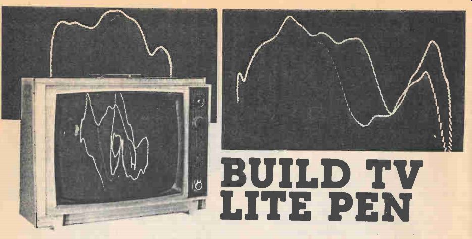
Old TV Set Adds Video Excitement to Your Stereo Setup
If you're a dedicated stereo sound listener who likes to experience the ultimate in Sounds; if your home stereo gives you lots of sonic pleasure but you'd like even more, this TV Lite Pen can provide an extra Zing of visual lift every time you turn on your (heavy) Sound System.
It works by displaying dancing, pulsating light patterns on an old TV screen (or a new one) set up so that the changing light rays move and dance across the screen in synchronism with the sounds from both stereo channels.
So-called light organs have been around for a long time, but they just show gently pulsing lights (or two, or at most three or four) colors through translucent (milky) glass or globes. They respond only to changes in audio volume, and rather slowly at that.
Like an Oscilloscope
You may have seen an oscilloscope hooked up to a microphone to display the variations produced by voice signals, or of music. Well, TV Lite Pen is much like an oscilloscope, the workshop of lab instrument which displays changing voltages on its screen. But the 'scope usually shows a single horizontal wavetrace moving in accordance with a changing (or steady) voltage. TV Lite Pen blends both audio channels of stereo signals to give you a visible display of what's going on while you hear the pulsing, throbbing crescendos (as well as the quieter parts) of your favorite music.
TV Lite Pen is an adapter which turns just about and old (or new) TV set into a special oscilloscope for stereo sounds. It shows the myriad sound patterns on the screen of the set. These are called Lissajous patterns.
About Lissajous Patterns
Going back to basics, a Lissajous pattern is an oscilloscope display of two signal inputs to the 'scope inputs. The most usual 'scope display is just what ever is fed to the vertical input of the instrument, which is then moved across the screen by an internal sweep signal (usually 60 hertz). But Lissajous patterns need signal inputs to both scope inputs, the horizontal as well as the vertical. Lissajous figures are 'scope displays of two signal inputs to the display screen-not just the usual vertical input signal which we use when we want to measure the amplitude of a voltage or watch how its amplitude changes with respect to time (the most common use of the oscilloscope). With signals going to both the vertical and the horizontal inputs of an oscilloscope we can measure the relationship with respect to time (it's called phase) between the two signals.
For example, if a known signal is applied to the horizontal input and an unknown signal is applied to the vertical input, the resulting Lissajous pattern shows the phase relationship of the two signals.
Lissajous patterns can also be used to measure frequency. A known frequency is applied to the horizontal amplifier and an unknown frequency is applied to the vertical. By counting the number of tangency points at the top and at one side, a ratio of unknown-to-known frequency can be obtained. By multiplying the ratio times known frequency, you can determine the frequency of the unknown.
A Simple Light Pattern
The figure at the top of the page shows a lissajous pattern for two sine waves. Numbers have been assigned to corresponding voltage points of the two signals. Extensions of these points are brought to the screen. The intersection of corresponding numbered lines is the position of the electron beam at that instant of time. In this case the two sine waves are in phase.
In the figure below, voltage/time relationships are different; corresponding voltage points are 45 degrees apart. Therefore the waveforms are 45 degrees out of phase.
A continually shifting Lissajous pattern results when the phase relationship between the two input signals is constantly changing. The more complex the pattern (resulting from a frequency ratio having large numbers, such as 17/13) the harder it is to interpret.
But since were not trying to analyze the pictures, we can just lean back and enjoy.
---------------------
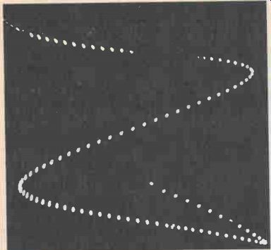
Figure 1. Patterns like these appear from moment to moment on the TV
screen when it's being driven by signals from music. Since they don't
fade out right away (persistence of screen, as well as persistence of
our vision) you'd have to use motion pictures (or TV tape) to break this
composite picture down into individual frames.
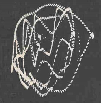
Figure 3. This light pattern would be produced by a slightly more complex
(but not much more) pair of sound signals.
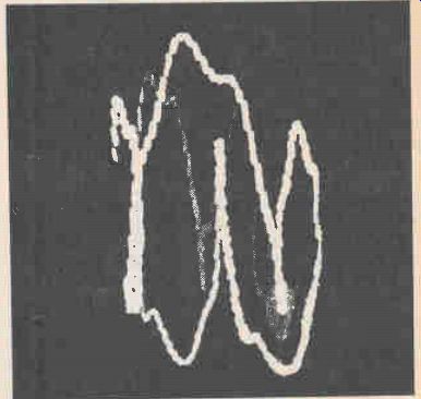
Figure 2. This rather simple light pattern (Lissajous figure) is about
as simple a visual display of signal input to TV Lite Pen as you could
expect. It shows a very slow, low frequency signal on the horizontal
input being modulated (changed) by a slightly faster (higher frequency)
sound on the vertical.
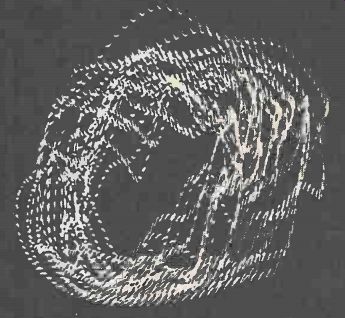
Figure 4. This pattern drawn by TV Lite Pen shows nearly identical but
rather simple signals going to both vertical and horizontal inputs. Perfect
matching between the two channels would provide a single slanting line,
as in Figure 5.
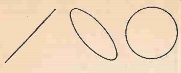
Figure 5. Simple Lissajous figures are produced when the identical signal
(left) or almost the same (middle and right) signals are applied to the
two (horizontal and vertical) inputs of a scope, or a TV screen.
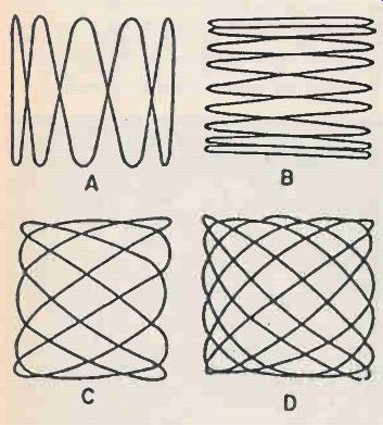
Figure 6. More complex figures (still Lissajous, however result when
a simple sine wave is fed to the horizontal (sweep) input of a scope
along with exactly-related signals on the vertical (signal) input. (A)
shows signals five times the frequency of the sweep; (B) input at vertical
is 1/9 the horizontal sweep; (C) shows what happens when signal is 5/3
the sweep; at (D) is shown the result of 6/5 ratio mixing.
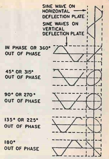
Figure 7. If a mono signal is fed to both channels (of a scope or to
TV Lite Pen) the slant line (below top right) results. Adjusting gain
of one or both channels is required to get 45% slant, other Lissajous
figures will show as gain and phase are varied. These wave forms are
very simple compared to the waveforms of music. Simple input signals
result in simple pattern. Complex (music) waveforms make complex waveshapes.
-----------------------
How it works
By connecting the parts of an old TV set so that the output from one channel of a stereo set (for example, the left) drives the electron beam of TV tube vertically, and the output of the stereo set's right channel drives the beam horizontally, we can use the TV set to display Lissajous figures created by the signals from the two stereo channels. What we do is make the old TV set/stereo amplifier combination into an uncalibrated oscilloscope. Then we feed it the two signals without worrying what they mean.
Putting it Together
Begin with an old television set. You can use one in which the tuner, IF, and sound sections do not work since they will not be used. You'll also need an extra deflection yoke from another set. Most of the older tube-type black and white sets have yokes the same size. As long as the extra yoke will fit over the neck of the set's picture tube it can be used. A junked TV is the best place to look. You must also have a stereo set with amplifiers capable of producing 12-15 watts of output power per channel. Even better is a spare (second) stereo set. This will insure better results and will also allow you to adjust the tone, volume and balance controls to the TV set without upsetting your listening pleasure, by changing the volume setting while you listen.
Begin by removing the back from the old TV set.
Disconnect the socket from the rear of the picture tube. Loosen the clamps holding the deflection yoke and slide it off the neck of the tube. Do not disconnect any of the wires from the yoke since it is part of the circuit for putting the beam on the screen. Secure the old yoke to the chassis of the TV somewhere out of the way, taking care in seeing that it does not short circuit.
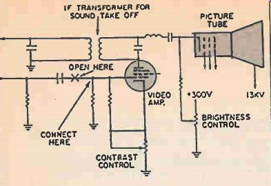
Figure 8. This schematic diagram shown a typical video amplifier stage
for a tube set of the Sixties.
Similar setup is found in later, transistorized TV sets. The video (picture) input signal to the cathode-ray tube (CRT) is disconnected, and TV Lite Pen's oscillator can be hooked in its place to make TV Lite Pen do extra tricks.
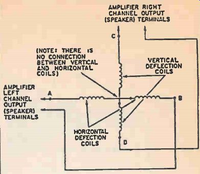
Figure 9. This is the basic hookup for TV Lite Pen. Two CRT deflection
yokes can be used.
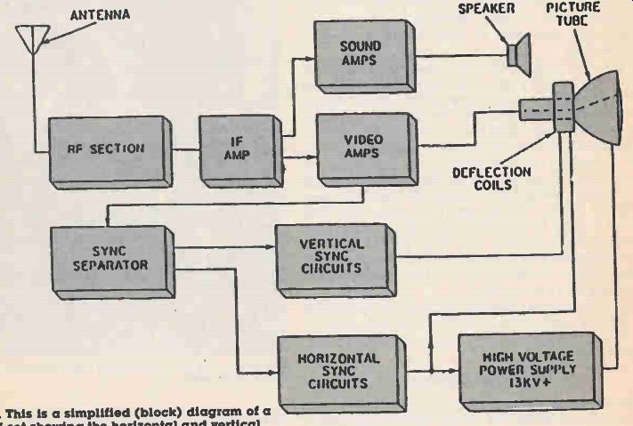
Figure 10. This is a simplified (block) diagram of a typical TV set
showing the horizontal and vertical sweep (signals) currents being derived
from the synchronizing signal coming from the TV transmitter. The horizontal
and vertical sweep (signals) drive the horizontal and vertical deflection
yokes of the receiver.
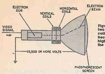
Figure 11. Here's a typical CRT (TV tube) with its two deflection yokes;
the horizontal and vertical coils. The old deflection yoke of the TV
set is used because it's part of the circuit which produces the high
voltage needed to pull the electron rays from the electron gun (rear
of CRT) to the screen.
Preparing the Deflection Yoke.
There are two coils in the CRT deflection yoke of a TV set. One is called the horizontal and one the vertical.
Each of these two coils is divided into two sections, and we must eliminate any extra parts such as a small resistor or capacitor which are often connected to one or both of the yokes. They are usually connected to the midpoint of the horizontal coil or vertical coil.
Simply remove any resistor or capacitor connected to any parts of the yoke, and if this separates the two sectional parts of either the horizontal or vertical coil, put a jumper between the two sections. Check with a voltmeter to be sure which terminals are connected (through the two coils) together. Mark them in some way so that you'll know which two leads of each coil are connected together (through each coil). Solder two three-foot lengths of speaker wire to the terminals of the vertical and horizontal coils.
Assembling Lite Pen
Take the CRT yoke and slide it on to the neck of the picture tube securing it with a clamp. Return the socket to the back of the tube along with any magnets that may have been removed. Put the magnets back exactly where they were. (Adjust to center beam, later). Route the speaker wire out the back of the TV set as you put the cover back on. Run wires from the speaker outputs on your stereo to the TV set and connect the two sets of wires together using a terminal strip.
You are now ready to test it out. Leave your stereo off and turn on the TV set. After warm up a small dot should be visible in the middle of the screen. Adjust the magnets, if any, to center the beam. If necessary turn the brightness control up or down. Now turn on the stereo set and turn up the volume slowly until you start to notice the dot moving. By adjusting the balance control you should be able to make the dot move about an equal amount horizontally and vertically. It may be necessary to disconnect the speaker in order to move the beam enough. Adjust the brighness for a pleasing light level without burning the screen phosphor. Low bass notes will show up as rotating circles. Each tone has its own pattern which intensifies with the volume.
Now that you are finished sit back and enjoy the added dimension of the music TV in a dark room. It will provide you with many hours of listening and viewing pleasure.
Figure 12. Typical deflection yoke mounted on the neck of TV tube.
Other Light Displays
Once your Lite Pen is working you may want to add an extra circuit which will strobe the moving pattern on and off, making a more unusual and interesting light display. By connecting the output of an oscillator to the grid of the TV set's video amplifier tube you can turn on and off the electron beam in the picture tube. This will produce dots and dashes as the beam is moved around on the screen. The effect is quite pleasing. A stop-action type of display (called "strobe") is only one interesting improvement you'll see.
---------------------
PARTS LIST FOR STROBE CIRCUIT FOR LITE PEN
C1 -100uF. 16VDC electrolytic capacitor
C2, 6-.02 or .22uF capacitor
C3, 7-.01-uF capacitor
C4, 8-.1-uF capacitor
C5, 9-1-uF capacitor
D1, 2, 3, 4-rectifier diodes, 30 PIV or better any amperage (Radio Shack 276-1626 bridge rectifier will do fine)
R1, 4-10,000-ohm resistor
R2, 3-47,000-uF resistor
R5 -1000-ohm resistor
R6, 7-250,000-ohm potentiometer (or 500,000 if 250,000 not available)
Single pole, 4-position or more - rotary switch (Radio Shack 274-1386 or equiv.) Q1, 2-General-purpose PNP silicon transistors, HEP 242 or similar T1 -Power transformer, 117 VAC primary 6.3 VAC secondary, any amperage (Radio Shack 273-1384 will do fine).
PARTS LIST FOR TV LITE PEN
TV receiver-which has light (raster) on the picture tube. It need not have a working tuner or IF section, nor sound.
Picture tube deflection yoke--in working condition.
(Most are-this is a part that rarely fails in TV sets.) Speaker wire-8-10ft.
Stereo amplifier or receiver-preferably 12-15 watts or more per channel.
Misc. -Solder, wire, switches, etc.
-----------------------
Simple Oscillator
The added circuit is a simple two-transistor oscillator. The switches and potentiometers allow you to select different dot line lengths and frequencies. By connecting the output of the oscillator to the grid of the video amplifier you force the tube alternately into conduction and cutoff.
The oscillator and power supply are not critical and can be constructed any way that is convenient, as long as safe construction practices are used. The circuit in the prototype was built on a terminal strip using point-to-point wiring and then mounted inside the TV. Almost any general purpose PNP transistors can be used for Q1 and Q2.
If you can't get a schematic of the TV set you are using the best way to locate the video amplifier tube is to look at the tube placement chart (usually on the side or back of the TV) and find the tube which is labeled Video Amp. If the video amp tube also contains other elements in the glass envelope you will have to trace down that part of the tube which has its plate connected to the sound trap transformer (usually a metal can type) and its cathode connected to the contrast control. This may vary slightly in your set.
Once you have found the video amplifier cut one of the leads of the capacitor going to the grid and replace it by connecting the oscillator output to the tube in its place, (see the schematic). Connect the negative lead on the oscillator's power supply to the TV common ground.
Now's the Time
Now you are ready to test the circuit. Look it over for any wiring errors. Set the potentiometers to maximum resistance and set the rotary switches at the .01 uF capacitors. Turn on the TV set and get a music display on the screen. Turn down the brightness control until you can no longer see the raster (white lines). Turn on the strobe oscillator and adjust the brightness control as needed. The display should be chopped up into little line segments. By adjusting the controls you can get different line lengths and frequencies -anything from star-like dots to a pulsating array of stopped action traces.
Now you can lean back and enjoy your TV light organ which will amuse and amaze your friends for many evenings ahead.
Also see:
More from EH magazine: Tandy's Radio Shack
Adapted from: Electronics Handbook--Spring 1987