One-evening Project Provides Low-Cost Universal Tool for Finding AM, FM, or TV Troubles
Probably the most sure-fire way to find the problem in any set you're repairing is to start checking in those parts of the circuit where there is no trouble. You then go backward through the circuit until you've reached the point where it isn't working. The same trick can work frontwards, letting you trace a signal through a circuit until you reach the point where it disappears.
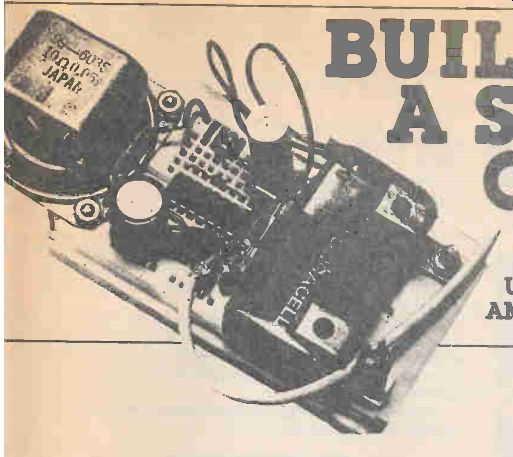
Here's a handy aid for troubleshooting in the frontwards fashion, a signal tracer with a great deal of input sensitivity called Signal Chaser.
Built-In Demodulator
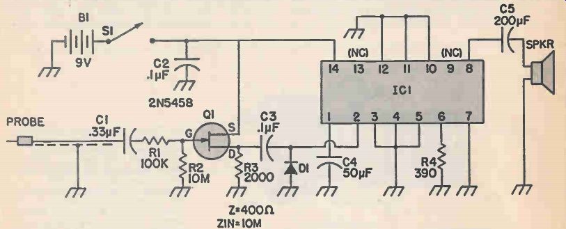
An ordinary amplifier could help you find signals in the AF (audio frequency) range but the Signal Chaser can do more. D1, a 1N914 diode, acts as a de-modulator, much like the diode in a simple crystal set-style radio, to demodulate AM (amplitude modulated), RF and IF signals directly to audio (or whatever the carrier is modulated with). On FM and PM (frequency modulated and phase modulated) signals, the diode acts as a slope detector, giving a suitable, if low-fidelity, audio output.
----------------
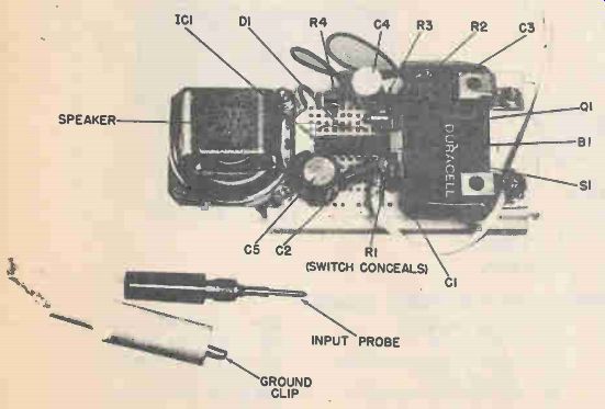
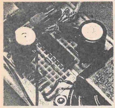
Our Signal Chaser was built using a solderless breadboard and, as you can see, it made for a neat component arrangement. If you follow this photo, be certain you don't forget about R1 which connects to the Gate of G1 and to C1--it's really there, it's Just hard to make out in the picture! Signal Chaser should go together quite quickly, so if you start it after lunch you should be chasing your first signals before the dinner bell.
Signal Chaser has a high impedance input that is close to 10-Megohms. It will draw very little current and so will not usually load down the circuit under test.
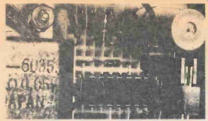
Solderless breadboard material is arranged with the holes about 1/10 inch apart. As you can see, this Just fits the spacing of the IC's leads and of most modern components.
--------------
High Impedance Input
The one feature of this circuit that really makes it shine when compared to most signal tracers is its high impedance input. The input impedance of the Signal Chaser is close to 10-Megohms. This is due to the use of a JFET (Junction Field Effect Transistor) for Q1.
Q1, a siliconix 2N5458 or similar P-channel JFET, is configured as a high-to-low impedance converter with an input impedance converter with an input impedance determined mostly by the value of R2, 10 Megohms.
Capacitor C1 blocks DC but passes AF, RF and IF signals. Resistor R1 limits the input current to Q1.
A high input impedance means that for a given signal voltage, very little current is drawn by the Signal Chaser. This means that under almost all conditions, the Signals Chaser cannot load down the circuit you are troubleshooting.
Plenty of Output
The output of Q1 alone would be enough to drive a high impedance earphone, but keeping one in your ear while busy probing a suspect circuit can be, to say the least, inconvenient.
Instead, the output of Q1 (after demodulation) is coupled to the input of IC1, an LM380N audio amplifier. IC1 provides enough drive to power even low-impedance speakers. around 8-ohms, to a good, healthy volume.
Capacitor C5 provides DC decoupling between the speaker and the output of IC1.
Solderless Construction
The entire circuit can be built up on a small solderless breadboard like the one shown (a Continental Specialties Corporation board) or a similar one from Radio Shack for under $7.00, in almost less time than it takes to tell.
There are three tricks you can use here.
PARTS LIST FOR SIGNAL CHASER
B1 -9-VDC battery
C1 -.33-uF capacitor
C2 -.1-uF capacitor
C3 - 1-uF capacitor
C4 -50-uF capacitor
C5 -200-uF capacitor
D1 -1N914 diode
IC1 -LM380N audio amplifier
Q1 -2N5458 JFET
R1 - 100,000-ohm resistor
R2 - 10-Megohm resistor
R3 -2000-ohm resistor
R4 -390-ohm resistor
S1 -SPST switch
SPKR -8 ohm speaker
MISC -Breadboard (Continental Specialties or Radio Shack.)
For one, I used a pair of zig-zag mounting brackets (from the local Radio Shack) as battery hold-down clips. The mounting holes in the CSC EXP350 helped make this especially easy. At the far side of the breadboard the mounting holes there happened to match exactly the holes on a small speaker I had on hand, and I was quick to take advantage of it. My third trick was to solder stiff wire (resistor leads I cut off some of the resistors in the circuit) to the breadboard end of the shielded probe cable. You may also want to use "headers," available from several sources and many parts stores for under a dollar a strip.
The rest of the assembly is fairly straightforward.
Follow the lead of my layout, as shown in the photograph, when you lay out your own Signal Chaser --whether on a solderless bread-board, a PC board or whatever method you use.
Solderless Breadboards
In case you haven't tried solderless breadboards before, you may not know how easy they are to work with. The holes in the face of the breadboard are arranged on .1" centers (1/10th of an inch apart), which happens to be lead spacing on standard DIP (dual in-line package) integrated circuits and most other modern components.
The center channel (.3" wide) is just right for ICS to straddle. On each side of the center channel are groups of five holes (columns if you view the breadboard as widest on the horizontal , with the center channel running left to right). Behind each group of five holes is a spring clip with slits between the hole positions to allow a lead inserted into any one hole to be grasped firmly and independent, and interconnected with anything grasped at any other position in the group.
Each five-position terminal can be interconnected with any other by simply using hookup-wire jumpers.
The separate rows (at the top and bottom) are connected across their entire lengths and can be used for power or signal busses. I use them to carry the battery plus and minus lines.
Using Signal Chaser
For most run-of-the-mill signal tracing, clip the probe cable shield to a circuit ground near the area you're testing and touch the probe to each side of the signal path near each active or passive device in the signal path. Start at the front end and work your way to the output, if you like - but skipping a few stages on the chance they'll work can also help you localize a problem.
The high impedance of the Signal Chaser input means high sensitivity, which lends it to some useful applications. You can attach a coil of wire or a magnetic tape head to the input to inductively probe circuits and devices. You can "listen" to the magnetic stripe on the back of your credit cards, amplify a telephone conversation or pick off the signal on your transmitter's modulation transformer.
Or attach a photocell to the input and listen to the sounds of light bulbs, LED readouts. the sun, street lights and then some.
Signal Chaser--not only a good introduction to solderless breadboarding, but once it's built you may find it to be one of the handiest gadgets in your electronic bag of tricks-of-the-trade. Have fun and chase those signals--and those problems--down!
Also see: Buying Electronic Parts
More from EH magazine: Tandy's Radio Shack
Adapted from: Electronics Handbook--Spring 1987