Everybody knows the VOM (volt-ohm-meter) is the basic instrument of electronics, and it certainly is the first one everybody must learn to use. Most repairs of radio, telephone and other fairly simple devices can be done using a VOM. But today's electronics have many circuits that put out rapidly-changing signals.
Such signals can't be checked with a meter, because the meter's needle just can't respond to signals that change many times a second.
Fast-Changing Signals
For fast-changing signals such as waveshapes and digital signals (computer circuitry, especially), we need an instrument that responds to and can show us signals changing anywhere from a few times a second to millions of times each second, (megahertz). That instrument is the oscilloscope, usually abbreviated to "scope". It's very similar to a black-and-white TV set. In fact the first TV sets were oscilloscopes with some of the circuits changed to display signals moving across the screen 60 times a second and up-and-down vertically about 500 times a second.
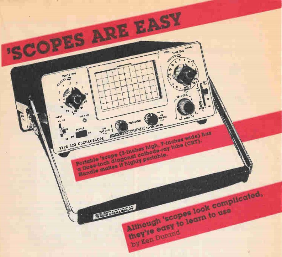
Using a scope is not much more difficult than using a VOM (or a vacuum-tube voltmeter; VTVM). If you study the pictures shown in this article, you will be able to set up a standard scope and adjust it to display waveshapes in typical electronic circuits such as radios, TV set and many computer circuits. This will let you analyze what's happening (or not happening, as the case may be) in those circuits. In turn this will help you figure out what's wrong in those circuits, and thus what needs to be done to repair them.
Like a TV Set
Although the controls on the front of most scopes look impressive, even formidable at first, after you examine them carefully you'll find that many, in fact most of the controls you'll use most of the time, are very similar to the controls and adjustments on a black-and-white TV receiver.
The first control on a scope (as well as TV set) is the On/Off control. This may be a separate switch, but it's often combined with the Intensity control. On a TV set this would be marked Brightness usually. And the extreme counter-clockwise of this control, if combined with the Power switch, is the Power Off position.
When you first turn the scope on, it may take a minute or two for it to warm up. This is true even if it's a modern instrument and uses only transistors and other solid-state devices, instead of the vacuum tubes earlier scopes (and TV sets) used. This time lag is because scopes still use one vacuum tube, the cathode ray tube (CRT) to show the picture. And the CRT, being a vacuum tube, has a filament which takes a finite time to warm up, unlike solid state devices, which are ready to go as soon as the power is turned on.
Some scopes have the On/Off switch combined with a different control which adjusts the intensity of a graph-like overlay in front of the CRT. This overlay glows amber, and is adjustable. It lets you measure the size of waveforms by comparing its graphic lines (vertical and horizontal) with the size and shape of the waveforms. This graph-like overlay is called a graticule.
When you first adjust the Brightness control you should set it fully clockwise. That's because it's easier to find the scope trace when it's brightest, at first.
Once you've got the trace visible on the screen you should turn it down so it's not at full brightness. This is to keep from burning a hole in the phosphor coating which is on the inside of the CRT faceplate.
-------------------
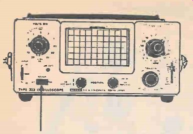
------- Figure 1. Arrow indicates Power On/Off switch. It's often
combined with the Intensity control, but on this scope they're separate.
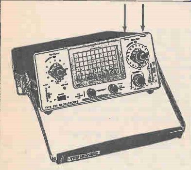
Figure 2. Intensity control is usually grouped with Focus and other
display controls right under the cathode ray tube (CRT) face. Because
this portable scope has less panel space than most others, Focus and
Intensity are (hidden) atop the screen (at right).
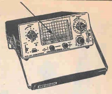
Figure 3. Vertical and horizontal lines are overlaid on Graticule
(vertical and horizontal divisions) on the face of the CRT to permit
measuring voltages and time periods of waveshapes.
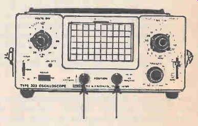
Figure 4. Horizontal and Vertical Position are easy to adjust. Each
is a dual control, and normally controls position. When pulled Out
they adjust Horiz. or Vert. Gain.
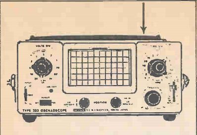
Figure 5. After electron beam has been centered, Intensity control
is adjusted to prevent burning a spot in the face of the CRT. Focus
and Intensity are adjusted one after the other since they interact.
Figure 6. Vertical Input is used for the video signal to be displayed.
Figure 7. Time/Div. is one name for control which adjusts timing for
video (vertical) input signal.
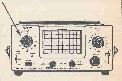
Figure 8. Volts/Div. switch and vernier (fine) adjust vertical size
of displayed waveshape. This control also has Calibrate position. This
puts signal of known amplitude (from internal generator) on screen
to permit accurate voltage measurements.
------------
If you don't see a trace on the screen right away, the next step is to adjust the Centering controls. These will usually be labeled Horizontal Position and Vertical Position, or Hor Centering and Vert Centering. Rotating the Vertical control moves the spot up and down, and the Horizontal moves it sideways. Set each of the two controls to its center position, approximately, and then move first one, then the other, back and forth around its center position, meanwhile watching the screen carefully for any hint of light. It many require that you jockey the two controls back and forth a few times to pull the light spot onto the CRT face.
After the beam has been placed near the middle of the screen, adjust the Intensity as low as you can set it and still, see the spot easily. This is to keep from burning a spot in the middle of the CRT. Now adjust the control marked Focus. This is usually right next to the Intensity control. You simply rotate the Focus control to get the smallest spot. When the Focus control is moved in either direction away from correct (smallest) focus, the spot will get larger and at the same time will also get fuzzier.
In most uses of the scope you'll want to get a horizontal line displayed on the CRT before you go further, to apply an input signal to the Vertical Input terminals of the instrument. If you have just a dot on the screen instead of a horizontal line, you'll have to adjust at least one more control to make the spot sweep back and forth across the screen. This is done by setting the switch marked Horiz Sel (Horizontal Selector) to one of its positions marked 10, 100, or even 1000. This number tells us the number of times the electron beam will sweep back and forth across the CRT screen each second, and is called the Horizontal Sweep Frequency. At first it doesn't matter which numerical position of the Horiz Sel switch is chosen.
What we need is to have some sweep voltage fed into the horizontal system so that a horizontal line appears across the screen. On many scopes the Horiz Se/also has a switch position in which the sweep frequency generator is disconnected from the horizontal deflecting input. This position is usually labeled External Input, or Horiz Off. The switch position labeled Horiz Input that would mean the horizontal deflection system is connected to the horizontal input terminals on the front of the scope. In this case an external sweeping signal would be required to be connected to these input terminals in order to sweep the beam back and forth across the CRT screen.
External Sweep means the same thing.
Additional Controls There are other horizontal control names which do the same thing as Horiz Sel. Some of these are Sweep Sel(ector), Coarse Freq(uency), and Sweep. They all mean Horizontal Selector. This control will usually have several ranges of frequencies indicated by pairs of numbers, such as 10-100 Hz, 100-1KHz, and so on.
But sometimes instead of two numbers, there will be just one number. Thus there might be five numbers arranged before, between, and after four switch positions, to indicate the lower and upper ranges of each switch position.
In addition to a range of frequencies for the horizontal sweep, selected by switch position, there is an additional horizontal control. This is a fine tuning control, or Vernier control. This varies the exact horizontal sweep within each range so that the horizontal sweep can be set by you to exactly match (or be an exact multiple of) whatever signal you are looking at (at the Vertical Input). Thus, if the selector switch is set to, say 10-100, you can make the beam sweep across the CRT at any frequency in this range. This lets the scope show either one, two, or more complete waveforms. It is usually best to have either two or three complete waveforms shown on the screen at a time. Other names for the fine tuning vertical control are Fine Freq(uency), Freq Vernier, and Fine Sweep.
Vertical and Horizontal Gain
All scopes have separate gain controls for the vertical as well as the horizontal channel. These do just what they do on a TV set (except that on a TV set they are called Adjustments, and are usually on the back of the set). They are used to adjust the height and width of the beam sweep on the screen, so that the waveshape more or less fills the screen comfortably, for easiest viewing.
Along with the Vert Gain control some scopes include another adjustment called Vert Atten(uator). This 3- or 4-position switch permits reducing the amount of signal input on the vertical channel, since some signals which are observed (for example, the modulation of a CB or Ham transmitter) are very large, and would, if not reduced by using the Vert Atten control, more than fill the screen, up and down.
In other words, this adjustment may be needed to prevent overloading the vertical input channel. The Vert Gain then serves as a vernier (fine) adjustment of this channel. Vert Atten is usually marked X1, X10, or X100, standing for attenuation ratios of one, 10, or 100, respectively, although sometimes it is instead marked 1, .1, and .01, respectively.
Further Controls
Some scopes include a Vert Polarity switch. This has two positions, Norm(al) and Rev(erse). The most usual application of this switch is in looking at TV receiver patterns, where the waveform might inadvertently be flipped upside down. It's much easier to examine such a (relatively) complex waveform right side up.
Finally, most scoped include a Sync Amp(lifier) control (often just marked) Sync. This is a gain control which varies the amount of input signal (vertical) tapped off and applied to the vertical channel to aid in synchronizing the signal being examined (vertical) with the sweep (horizontal). This permits one to keep the pattern on the CRT stationary, so it can be examined carefully. Without this synchronization the waveform would roll and change continuously, making it impossible to examine it at all -much like a TV picture which rolls continuously (and fast, usually). This control is operated just the way the vertical (as well as horizontal) Hold controls on a TV receiver are used when there is rolling or tearing of the TV picture.
The control is rotated until the rolling (or tearing) stops, then a bit past that point, until it just starts rolling or tearing in the opposite direction. Then the control is backed off just slightly, and the picture (or scope trace) remains rock solid, for careful examination. Other names for this control are Sync Amp, Sync Lock, Sync Adj(ust), and plain old Sync.
There are other controls on some oscilloscopes, particularly more advanced models used in examining modern, digital circuitry. However, if you learn to operate the controls described above, on your scope, you will be well on your way to using this second most important electronic instrument. It can help you see what's happening in many circuits where nothing else will do the job.
----- IN CASE OF POWER FAILURE...
Also see: Poisonous-Gas Alarm
More from EH magazine: Tandy's Radio Shack
Adapted from: Electronics Handbook--Spring 1987