AMAZON multi-meters discounts AMAZON oscilloscope discounts
Most of the tools used by the electronic experimenter are also used by other builders and craftsmen. However, a number of special tools can make the electronic worker's job easier and more fun. These tools include jigs that will let you work on both sides of a chassis without a lot of shifting and lifting and tools for cutting plastics and for winding coils so that they look professional.
Chassis Holders
A jig can be easily constructed to serve as a chassis holder suitable for the transistor-circuit builder and others who work with small circuits. It may be used to hold small chassis, miniature subassemblies, selector switches, terminal boards, coils, and other components in just the right position for wiring and testing. The total cost of construction should not be much more than a dollar. Almost all of the parts are available at the local hardware or dime store.
The complete unit is made up of two subassemblies-the base and the support arm, which includes the clamp and ball. The base is bent from a single piece of sheet metal which measures approximately 3 inches by 13 inches. Follow the general layout given in Fig. 83, but vary the size of the large holes to suit the ball used. Either steel or an aluminum alloy can be used for the base piece, but the metal chosen should be reasonably stiff and have a certain amount of springiness. Take special pains to ensure accuracy when bending the sides, so that the opposing holes line up perfectly. Smooth all holes and round off sharp edges with a file.
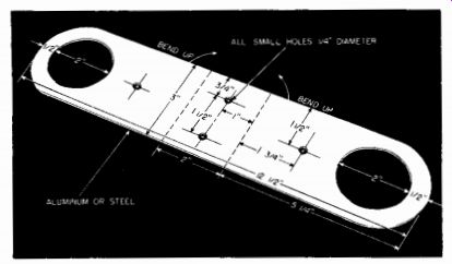
Fig. 83--Layout of the metal frame. The dimensions may be varied to suit the
size of the damp and solid rubber ball.
When the machine work and bending are finished, the base is completed by putting a 4-inch length of 1/4-inch diameter Redi-Bolt through the two opposing small holes, then fitting on a pair of flat washers and wing nuts. Do not tighten the wing nuts unless the ball is in place.
Use a solid rubber ball to make the ball joint. This is extremely important. Many of the small rubber balls offered for sale are hollow and fill with gas under pressure. Check this point before purchasing the ball.
Using a small piece of brass or steel tubing, bore a 1/4-inch hole through the ball. Sharpen the end of the tubing to give it a tapered end. Then, holding the ball in one hand and the tubing in the other, with a twisting motion force the tubing into the ball. After the tubing has cut part way into the ball, place the ball on a piece of scrap lumber or hardboard and bear down with weight to complete the boring job.
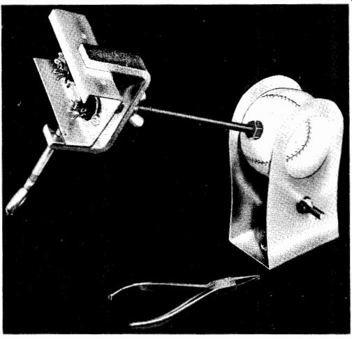
Fig. 84-Universal arm for small assemblies uses ball as movable joint.
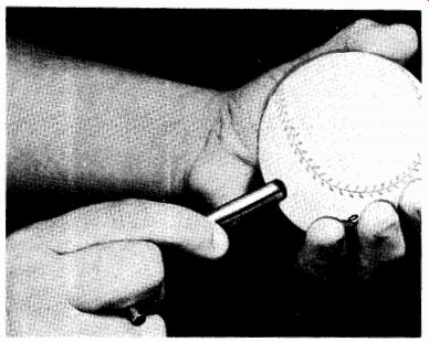
Fig. 85--To drill hole for the shaft in the rubber ball use a solid ball and "cork
borer."
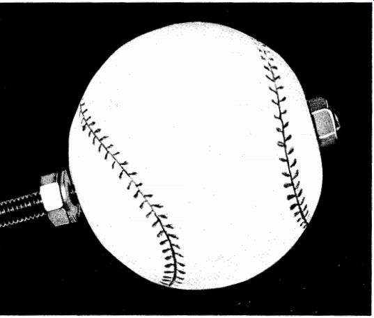
Fig. 86-Detail view of bolt mounted through the boll.
An 8-inch length of 1/4-inch Redi-Bolt, a rod stock that is available with threads already cut, serves as the support arm. Pass one end of the bolt through the hole previously bored in the rubber ball and fasten it with two flat washers and a pair of hex nuts, as shown in Fig. 86.
Tighten the nuts enough to ensure a secure mounting, but don't use so much pressure that it distorts the ball.
Next, mount a clamp at the opposite end of the support arm. Pre pare the clamp by drilling a 1/4-inch hole centered on the back strap.
Attach it to the support arm using a hex nut, flat washer, and wing nut, as shown in Fig. 87. Lock the hex nut in place with cement. This will permit the clamp to rotate freely when the wing nut is loosened, with out danger of the assembly falling apart.
Either mount the metal base permanently on the workbench or attach it to a large baseboard to be set on the bench when needed. If almost all your work is with subminiature assemblies, you will probably want a permanent mounting. On the other hand, if you work with full size chassis on occasion, the temporary mounting will be better.
With the base mounted on the support arm subassembly, complete the job by mounting the support arm assembly in the base. Loosen the wing nuts on either side and force the rubber ball between the sides of the base until it snaps into place in the large holes. Then tighten the wing nuts.
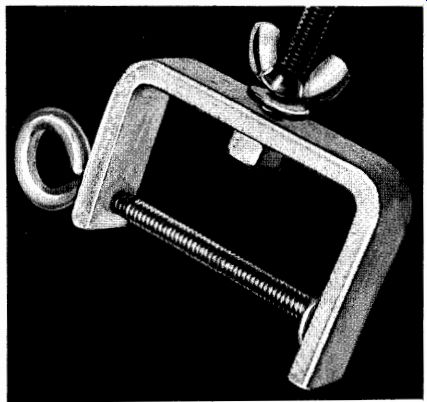
Fig. 87
The "Universal Arm" permits a miniature chassis or other small subassembly to be held in just the right position for wiring, assembling, and testing. When clamping a chassis to the arm, tighten the clamp sufficiently to ensure a snug grip, but don't overtighten. Remember that the clamp is weakened somewhat by the hole in the back strap. If you are going to clamp polished metal parts in the arm, cement felt or rubber to the interior clamping edges of the clamp to avoid scratches.
Although the "Universal Arm" is strong enough to support miniature equipment and small subassemblies, it will not support heavy weights.
Whenever the "Universal Arm" will not be used for a period of time, loosen the base wing nuts, thus allowing the rubber ball to return to its original dimensions and permitting the rubber to "rest." If the ball is kept clamped in one position for a long period of time, a permanent "set" in the rubber may result.
When working with heavier chassis, a rack such as that shown in Fig. 88 will be more suitable. It is sturdy enough to support the heaviest chassis and can be built at low cost, from readily available parts, in two or three evenings or on a weekend.
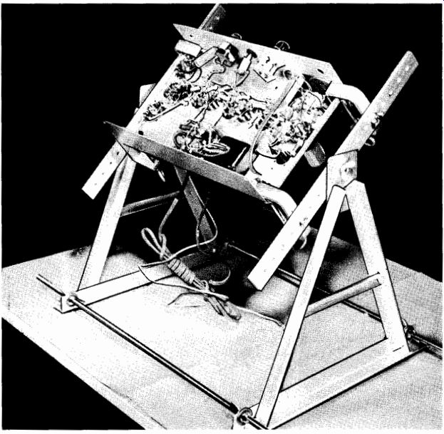
Fig. 88-Heavy-duty chassis rack is adjustable for a wide variety of chassis
sizes.
The necessary parts are specified in the parts list. With the exception of the rubber feet, most of the material should be available at the local hardware store. The aluminum used is a special soft alloy that can be worked with ordinary woodworking tools-no need for special "high-speed" drill bits or saw blades.
The chassis rack consists of three subassemblies, the "A"-shaped end frames, the "rocker arms," and the base. These can be fabricated individually, then assembled together to make the complete rack.
----------
PARTS LIST
2-14" lengths of 1" X 1" X 1/16" aluminum angle stock*
4-12" lengths of 3/4" X 34" X 1/2" aluminum angle stock*
2-14" lengths of 1/4" X 1" aluminum bar stock*
2-6 1/2" lengths of 1/4" X 1/2" aluminum "U" channel stock*
1-2" X 6" piece of "half-hard" aluminum*
2-24" lengths of 5/16" Redi-Bolt stock
8-5/16" wing nuts to fit above Redi-Bolt stock
8-Flat washers with 5/16" hole
4-Stanley "Handy Clamps" (#CD 7097K)
4-3/16" X 24 X 3/4" long stove bolts
4-3/16" X 24 wing nuts
2-1/4" X 20 X 3/4" stove bolts
2-1/4" X 20 hex nuts
2-1/4" X 20 wing nuts
2-Flat washers with 1/4" hole
12-10-32 X 3/8" machine screws with binding heads
4-Rubber feet
4-#6 X 3/4" sheet metal screws
*Marketed by the Reynolds Aluminum Company as "Do-It-Yourself" aluminum.
Two A-frames are needed. The parts required for assembling a single unit are shown in Fig. 89, and the completed A-frame is shown in Fig. 90. Cut and shape each part out of stock material, then drill all holes at the points indicated. Note that exact hole locations are not known in some cases. To locate these holes, assemble the cut-out pieces of stock material on the top of the workbench, then mark hole locations with a center punch. Perfect alignment of all parts, before final assembly, is possible when the A-frame has been loosely assembled in this fashion.
Tap the mounting holes in the side pieces for a 10-32 machine screw. When the drilling and tapping is completed, assemble each A-frame, using 3/8-inch-long 10-32 binding head machine screws-use Fig. 90 as a guide during assembly.
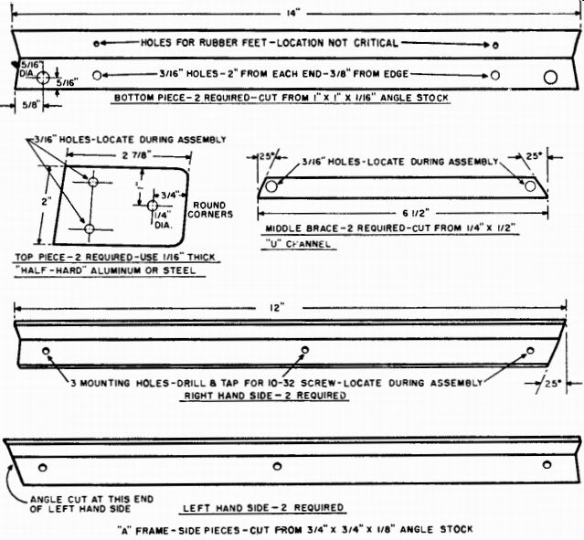
Fig. 89-Measurements of the pieces used to construct two A-frames.
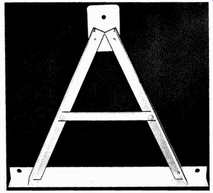
Fig. 90-Completely assembled A-frame.
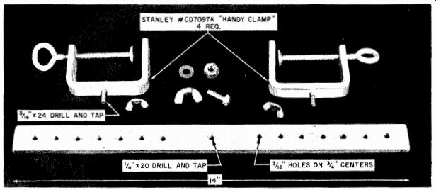
Fig. 91-Parts layout for rocker arm assembly of chassis rack.
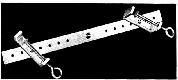
Fig. 92-Assembled rocker arm with clamps. Two of these arms are required.
The rocker arms act to support the chassis proper, and each consists of two clamps assembled on a heavy bar cut from 1/4-inch by 1-inch aluminum stock. Two bars are required. See Fig. 91 for the basic layout and necessary parts, and Fig. 92 for an assembled rocker arm.
Prepare the clamps for mounting by drilling and tapping a hole for a 3/16-inch by 24-inch stove bolt, centered on the back strap of the clamp. Insert 3/4-inch-long 3/18-inch bolts from the inside, as shown in Fig. 93. Drill and tap a hole to accommodate a 1/4-inch stove bolt in the center of the rocker arm bar and insert a 3/4-inch-long 1/4-inch bolt.
Place a 1/4-inch hex nut over this central bolt. This will hold the rocker arm away from the A-frame during final assembly.
The base consists of two 24-inch lengths of 5/18-inch Redi-Bolt, each equipped with a pair of wing nuts and flat washers at each end.
Assemble A-frames to the Redi-Bolt base piece, using wing nuts and flat washers, as shown in Fig. 94. A flat washer placed on each side of the bottom angle piece of the A-frame will increase the clamping area of the wing nuts and ensure a stronger connection. The flat washers also reduce scratches in the soft aluminum alloy as the wing nuts are tightened and released. The A-frame can be moved by loosening the wing nuts and setting them in a new position, determined by the width or length of chassis that is held in the cradle.
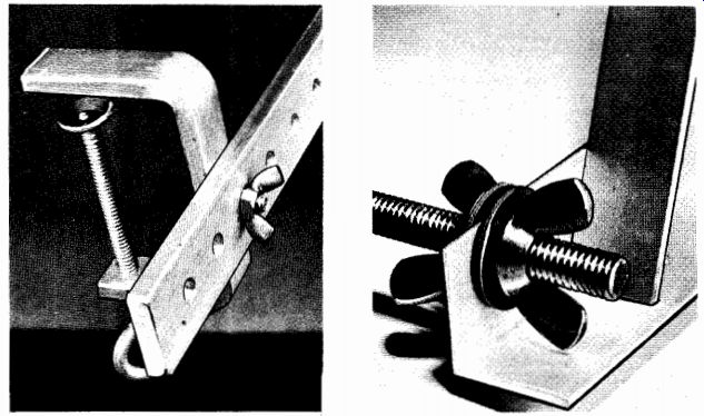
Fig. 93--Detail view of the mounting for one of the "Handy Clamps," which
are manufactured by Stanley and are available from most hard ware stores. To
compensate for varying chassis weights, the clamps may be moved along the rocker
bar to new pre-drilled positions.
Fig. 94--A-frame and base assembly.
With the clamps mounted on the rocker arm bars (use small wing nuts here), assemble the complete rocker arm to the top piece of the A-frame, employing a 1/4-inch wing nut and a flat washer. The completely assembled chassis rack is shown in Fig. 95. "Handy clamps" on the rocker arms hold the chassis, which may be swung around to permit working on either the top or the bottom. Vary the position of the A-frame on Redi-Bolts to fit different lengths and/or widths. If desired, rubber feet can be mounted on the bottom angle pieces of the A-frames, but their use is optional.
The chassis rack can be adjusted for both the width and the length of the chassis to be mounted. Adjust for width by moving the clamps to different positions along the rocker-arm bar. Adjust for length by moving the A-frames along the Redi-Bolt base. Leave one A-frame in a fixed position on the base and move the other A-frame back and forth by adjusting the base wing nuts, or move both A-frames together so that the rack remains more-or-less centered on its Redi-Bolt base. (Make sure to move both sides of each A-frame the same distance--otherwise the frame may be mounted at a slight angle, thus placing the entire rack under a strain.) Place the chassis in position between the clamps and mount it firmly by tightening these clamps. Once mounted, the chassis can be tilted to the desired working position by loosening the wing nuts holding the rocker arms to the top of the A-frame assemblies.
As shown and described, the chassis rack is designed to accommodate a wide variety of chassis sizes. For work with a chassis of a single length, the A-frames can be screwed down to a fixed wooden base plate.
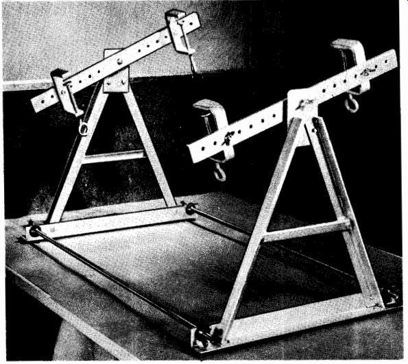
Fig. 95--Fully assembled chassis rack.
Rocker arms can be lengthened or shortened to meet individual requirements and, if preferred, the series of mounting holes can be replaced with a continuous 3/16-inch slot. The clamps specified in the parts list can be replaced with either larger or small C-clamps.
Plastic Cutter
Many electronic projects require the use of a plastic sheet material, either as a subchassis in high-voltage circuits or as a cabinet construction material for projects. Plastic sheet is also widely used in making long pointer knobs, terminal panels, and labels for controls.
Most experimenters who attempt to work with plastic sheets experience difficulty in cutting the plastic to shape. This is particularly true of thicknesses of 1/ 6 inch or less. Using a hot-wire cutter is the easiest way to form thin plastic sheets. The one described here is built from scrap wood, scrap aluminum, and very inexpensive electrical parts. It produces a fully finished edge that requires no further sanding or filing and will cut at any angle with the precision of a jigsaw.
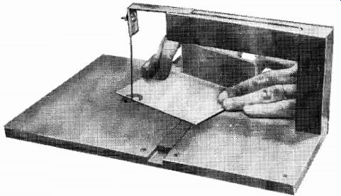
Fig. 96-How to use the completed plastic cutter to make right angles on 1/16-inch
Lucite.
The base of the cutter is formed from three pieces of 1/4-inch pine or birch plywood. The largest piece forms the lower section of the base; the two upper pieces are carefully spaced to take the slide rod of a miter guide in a tight, but smooth, sliding fit. The spacing between the two upper sections is 3/4 inch for smaller miter guides. These sections are screwed to the lower plywood layer.
Place the three base pieces in the exact position they will occupy in the finished product and mark them for the wire feed-through holes.
These holes are centered on the base with respect to the long edges and are located about 43/4 inches from one short edge. Drill the upper base layer with a 1 1/8-inch wood bit or expansion bit; this opening permits a 1-inch diameter disc of thin aluminum (with a needle-thick hole in the exact center) to fit below the surface of the top plywood board and rest on the bottom layer. Immediately below the 1 1/2-inch hole, drill a 1/4-inch hole in the lower portion of the base concentrically with the one above.
PARTS LIST
1-10" X 15" X 1/4" piece of plywood (lower base)
1--6 1/2" X 10" X 1/4" piece of plywood (upper base)
1-8 1/2" X 10" X 1/4" piece of plywood (upper base)
1--8 3/4" X 1 1/4" X 1 1/4" piece of plywood (upright)
1-7 3/4" X 1 1/4" X 1 1/4" piece of plywood (cross-arm)
4—3 1/2" X 1 1/4" X 1 1/4" piece of plywood (legs)
PL1-Pilot light assembly
S1-S.p.s.t. toggle switch
T1-Filament transformer, 117-volt step-down to 6.3 volts, 6 amperes
1-5" length of #28 Nichrome wire

Fig. 97--Disassembled view. Note position of feedthrough holes with respect
to miter guide groove.
Fig. 98--Installation of Nichrome cut ting wire.
After the base has been assembled, cut a square indentation in the center of the edge opposite the feed-through holes. This will accept a 1 1/4-inch by 1 1/4-inch upright which forms the rising member of the support arm.
A mortised and glued joint between the crossarm and upright will repay the user in sturdiness. Before assembling the cross-arm, cut a piece of 18-gage aluminum 3/4 inch wide and 4 3/4 inches long. Bend 11/4 inches of the aluminum bar down at right angles, hold the crossbar in place with the aluminum strip on top of it, and sight straight down along the bent flat. The object is to position the aluminum strip so that its short flat is directly above the wire feed-through hole. Drill the center of the short flat to clean an 8-32 machine screw before you screw the aluminum support to the crossarm.
Next, cut and glue the legs to the underside of the base at the corners and secure the crossarm to the bottom of the base by means of a 3-inch steel angle.
As a last step in the mechanical construction, mount a front apron for the cutter. Drill two 1/2-inch holes to receive the switch and the pilot light assembly; then screw the apron to the front legs.
Connect a 6.3-volt, 6-ampere filament transformer according to the diagram. Note that the pilot lamp is connected across the entire 6.3-volt secondary while only half of this winding supplies the current for heating the cutting wire.
A 4-inch length of No. 28 Nichrome wire provides the best cutting of thin polystyrene. This wire has a nominal resistance of a little over 4 ohms per foot, so that a 4-inch length draws about 4.5 amperes at 6 volts-well within the rating of the transformer. Cut a 5-inch length of the wire, knot one end, and pass the other end upward through the feed-through hole in the aluminum disc. Grasp the upper end of the wire with the tip of a pair of long-nose pliers, pass the wire around the bolt on the aluminum strip, and then tighten while holding the wire taut and the strip pulled down slightly. The strip will exert spring tension on the cutting wire and keep it from slackening.
Plug the line cord into a 117-volt a.c. outlet and turn the switch on. The Nichrome wire should become hot to the touch. The correct operating temperature is obtained when the wire is too hot to permit sustained finger contact, but not enough to show even a dull red glow.
If the temperature of the wire is too low, the cutting process will consume too much time; if it is too high, the cut sections will have an unsightly bead along the edges. Improper heating indicates incorrect wire size or dimensioning.
Plastic sheeting that is to be cut should always be scribed lightly along the cleavage line by a sharp-pointed tool. Use your miter guide to cut straight lines at any angles (curved shapes, of course, are manipulated along the scribed line free hand).
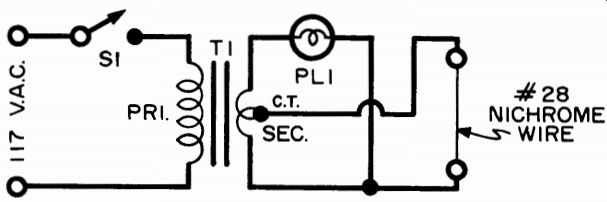
Fig. 99--Simple electrical circuit for plastic cutter heats No. 28 Nichrome
wire.
Exert very light forward pressure on the material as the hot wire passes through it. When the traversal is finished, the two cut pieces will not automatically come apart because some re-melting (called re-gelation) has occurred. Slight hand pressure on each side of the joint will always result in a clean break along the cleavage line, if reasonable care is exercised.
Coil Winder
Winding coils is often a tedious part of the experimenter's job.
When a large number of turns are required, it is difficult to get them even and close together without overlapping them. The coil winding jig shown in Fig. 100 will not only give you a professional-looking coil, but will turn out units that perform as well as factory-made coils.
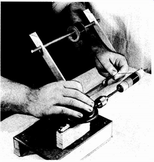
Fig. 100-Over-all view of the home-built coil-winding jig in operation. A "guide-paddle" is
used to ensure level winding and professional appearance.
The complete jig may be assembled in only a few hours. Without working too fast, you should be able to assemble the jig and wind several coils in a single evening.
The base assembly shown in Fig. 101 is made up of two pieces of 1-inch by 2-inch stock and a small rectangular piece of 1/4-inch hardboard (such as Masonite). Dimensions are not critical and you may use the measurements given in the parts list simply as a guide.
Plywood may be substituted for the hardboard.
PARTS LIST
1-Piece of hard aluminum or steel sheet (see text) measuring approximately 13" X 3"
1-Solid rubber ball about 3" in diameter.
1-REDI-BOLT, 1/4" X 20, about 12" long.
1-"Handy Clamp" made by Stanley (#CD-7097K).
3-Hex nuts, 1/4" X 20.
3-Wing nuts, 1/4" X 20.
5-Flat washers, 1/4" hale.
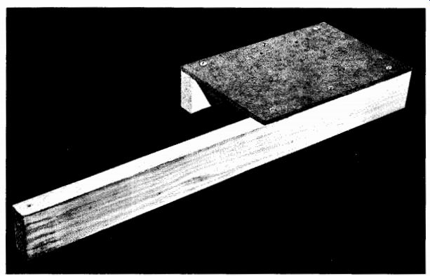
Fig. 101-Base assembly of coil winder.
Although standard round-head wood screws are used to hold the base assembly together in the model, you may prefer glue and nails, stove bolts, or other fasteners.
The illustrated model was left unfinished, but if you are handy with a brush you may wish to stain or enamel the wooden parts of the coil winder. If you do, paint the base assembly before assembling the jig.
The winding mechanism is made from an "egg-beater" type hand drill. Remove the handle and drill two mounting holes in the metal shank. On most of these small drills, the handle is simply forced into place over the shank. The handle can be removed by clamping the drill in a vise (taking care not to damage the mechanism) and driving it off with a solid punch and hammer.
Another short piece of 1-inch by 2-inch stock is used for mounting the drill mechanism in place on the base assembly (see Fig. 102).
Use long stove bolts which extend through the drill shank, the 1-inch by 2-inch block, and the hardboard. Use large flat washers under the nuts. Drive one or two wood screws from underneath through the hardboard into the 1-inch by 2-inch wooden block for additional strength.
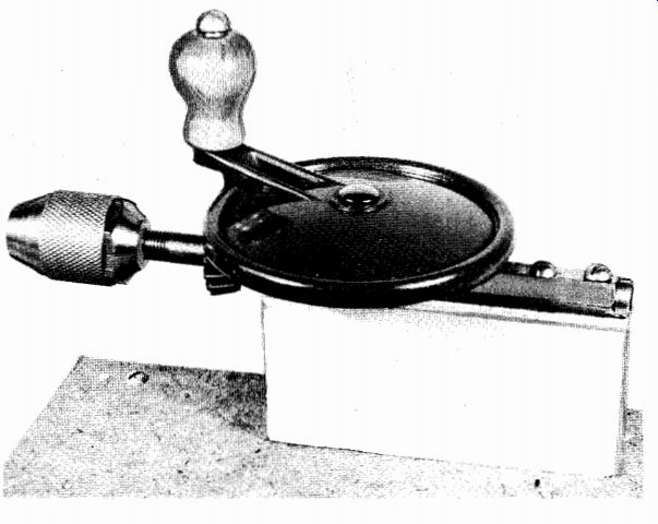
Fig. 102--Drill mechanism mounted on the base.
The wire rack is made up of two pieces of 1-inch by 1-inch extruded aluminum angle stock and a 12-inch length of 3/8-inch-diameter bar rod. The 3/s-inch rod can be aluminum, brass, steel, or plain wood doweling. Drill or punch a 3/8-inch hole near the ends of the angle stock to accept the rod. Take care to ensure a good snug fit. A strip of 1/16-inch-thick aluminum sheet is used as a "guide paddle" when winding coils, but it should not be assembled as part of the coil winder itself.
After drilling and forming the angle stock, attach these two pieces to the base assembly with small wood screws, as shown in Fig. 103.
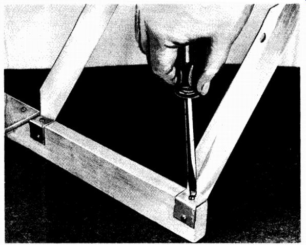
Fig. 103
The only remaining part of the coil winder is the form holder (see Fig. 104). This assembly is used to hold the coil form in place when winding coils. It is made up of a 1/4-inch-long threaded rod stock, two flat washers, a hex nut; a wing nut, and two cone-shaped wooden rods. The cone-shaped rods may be turned in a lathe from 1-inch dowel rod or whittled by hand from either dowel or a large thread spool.
After assembly, the form holder is clamped in the chuck of the drill mechanism with the hex nut nearest the drill.
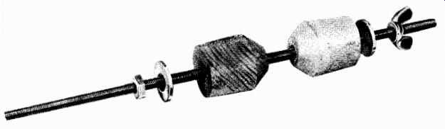
Fig. 104.
Although the coil winder is quite easy to use, proper technique is essential to achieve smooth operation and to obtain the best results.
Follow the basic steps outlined below when winding coils, until you become familiar with the operation of the jig. You can then take "shortcuts" to speed up your work.
1. Select a spool of the proper type and gage wire for the coil you wish to wind and place it on the wire rack. If you don't have the wire in a regular spool, but in a hank, wind it on an old adhesive-tape spool.
2. Drill or punch a small hole in the "guide paddle" slightly larger than the wire diameter. De-burr the edges of the hole to obtain a smooth, rounded edge which will not nick the wire.
3. Clamp the coil form on the holder between the two wooden cones. Tighten the wing nut to ensure a snug fit.
4. Thread the wire through the hole in the "guide paddle" and attach the free end at the proper point on the coil form. Use a drop of cement or a small piece of Scotch tape.
5. Hold the "guide paddle" in one hand with your thumb against the wire and rotate the drill handle with your other hand (see Fig. 100).
The guide paddle serves two purposes. First, with your thumb in place over the wire you can vary tension as necessary to ensure a smooth, tight winding. Second, you can guide the wire along the form to obtain either a close- or a wide-spaced winding.
6. When the coil is completed, keep tension on the wire (using the guide paddle) until you can fasten the end of the coil. Again, you may use a drop of cement or a piece of Scotch tape.
Any one of several methods may be used to keep track of the number of turns placed on the coil. If the coil is to have fifty turns or less, you can simply keep a mental record as you wind the coil.
Another method is to determine the number of turns of the coil form holder obtained with one full rotation of the drill mechanism handle, and then to rotate the drill handle enough times to give the coil desired. In the model, a single rotation of the drill handle gives three and one-third revolutions of the coil form, thus a 110-turn coil may be obtained by rotating the handle thirty-three times.
Still another method is to refer to the wire-size table and to determine the number of turns per linear inch obtained with the type and size wire you are using. The coil form is then marked off to indicate the length of winding, and wire is wound on the form until the marked space is completely filled. For example, No. 26 wire (B. & S. gage) with enamel insulation gives approximately fifty-eight turns per inch. A winding 2 inches long would contain 116 turns. This method is best used with close-spaced coils, but may be used, in modified form, where the spacing is equal to multiples of the diameter of the wire.
Permanent Breadboard
The experimenter who enjoys working with new circuits or likes to do his own development work will find that a permanent "bread board" chassis will make his job easier. He can quickly set up and modify almost any circuit he desires with this chassis.
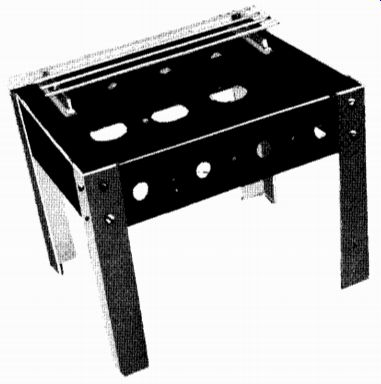
Fig. 105-The versatile "breadboard" chassis.
The chassis itself is drilled and punched from a standard 7-inch by 9-inch by 2-inch chassis base which is available from most parts distributors. The drilling layout for the top of the chassis and end and side layouts are shown in Fig. 106. Both ends and both sides are identical. Drill the small holes and use Greenlee or Pioneer punches for making the large holes.
Four leg brackets are needed. These are made from 1-inch by 1-inch by 1/6-inch thick extruded aluminum angle.
Socket holes in the main chassis are for standard octal sockets.
If you work with miniature tubes, you will need adaptor plates for 7-pin and 9-pin miniature sockets. Dimensions for these adaptors are included in the mechanical diagram. Make as many as you think you'll need.
Any number of small accessory brackets can be made, depending on your individual requirements. Typical dimensions for a volume control bracket are given. You may wish to make brackets either larger or smaller or to make special brackets for particular jobs.
Mount the four leg brackets on the chassis, using 3/5-inch No. 6 sheet metal screws. Mount the two terminal strips and four ground lugs with similar screws. Run four or more straight pieces of No. 12 tinned bus bar between corresponding positions on the terminal strips, soldering at both ends. When finished, the completed breadboard chassis should look like the one shown in Fig. 105.
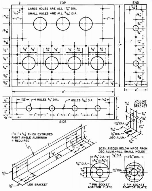
Fig. 106-Plans for assembly of permanent breadboard.
PARTS LIST
3 ft. 1" X 2" stock lumber 1 pc. 3/4" Masonite or 3/8" plywood, 6" X 9" 1 Egg-beater type hand drill 2 ft. 1" X 1" extruded aluminum angle stock 1 ft. 3/8" dia. bar stock (see text)
Misc.-screws, 1/8" threaded rod stock, wing nut, hex nut, flat washers, 1" dowel rod, etc.
When you are ready to wire an experimental circuit, mount all tube sockets, brackets, and special terminal strips on the breadboard chassis with No. 6 sheet metal screws.
If the adaptor plates are to be used, mount the miniature tube sockets in them using 1/4-inch 4-40 machine screws and small hex nuts.
Mount the adaptor plates, in turn, on the chassis proper, using longer sheet metal screws and 1/4-inch stand-off spacers. They are mounted over the large tube socket holes.
All tube sockets are mounted so that the tubes plug in below the chassis. This permits all wiring to be kept above the chassis and exposed and makes it easy to do tests and experimental circuit changes.
Lap joints are used for all wiring, with ground, "B plus," and filament connections made through the bus bars.
In addition to simplifying the original assembly and wiring job of an experimental circuit, the use of a breadboard also makes the disassembly job easier. The exposed wiring and lap joints permit the experimenter to tear down a circuit in "jig" time.
Jig for Soldering-gun Tips
An inexpensive way to keep your soldering gun in top operating condition is to have a stock of spare tips on hand. Soldering-gun tips soften and corrode with use and should be replaced when this occurs.
To keep your shop well stocked with tips, the jig layout shown in Fig. 107 will help you turn out new tips as you need them, at small cost, and with only a few minutes work. It can be made from a few scraps of wood and a small strip of 18-gage aluminum. The stock for making the tips is a roll of No. 10 soft-drawn copper wire. As each tip you make will require only a little over 7 inches of wire, one roll will last a long time.
To make the jig, cut the rectangular base (A) from hard wood, such as maple or oak. Prepare the forming block (B) by cutting it to size and then beveling it at an angle of 45°. Hacksaw and file an aluminum strip (C) to size. Drill and countersink it for 1/2-inch No. 6 flat head wood screws. Secure the strip (C) to the side of the forming block (B), as shown in the illustrations, using wood screws. Let the strip project downward toward the base a distance of about 1/16 inch beyond the bottom of the forming block when you do this. The projection will fit into a groove chiseled into the base to prevent the strip from bending while the tip is being made. The right end of the strip projects exactly 1 3/8 inches beyond the end of the beveled forming block. After you have chiseled out a recess for the bottom edge of the aluminum strip, screw the forming block to the base. By sinking the strip in the base this way, a degree of rigidity is obtained that is of great help in using the jig.
As a final step, screw two round-head wood screws into the base near the aluminum strip. (Be sure to separate the screws from the strip by the diameter of the No. 10 wire to be used.) These holding screws (D) arc allowed to protrude above the base about 1/4-inch.
To use the jig, first cut a length of wire exactly 7 1/4 inches long.
Slide the end of the wire between the strip and the holding screws to the starting line (E), and bend the wire around the end of the strip.
Using a pair of gas pliers or long-nose pliers, squeeze the wire around the bend close to the strip on each side and then continue to bend it by hand so that it follows the contours of the forming block.
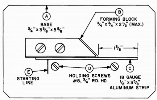
Fig. 107--Job layout. Letters refer to parts as explained in text.
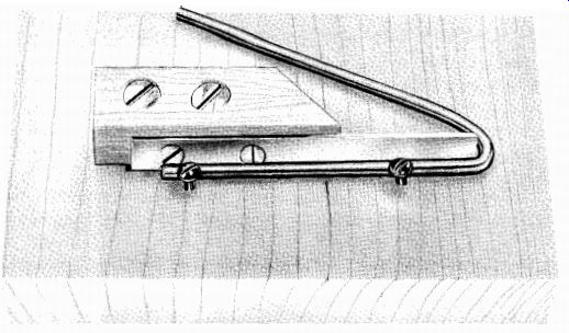
Fig. 108--Second step in making a tip for the soldering gun is to bend the
7 1/4-inch strip of wire back over the metal forming piece.
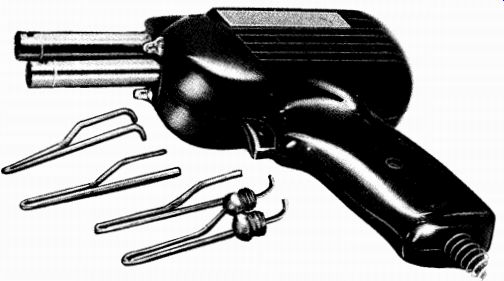
Fig. 109--Soldering gun with new tips ready for assembly. End of tips that
fit into gun barrels must be bent slightly after the clamping nuts are attached.
Place the clamping nuts (supplied with the gun) on the wire.
Make certain that the threads face the right way to permit fastening to the gun. Then bend 1/4 inch of each end of the top; insert into the gun's retaining holes; and tighten the clamping nuts. The new solder tip is now correctly mounted. Tin the tip, and the gun is ready for use.
Another useful accessory for the electronic workshop is a d.c. power supply that can be used to drive small motors, such as those used in hand-carving tools. The d.c. supply will give you a higher motor speed without excessive heating of the motor.
Construct the base and uprights from 3/4-inch wood stock and drill a 1/4-inch hole in each of the upright pieces to pass the electric cord and wiring. Then mount and wire the socket (S01), capacitor (C1 ), and rectifier (SR1) as shown in the diagrams.
Cut a protective shield from hardware cloth or wire screen, then bend and fasten it with wood screws and washers. As an added safety measure, tape the exposed socket connections.
The d.c. supply must be used with motors drawing less than 0.5 ampere; those drawing more current will burn out the rectifier. It can only be employed with motors using d.c. or a.c./d.c.; motors using only a.c. will not work on the d.c. output of the rectifier.