Hum bars and small pictures are not the only symptoms of open filter capacitors. Filters that bypass the common voltage supply of several basic circuits can allow (if they become open) a mixing of these signals. The unusual symptoms that are produced can be eliminated by following the tests described here.
By Homer L. Davidson
Conventional or unusual symptoms
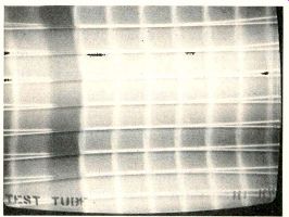
Figure 1---Three classic symptoms of an open power-supply filter are two
rounded black horizontal bars in the picture, horizontal displacement
at the bars and a smaller picture size. With crosshatch, the bars are
stationary; while on station signal they move slowly up through the picture.
Symptoms of defective filter capacitors range from the usual hum bars and audible hum to others that seem to have no connection with power-supply problems.
In previous years, most technicians tested for bad filters by paralleling the suspected capacitor with a new one of the correct value.
Of course, this test cannot identify leaky capacitors. Another limitation is the temporary healing of some capacitors because of the severe voltage surges produced by shunting while the power is on. Despite these restrictions, the paralleling test generally was satisfactory in previous years. But components have changed to types having less tolerance for overloads, so modifications of the test are necessary.
One good method is to turn off the power before a test capacitor is connected to the circuit. Following the test, the power should be turned off before the capacitor is disconnected. An elegant solution is to use one of the capacitor-substitution boxes that permit charging the capacitor before it is switched in direct.
Unusual symptoms--One old-timer in the TV-servicing field once said, "I always shunt the filter capacitors in the low-voltage supply when unusual symptoms appear on the screen. I find that it solves about 60% of my service problems." Dangers to solid-state components from voltage surges have been mentioned already, and precautions must be taken. However, the old timer's reasons for using this test to locate those hard-to-explain symptoms remain valid for modern equipment.
Many different sections of each TV obtain dc power from the same source. When a capacitor opens, the signal impedance of that supply no longer is near zero. Waveforms of hum, audio, vertical or horizontal signals appear on the B+ lines and are brought into other sections.
Therefore, the symptoms of a defect appear in a section that does not have a problem except from the signals fed through the power supply.
Analyze waveforms--A better test method than shunting is to scope the waveforms at the various branches of the B+ supply. This is particularly valuable where the B+ circuit is not readily accessible but the signal wiring can be reached easily.
In most cases, no detailed analysis is needed. If the schematic calls for about 1 VPP of 120-Hz ripple, but horizontal pulses of 100 VPP are there, don't analyze the pulses but eliminate them by finding the bad capacitor. When a new capacitor has removed the hash and pulses, the original problem probably will be gone also.
Notice, however, that the excessive amplitude of a wrong wave shape has located the supply line which is not properly filtered.
Test equipment---No unusual test equipment is required to find which filter is defective. Most good shops have everything that's needed.
These items of test equipment are recommended:
a meter for measuring dc and ac voltages plus resistances (many problems reduce the B+ voltage);
a scope calibrated to read peak-to-peak ac voltages (it can show foreign waveforms and the total amplitude); and
a generator of crosshatch patterns (better for showing bending).
In addition, a capacitor substitution box covering the larger values needed for solid-state merchandise is an excellent time-saver. A model that reduces surges is highly recommended.
Another optional instrument for solving difficult cases of borderline performance is a capacitance meter. Some new models have a direct-reading digital display.
Typical symptoms
Dark horizontal hum bars that move slowly up through a narrow picture (Figure 1) are one classic symptom of bad filter capacitors.
(Of course, bad tubes can cause the same hum bars in sets that have tubes.) These dark bars sometimes are accompanied by bending of vertical lines as the hum moves up the screen. Audible hum might or might not be heard in the speaker.
Incidentally, an erratic bending of vertical lines (but without hum bars) can be caused by high power factor in the filter that bypasses the supply to the horizontal-sweep circuit.
However, many other symptoms (some very unusual) can be produced by filter capacitor defects in some TV models. Some of these are explained in the case histories that follow.
Previous repair
The complaint against an old Sears color receiver was a kink in the picture that travelled upward. Obviously, the flyback transformer and two filter capacitors had been replaced by another shop. In fact, the cans had not been replaced, but instead the two separate capacitors were hanging by their leads under the old ones (see Figure 2).
Both capacitors checked above the rated values and the dc voltage at the output of the power supply was about correct. However, the scope indicated excessive ripple at the second filter capacitor (the one downstream from the filter choke). Shunting another 100 uF capacitor across it made little difference.
When measuring the dc voltage at each side of the choke, there was only slightly more than 1V difference between the readings. Since the drop should have been higher, the choke winding was checked and found to be less than 1-ohm. Insulation paper around the winding was brown from excessive heat.
The original C2 probably had shorted or become leaky, damaging the choke. And the shorted turns reduced the filtering, causing hum in the picture.
Quite often, one shorted section of a multiple can is followed soon by failure of another section. There fore, the choke and all complete filter cans were replaced at the same time, solving the hum problem.
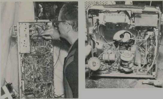
----------The author checks filter capacitor voltages in an older color
TV.
-----------The method of finding open capacitors by scoping the B + supplies is especially helpful when the filters are not accessible.
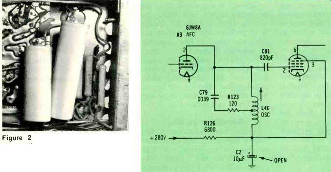
Figure
2 Paralleling new capacitors across the old ones if not recommended. Failure
of a second section often follows the original failure. These capacitors are
too near the hot resistors, and their size further restricts the air flow.

Figure 3 An unstable horizontal oscillator was caused by an open in
C2.
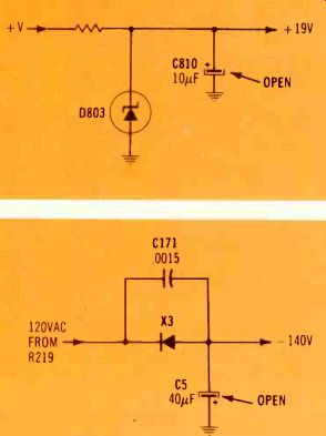
Figure 4---Picture pulling (and no other symptoms) resulted from an open
C810. Zener D803 regulated the dc voltage, but did not eliminate enough
of the ripple.

Figure 5---Lower voltage and higher ripple because of an open filter
capacitor can cause both increased brightness and video hum, when the
supply furnishes negative voltage to the brightness control.
Poor horizontal locking
The picture on this Olympic CTC31-chassis television would lose horizontal locking when channels were changed or during a videotape problem. In addition, the horizontal locking was very loose.
All dc voltage measurements, resistance tests and waveforms showed nothing wrong in the AFPC and horizontal-oscillator stages.
However, when a similar value was paralleled across C2 (Figure 3), the locking was normal. Replacement of C2 produced solid locking.
Picture pulling Picture pulling was the problem of a M25-chassis Admiral. Some sideways movement of certain picture elements was minimized by careful adjustment of the horizontal-oscillator coil. But this border, line adjustment brought on an intermittent loss of horizontal locking. It was clear that defective components were to blame and not adjustments.
A new horizontal module was installed, but without any improvement. Occasionally, a new module will be defective, so a second module was tried. Again, there was no change.
Voltages in the horizontal circuit were within tolerance. A scope check of the +19-V supply indicated excessive ripple. Module M800 was not in stock, so capacitor C810 (see Figure 4) was shunted with a test capacitor. Both the pulling and the ripple were reduced. After C810 was replaced, performance was normal. The zener diode (D803) regulated the dc voltage but did not eliminate all of the ripple.
Excessive brightness
When brought to the shop, a Penncrest model 4828 had 60-Hz hum in the picture and excessive brightness that could not be reduced enough by the brightness control.
At first, it was believed that two defects (one video and one filter) were causing those symptoms. How ever, scoping the +260 V supply and shunting its capacitors gave no improvement.
Brightness problems often originate in the video stages, and hum sometimes does too. During a search of the schematic, it was noticed that -140 V was applied to one end of the brightness control through a limiting resistor.
Only -17 V was measured at the brightness control, with about-70 V at the anode of diode X3. Checks of all parts around X3 showed the diode was okay, but filter capacitor C5 was open (Figure 5).
The open CS reduced the negative voltage (increasing the brightness) and also introduced 60-hz hum into the video via the brightness control. A new capacitor solved both problems.
Something burning
Smoke from underneath the chassis indicated some component was too hot in the RCA CTC31 chassis. After the chassis was placed on the bench and connected to a test jig, R226 (see picture in Figure 6) was found to be extremely hot. R226 is a small 680- f2 decoupling resistor in the +350-V supply (Figure 7), so it seemed certain that some kind of short or overload in this supply was causing excessive current.
All wires and the resistor lead were removed from the lug of C3A.
The capacitor was checked for leakage, but the leakage was nor mal. Neither were any shorts discovered at any of the other leads that had been connected to the lug.
A new resistor was installed and all wires reconnected to the capacitor lug. When the power was turned on, the new resistor began to heat excessively and smoke.
After several frustrating hours of hunting for a short circuit, a broken terminal lug at C2A was found which gave the effect of an open capacitor. At first, it seemed impossible for this capacitor to cause heating in the other branch of the supply. However, the installation of a new resistor and a new C2A capacitor restored correct operation.
By now, there could be no doubt; an open C2A had been the culprit.
Further study of the schematic revealed the reason. C2A bypasses the horizontal pulses that back up from the sweep. When C2A was open, the other filter (C3A) tried to bypass those pulses. However, the current from the filtering of the pulses had to pass through R226.
So, the unusual current of C3A was causing R226 to burn up.
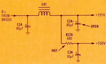
Figure 7 When C2A is open, R226 runs too hot and often fails. Without
the capacitance of C2A, excessive amplitudes of horizontal pulses and
ripple are produced there. However, C3A is a low-impedance path for such
signals and it is separated from C2A only by R226 which has a low resistance.
The full amplitude of pulses and ripple therefore is placed across R226.
This strong capacitor current is sufficient to ruin R226.
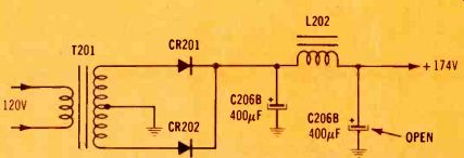
Figure 8 Frying noises and unstable double-triggering raster lines were
the symptoms when the SCR horizontal-sweep filter (C2068) was open.
Arcing sounds
When the Zenith model B4030W was turned on and the tubes heated enough to operate, a loud arcing sound could be heard. The sound was similar to arcing in the tripler, but the flyback was buzzing and the whistle from the sweep circuit was heard at too low a frequency.
In addition, the horizontal-output tube was running a red plate.
Replacement of the oscillator and output tubes eliminated the over heating of the output tube. But the raster showed white erratic lines and the stripes of wrong horizontal frequency. Adjustments of the horizontal oscillator helped very little.
Scoping the +270-V source revealed excessive hash and horizontal pulses at C1B. And the source measured only about +190 V.
Shunting another capacitor across C1B restored the horizontal locking and stopped the arcing noises. For a permanent repair, the whole C1 can was replaced.
Frying sounds
Frying noises in the speaker and erratic arcing lines in the raster along with a height of about 5 ins were the symptoms of the RCA CTC74 color TV.
Rotation of the horizontal-hold control either made the condition worse or caused the breaker to trip.
Varying the brightness made no change. Squeals could be heard from the flyback transformer.
This receiver had been brought in from another shop. Many of the diodes, small capacitors, both SCRs and other components had been replaced. In fact, about the only part not replaced was the flyback.
First, the horizontal module was replaced, but that cured only the horizontal squeal. There was a tip in the tech-note file about this model, and a visual examination showed a loose terminal inside C206B (see Figure 8). C206B is the main bypass of the supply to the horizontal-output stages. A new one solved the problem.
If the tech-note had not been handy, the bad capacitor could have been located by scoping the +174-V supply and finding horizontal pulses.
Seasick picture
Watching the wavering picture on this 3M20 Admiral could have made a viewer seasick. At times it resembled the commercial of the man who ate too much, except that hum bars could be seen also.
All filters were scoped immediately, but no unusual waveforms were found. To make sure the power supply was not the source, each filter was shunted in turn (with the power turned off during each connection or disconnection). Again, no discrepancies were found.
A study of the schematic revealed that the +25.8-V source supplies the IFs, video, color stages and the video output. The scope showed more ripple and hash than should be present at that point.
However, that same supply had been shunted without the trouble being cured. Noticing the 4000 uF value of C103A in Figure 9, brought to mind that the test capacitor had been one of 100 uF.
Of course, this size is much too small for that circuit.
When a 4000 uF capacitor was connected temporarily, the queazy picture quieted to the usual stability, and the previous ripple-plus-hash waveform (Figure 10) changed to a straight line.
A new C103 metal-can capacitor completed the repair.
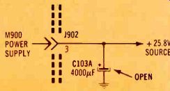
Figure 9 An open C103A caused extreme picture pulling. A test capacitor
of lower value will not remove the symptoms.
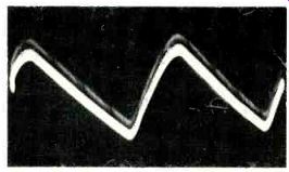
Figure 10 This is the waveform at C103A (see Figure 9) when it was open.
After a new one was installed, the waveform was a straight line.
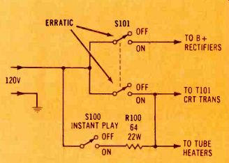
Figure
11 When an intermittent switch interrupted the 120 volts at the common
lug of S101, the power evidently traveled through R100 and supplied both
the CRT transformers and the B+ rectifiers with reduced voltage. However,
the symptoms were similar to those of bad filters: hum bars and a narrow
picture.
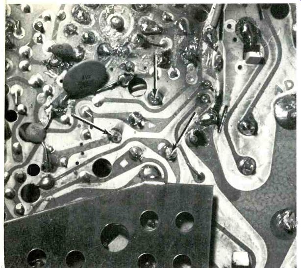
Figure 12 Arrows point to the ground lugs of the 2-section filter capacitor.
Normally, the ground circuit is completed through these lugs and the metal case of the capacitor. When a misguided technician installed two separate capacitors, the ground circuit was opened and the TV was dead. Watch for this in other receivers.
Bad filters?
The model 6A1-1762A Montgomery Ward TV receiver had a narrow picture with hum bars in it. These are common symptoms of an open filter.
However, when the main on/off switch was left in the on position, the vacation switch could turn on and off all the power. These symptoms were intermittent.
Then it was noted that the CRT heater voltage was only about 4 V, and all other tube heaters were abnormally dim. In addition, the B+ measured only +210 V. All of these symptoms indicated a low line voltage, but no reason could be seen.
When the on/off switch was bumped accidentally, the picture became full sized, the tubes were brightly lit and there was no hum.
Apparently, an open was occurring between the line voltage and the common side of 5101 (Figure 11).
With this open circuit, both heater voltages and the ac for the rectifiers were supplied through R100, which dropped the voltage and upset the peak-reading action of the filter system.
This freakish defect gave all the usual symptoms of open filters, and the case should serve as a warning to not replace filters before other tests prove them to be defective.
Two equals one? After it was opened in the shop, the monochrome 6H4-1A Admiral was found to have two tubular filter capacitors mounted on top of the circuit board to replace a two-section can. These capacitors were of the correct ratings and were soldered into holes used by the original can.
There was one mistake. Part of the original wiring had entered at one common lug of the can and had left by way of another lug of the can. The technician who in stalled the two separate replacements had not connected these two points together. Therefore, the ground circuit was open. Installation of the correct 2-section can capacitor brought the TV to life (Figure 12).
Comments
When filter capacitors open, several distinctive symptoms are produced. And the exact symptom often indicates which capacitor is open.
An open first filter capacitor (the one nearest the rectifier) reduces the supply voltage and greatly increases the ripple.
An open second filter capacitor (the one after the choke) has little effect on the supply voltage. It might increase the sound or picture hum slightly. But it's more likely to cause some weird symptom. Picture pulling or double triggering of the horizontal are two common problems.
Shorts or leakage between sections of capacitors that are in the same multiple-section case are rare (fortunately). They are difficult to find, since the usual paralleling or shunting will not be an effective test.
Open filters beyond the two mentioned first usually do not add hum to either picture or sound.
And the symptoms can seem to indicate defects in almost any other section of a receiver. Scoping or shunting are recommended to find open capacitors in those cases.
-----------
Also see: Selecting replacement capacitors