AMAZON multi-meters discounts AMAZON oscilloscope discounts
25. Potential and Potential Difference
As mentioned in Section 14, the potential difference between two points may be defined as the ratio of energy to charge, or:
Potential Difference = Energy /charge (38)
It remains to determine the units that may be properly applied to this relation and to visualize the physical meaning that underlies the concept of potential difference.
The absolute potential of a given body is measured by the number of ergs or joules required to bring a unit charge q of like sign (so that work must be done against the repelling force) up to the body from infinity. Absolute potential is virtually impossible to determine, but for convenience the earth is assumed to be at zero potential and all other potentials are measured relative to it.
It may be shown by the integral calculus that the work done in moving any point charge q from infinity to a distance r from another point charge q (in the mks system) is given by the equation
W = qq' / 4 pi e_0 r joules (39)
The equivalence of work and energy makes it possible to state that the work done according to this equation is also the potential energy given to the point charge as a result of moving it from infinity to a distance r from another point charge of similar sign. Since electrical potential is the ratio of energy to charge,

(40)
(41)
According to the definition of the volt given in Section 2, however, it is fundamentally the same unit as the joule per coulomb, hence the expression above is said to be the potential in volts of a point charge q with reference to some zero level taken at a great distance away from the point charge.
Determination of the potential around a charged conducting sphere will demonstrate several interesting points. We have already shown that the electric field around a charged sphere may be computed by considering that the entire charge is concentrated at the center of the sphere. The potential of such a sphere is, therefore, also given by Equation 41, in which r must be taken equal to or greater than the radius of the sphere.
Now consider such a sphere being charged in air by some electrostatic method. (Such methods will be discussed in Chap. 5.) When the electric field intensity becomes sufficiently great, the air in the vicinity of the sphere becomes conductive and the charge leaks off as fast as it is generated. The question arises as to what factor or factors determine the maximum potential to which the sphere can be charged. This question may be answered by reasoning as follows: designating the maximum electric field intensity by Em.., we can determine the largest charge that the sphere can hold by solving Equation 19 for q:
(42)
in which r. is the radius of the sphere. Substituting this value of q_max into Equation 41,
(43)
Experimental evidence shows that air becomes conducting when the field intensity approaches 3 X 10^6 volts per meter, hence the maximum potential in volts (the voltage) that can be built up on a con-ducting sphere of given radius regardless of the charging method is:
Vmax = 3 X 10^6 (r) volts (44)
…where r. is measured in meters. This development provides a supplementary explanation of the phenomenon of discharge from points discussed in Chap. 3. Since the maximum voltage is a function of the radius of the charged body, a surface that has an extremely small radius of curvature cannot sustain a high potential without causing ionization of the air and consequent discharge. In addition to this, it also illustrates the reason for the use of extremely large spheres in million-volt Van <le Graaff generators.
Example:
What is the maximum potential to which a "point" having a radius of 0.01 mm can be raised? Solution: Vm,. = 3 X 10^6 X 10^-5 = 30 volts
Example: A Van de Graaff generator has a sphere of approximately 2-meter radius. What is the maximum potential to which it can be charged? Solution: Vmax = 3 X 10exp6 X 2 = 6,000,000 volts.
Physicists, using the mks system, measure field strength in new tons per coulomb, rather than in volts per meter. These units are, however, exactly equivalent. A volt is defined as a joule/coulomb, but a joule is a newton-meter.
Substituting these units in Equation 19, joules
Field strength = E = volts coulomb
= meter meter
The distance unit cancels leaving E = newtons/coulomb
newton-meters coulomb meter
(45)
26. Equipotential Surfaces
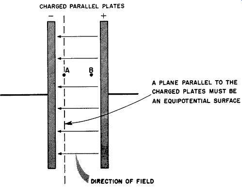
fig. 20. Study of an equipotential surface.
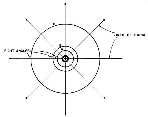
fig. 21. The electric field around a charged sphere passing through equipotential
surfaces.
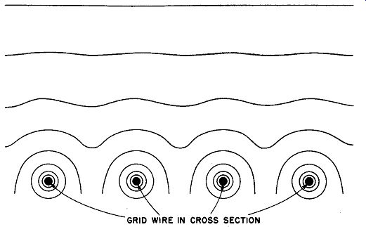
fig. 22. Equipotential surfaces around the grid of a vacuum tube.
If two points between charged plates, such as A and B in Fig. 20, are given a difference of potential, work is required to move a charge up the potential from A to B. If the charge is moved parallel to the plates, however, work is not required because the motion is occurring in a direction in which there is no component of field force due to the electric field. If there is no resisting force component, work is not necessary to maintain uniform motion. For this reason, all points in a plane passing through point A and parallel to the plates have the same potential as point A. This follows from the fact that there can be a potential difference only if work is required to move the charge.
A surface on which all points have the same potential is called an equipotential surface.
This concept has several important implications. The surface of any conductor with a static charge must be an equipotential surface.
If a potential difference existed for an instant between points on the conducting surface, there would be an immediate movement of charge from the points of high potential to those of low potential and this movement would continue as long as the potential difference existed. As we shall see later, the plates of a capacitor, irrespective of their shape or position, must also be equipotential surfaces.
A second important idea is that electrostatic lines of force must pass through equipotential surfaces at right angles. 1 e_ this were not the case, components of the field along the surface would exist, and movement of charges would take place. A difference of potential would thus exist along the surface, contrary to the definition. As may be observed, this is true of the equipotential surface in Fig. 14.
Again, consider a charged sphere like that of Fig. 21. The charged sphere is the innermost circle bearing the plus sign. Since the field of the sphere is radial in nature, each force line must pass through con-centric spheres of larger diameter perpendicularly. Hence, surfaces A, B, and C are equipotential surfaces. It should be noted that a similar condition exists for coaxial cylinders.
With more general distribution of electric field sources, equi potential surfaces take on more diversified shapes. Such surfaces, as they might appear around the control grid of a vacuum tube, are shown in Fig. 22.
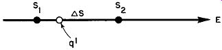
Fig. 23. The force acting an a test charge due to an electric field.
In drawing a series of equipotential surfaces, it is conventional to indicate them as surfaces having uniform voltage increments. (Each surface is shown separated from the adjacent one by an equal potential difference.) When this is done, the surfaces are increasingly further apart, as the distance from a single charged source increases. This is due to the greater divergence of the radial lines from a central charged body as the distance grows.
27. Potential Gradient
An important term often encountered in electrostatics is potential gradient. To study its significance, consider the force acting on a test charge q' in an electric field of intensity E, as shown in Fig. 23.
Electric field intensity is given by the equation E = F/q', hence the force acting on the test charge q' is equal to Eq'. This force acts upon the test charge to move it from S1 to S2, that is, over the distance delta_s, which we shall take as being infinitesimally small. In order to stop the motion of the test charge, or to move it slowly in the opposite direction without acceleration, the force required would be -F. For this case, then,
-F = Eq' or F = -Eq' (46)
in which F is the force required to move q' in the direction S2 to S1. If such a force is applied to the test charge and succeeds in moving it from S2 to S1 (a distance delta_s), the work done is
W = F delta_s = -Eq delta_s (47)
The work done in moving the test charge against the electric field represents an increase in potential energy. Thus, the increment of electric potential, AV, is the increase of potential energy per unit charge or:
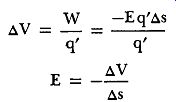
(48), (49)
The ratio delta_V/delta_s is the rate of change of potential with distance in the direction of the electric field. The minus sign before the ratio indicates that the electric intensity is the negative of the potential gradient, in the direction of the electric field. Potential gradients are expressed in volts per meter or microvolts per meter in the mks system.
Let us summarize the characteristics and properties of equipotential surfaces as follows:
1. Equipotential surfaces never intersect in a finite field.
2. It is always possible to draw a series of lines indicating the direction of the field strength perpendicular to these surfaces.
3. The field is stronger where the surfaces are closer to each other.
4. The field strength is the negative of the potential gradient.
5. When two bodies bearing charges of opposite sign--such as a pair of charged plates--produce a field between them, this field may be quite uniform throughout the space separating them.
In such arrangements, the equipotential surfaces are equally far apart.
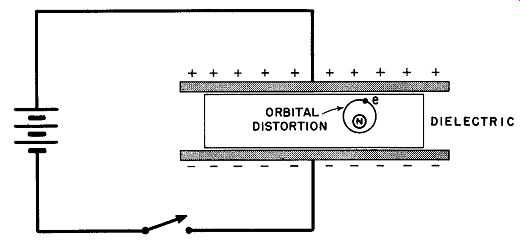
Fig. 24. How energy is stored in the dielectric of a capacitor.
28. Capacitance
When two conductors that are separated by an insulator are connected across a source of potential, as shown in Fig. 24, the plates become oppositely charged. When the activating potential is removed, the charge remains on the plates for as long a period as leak age through the insulating material or dielectric permit. This residual charge constitutes stored electricity, while the property of storage in an electric circuit is known as capacitance. In the elementary explanation of the storage ability of a capacitor (a device that exhibits capacitance), it is often erroneously stated that the energy of the stored charge resides in the plates of the capacitor, since it is easy to discuss the charges thereon as bound charges. The mutual attraction of opposite charges superficially appears to offer a satisfactory answer to the question as to the mechanism of energy storage.
That this is not a fact is demonstrated when the dielectric material is changed. For example, a given capacitor is capable of storing a certain amount of energy when air is used as the dielectric; if glass is now substituted for the air without changing the voltage of the charging source, the storage ability of the same capacitor rises by a factor of at least five. Since neither the area nor separation of the plates has changed, this increase in energy content signifies that storage of energy occurs elsewhere. It is generally agreed that the energy of a capacitor resides in the dielectric rather than on the plates. The actual mechanism by which this is accomplished is not perfectly understood, but it seems quite certain the orbits of electrons circling the nuclei of the atoms of the dielectric are distorted by the electrostatic field between the plates. Any change in the normal shape or dimension of such orbits must represent potential energy similar to that of a stretched rubber band or a compressed spring.
As the voltage applied to a capacitor is increased, the charge increases in direct proportion. That is:
Q~V (50)
... where Q is charge magnitude and V is applied voltage. This proportionality is converted to an equation by multiplying the right side by a constant of proportionality that we designate C, the capacitance of the capacitor (by definition).
Q = CV (51)
where Q may be measured in coulombs and V may be measured in volts. Solving for C we have:
C = _R V (52)
The fundamental unit of capacitance is the farad (named for Michael Faraday, 1791-1867). One farad is the equivalent of one coulomb/volt and is defined as that capacitance which will accept a charge of one coulomb when the applied voltage is one volt.
The farad is a prohibitively large unit for practical use. In equipment where capacitors are used, it is common to encounter ratings in terms of microfarads (1 µ.f = 10^-6 farad) and micro-micro farads (1 µ.µ.f = 10^-12 farad).
An additional relationship that finds much application may be obtained by utilizing the fact that the one ampere of current flow is defined as one coulomb per second.
Hence: I_t= CV (53)
... where I is current in amperes, t is time in seconds, C is capacitance in farads, and V is voltage in volts.
Example: A 100 µf capacitor is connected across a 300-volt d-c line. (a) Find its charge in coulombs when fully charged and (b) calculate how long it must be allowed to charge to reach full charge if the average current flowing into it is 0.1 ampere.
Solution:
(a) Q = CV
Q = 100 X 10^-6 X 300 = 3 X 10^-2 = 0.03 coulomb CV
(b) t = -
I = 100 X 10^-6 X 300/0.1 = .03/0.1 = 0.3 second
29. The Energy Stored In Capacitor
The reality of energy stored in a capacitor is shown by the spark discharge from a charged capacitor or its ability to light an incandescent lamp briefly. The magnitude of this stored energy is a function of the capacitance of the capacitor and the voltage originally used to charge it, provided that enough time has been allowed for a full charge to accumulate. It is obtainable from the equation
W = ½ CV2 (54)
If C is expressed in farads and V in volts, W must be expressed in joules or watt-seconds. This may be checked as follows:
Since C = Q/V (Equation 52), W = ½ Q/V X V2 = ½ QV
If Q is in coulombs and V in volts, W is in joules.
Example: A manufacturer of photographic flashbulbs rates his Type A as requiring an energy 0.002 watt-second for reliable ignition. Will such a flashbulb fire when connected across a 50-µf capacitor that has been fully charged from a 12-volt dry battery?
Solution:
W = ½ CV2
W = ½ X 50 X 10^-6 x 144 = 3.6 x 10^-3 = 0.0036 watt-second.
Hence, the flashbulb will fire when energized by this capacitor.
30. The Capacitance of a Parallel Plate Capacitor
In Section 18, it was shown that the field intensity between two parallel, oppositely charged conducting plates is given by where y is the charge per unit area in coulombs per square meter and io for a vacuum is the constant 8.85 X 10^-12 coulomb^2 per newton-meter^2. If q signifies the charge on either of the two plates and A the area of either plate (assuming that the plates have equal areas), then:
(55)
The electric field, and hence the potential gradient, between a pair of charged plates is essentially uniform. This means that the change of voltage (~ V) over any number of small increments of distance (~s) will be uniform. Hence, in the direction of the electric field we may write E = V/s, hence V = Es (56)
In this equation, V is the total potential difference between the two plates and s is the total distance between them. Hence:
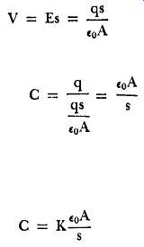
(57)
From Equation 52, C = Q/V and since in this case Q = q, then…
(58)
…if A is in square meters and s is in meters, then C is in farads.
When the dielectric between the plates is some substance other than air or a vacuum, Equation 58 must be changed to
(59)
... where K is the dielectric constant of the substance between the plates. Note the simplicity of these equations. You will recall that fig. 25. A two-plate capacitor.
DIELECTRIC CONST (K)
in Section 13 we eliminated the 4,, from expressions derived from Coulomb's Law by defining the constant E_o, The reason for doing so is now apparent: if the quantity 4,, had not been thus treated, it would appear in this practical equation for capacitance. As one studies further in electrostatic~, the advisability of this step becomes increasingly evident.
Example:
A capacitor of 0.02 µf such as that shown in Fig. 25 is required for a demonstration Tesla coil transformer. The dielectric is to be glass (K = 6) and the plates are to be metal foil measuring 20 x 20 cm each. Calculate the thickness of glass required to obtain this capacitance.
Solution:
Solve Equation 59 for s.
-.,A
•=Kc
= 6 (8.85 X 10⁻¹²) (0.04) = (5.31 X 10^-11) (0.4 X 10^-1)
0.02 X 10^-6 2 X 10^-8
= 1.06 X 10^-4 meter
= 0. 10 exp6 mm
31. The Measurement of Capacitance
There are three common methods of measuring capacitance: the ballistic method, the reactance method, and the bridge method.
Only the ballistic method relies on electrostatic principles, hence it is the only one that we shall deal with here. A ballistic galvanometer is essentially a moving-coil instrument in which the coil has a substantial amount of inertia and is properly damped either by mechanical or electrical methods. The throw of such an instrument due to the impulse of a sudden flow of electricity through the coil is proportional to the quantity of electricity that has passed through it. If a capacitor is discharged through the coil of such an instrument, the discharge interval will be very short, since the resistance of the coil is usually small. With enough inertia, the assumption that the entire discharge occurs before the coil begins to move is an excellent approximation and the relationship is:
Q = KS (60)
… where Q is the charge in coulombs and S is the throw of the ballistic galvanometer in cm. K is the "galvanometer constant." Measurement of capacitance is made by connecting a circuit such as that given in Figure 26. The measurement may be made either on the charge or discharge of the capacitor. When SW-1 is moved to position A, and s,v-2 is also on position A, the unknown capacitor C. charges through the galvanometer whose throw may be noted. This is the charge reading. SW-1 may now be set to position B and the discharge throw reading observed. The discharge and charge throws are now averaged.
If S' is the average throw, C. the unknown capacitance, and the average quantity of electricity is Q', then from Equation 60
Q' = KS' (61)
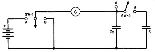
Fig. 26. Circuit for the measurement of capacitance by the ballistic method.
If the voltage applied by the charging source is V, we know from Equation 51 that Q' is also equal to C.V. Equating these values of Q',
C.V = KS' (62)
A standard capacitor, C, of precisely known value is now substituted for C. by moving SW-2 to position B and repeating the process just described. In this case, the deflection of the galvanometer is S, the capacitance C, the galvanometer constant K, and the voltage V. This gives us a similar equation, CV= KS
Dividing Equation 62 by Equation 63,
C.V KS'
CV KS
The V's and K's drop out, leaving
(63)
(64)
32. QUIZ
1. Define the volt in terms of the work done in moving a unit charge. Explain why volts and joules/coulomb are equivalent.
2. Determine the maximum potential to which a sphere of 10-cm radius can be charged.
3. What is meant by potential gradient? What is the relationship between the potential gradient and the electric intensity of a field?
4. Explain why the surface of any charged conductor must be an equipotential surface.
5. Why is it impossible for equipotential surfaces in a finite field to intersect?
6. Why is it believed that the energy of a capacitor resides in the dielectric rather than on the capacitor plates?
7. Find the capacitance of an air-dielectric capacitor consisting of two plates each of 8-cm^2 area and separated by 3 mm.
8. What voltage applied to the terminals of a 0.5-µf capacitor will give it an energy content of 20 joules?
9. Describe the ballistic method of obtaining the capacitance of a capacitor.
10. Explain why the galvanometer constant drops out of the final equation for the ballistic method of determining capacitance. How could you determine the value of this constant for a given galvanometer?