AMAZON multi-meters discounts AMAZON oscilloscope discounts
LEARNING OBJECTIVES:
Upon studying this section on the fabrication of multilayer printed circuit boards, the student should be able to:
1. Understand the basic structure of multilayer boards.
2. Maintain precise registration of all layers.
3. Know the raw materials required to fabricate multilayer boards.
4. Use a laminating fixture to pin and register multilayer boards.
5. Fabricate the inner layers of multilayer boards.
6. Apply a black oxide treatment to the inner layer core.
7. Properly prepare a lay-up book in preparation of pressing a multilayer board.
8. Use a cold press cycle to laminate raw multilayer boards.
9. Drill multilayer boards.
10. Apply an epoxy-smear treatment to drilled boards.
11. Complete the fabrication of multilayer boards.
Since the early 1960s, there has been a continual demand on the packaging de signer to incorporate more electronics into a smaller space in order to reduce both system size and overall weight. With the density of the double-sided pc board being pressed beyond its limits, the industry’s solution is the multilayer board (MLB).
The multilayer board consists of two outer layers of circuitry that sandwich two or more inner layers. The outer layers contain conductor paths and terminal pads and are identical in appearance to standard double-sided boards. Each of the inner layers serves a specific circuit function, as will be explained in subsequent sections. Each of the board layers is separated from the others by sheets of insulating material. The layers are ultimately laminated together under heat and pressure to form a single functional board which is capable of providing more dense circuitry than are double-sided boards.
One method of classifying MLBs is in the manner in which the layers are connected electrically. The most common method of layer-to-layer interconnection is to drill clearance holes (usually lead access holes but via holes are also used) and employ a plated-through-hole technique similar to that used on double-sided boards.
Multilayer boards are also classified by the manner in which the inner layers are used. If conventional circuitry (i.e., terminal pads and conductor paths) is to be designed on one or more inner layers, it is referred to as a signal MLB. On the other hand, if the inner layers are predominantly solid conductive copper planes, they are classified as power/ground or voltage/ground MLBs. For the latter classification, one inner layer is used exclusively for making all circuit ground interconnections, while the other is used for making all the dc voltage interconnections.
In addition to reducing both space and weight, multilayer designs are also used in high-frequency circuits. The use of the large copper planes as ground greatly reduces crosstalk and other forms of interference common to high- frequency circuits. At microwave frequencies, MLBs can be designed to maintain a uniform impedance necessary for proper circuit performance.
The solid copper planes of MLBs may also serve as effective heat sinks in circuits in which excessive heat is generated. For this purpose, the solid planes are used as the outer layers and the inner layers are used for signal paths. In this type of design, the two outer layers may also be used for power and ground while also serving to remove heat from the circuit.
Although the MLB overcomes many design problems, it is the most ex pensive type of pc board to manufacture. This is primarily due to the fixed setup costs, more processing steps, and critical controls and inspections which often result in reduced yields. For these reasons, the use of a multilayer design should be made only after other alternatives and trade-offs have been considered.
The following topics are treated in this section: (1) artworks for MLBs, (2) multilayer material, (3) inner-layer core manufacture, (4) lay-up processes, (5) MLB press, (6) drilling and board preparation, and (7) standard plated-through-hole processing.
1 ARTWORK FOR MULTILAYER BOARDS
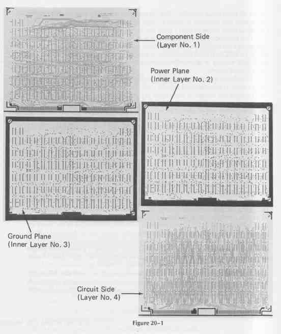
High-quality artwork is absolutely essential for the manufacture of MLBs. The resulting board can be no better than the artwork supplied to the manufacturer. This artwork includes at least one 1 : 1 scale film on a 0.007-inch poly ester backing for each layer of the MLB. These films are generally the result of 4 : 1 scale layouts that are photographically reduced to a 1: 1 scale. For a typical four-layer voltage/ground MLB, positive and negative films are required. These are shown in FIG. 1. Note that the conductor paths (signal traces) appear on only the two outer layers, the component side (layer 1) and the circuit side (layer 4). Film positives are provided for these layers. Layer 2 is positioned below the component side and serves as the voltage or power plane. Layer 3 is the ground plane and is between the power plane and the circuit side (layer 4). Film negatives are providing for the power and ground layers.
In viewing each film shown in FIG. 1, the dark-shaded areas of layers 1 and 4 are to be considered as copper on the finished board and the unshaded areas as insulation (i.e., void of copper). For the inner layers (2 and 3), the dark- shaded areas are to be considered as insulation on the finished board and the unshaded areas as copper.
---FIG.—1
Layer-to-layer registration is accomplished by aligning the three staggered targets as each film is placed upon the other in the lay-up. As can be seen in FIG. 1, both the power and ground inner layers are largely solid planes of copper.
If no electrical connection is to be made between an inner layer and an outer layer, and antipad (clearance area of insulation) is provided around each clearance hole. This antipad is a round or square insulation gap, void of copper, that is at least 0.050 inch larger than the diameter of the hole drilled in that area (see FIG. 2a). This insulation gap ensures that there will be no electrical connection between that layer and the plated barrel of the hole.
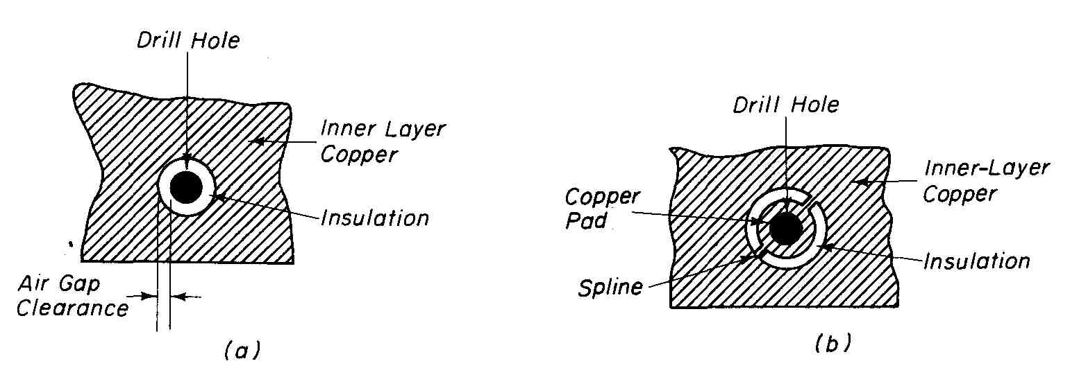
---FIG.—2 Special pad geometries are used on inner layers to provide
isolation or interconnection with hole barrel: (a) antipad; (b) thermal
relief pad.
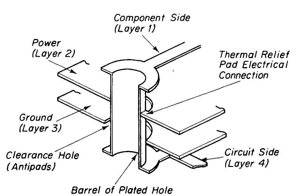
---FIG.—3 Cutaway view showing a properly registered PTH in an MLB.
If an electrical connection is to be made to one of the inner layers, a thermal relief pad is used (see FIG. 2b). The connection is made by drilling a hole through the solid inner pad. This hole will be plated and will connect to the two splines (copper paths) of the pad. The geometry of the thermal relief pad pre vents the occurrence of inferior solder connections in the wave-soldering process. Direct connection of a plated-through hole to a solid copper plane could cause the copper to act as a heat sink, drawing heat away, and result in a poor connection.
One of the major problems in the fabrication of MLBs is maintaining precise layer-to-layer registration. Good design practice dictates that a pad master system for both outer layers be used, followed by careful registration of all anti- pads and thermal relief pads on inner layers. For reasons of placement accuracy, 4:1 scale layouts should be used on all MLB designs. A cutaway view of a properly registered MLB is shown in FIG. 3. It is essential that the following be included in all MLB artworks: (1) all layers clearly marked, (2) corner brackets, (3) reduction scale and tolerances, and (4) tooling or mounting holes clearly identified.
2 RAW MATERIALS USED IN MULTILAYER BOARD FABRICATION
In the design of a standard four-layer voltage/ground MLB, a finished thickness of 0.059 ± 0.005 inch is a typical specification. Due to electrical circuit considerations, different inner-layer thicknesses of insulation as well as their specific location relative to the outer layers may be a design requirement. For these reasons, the laminate suppliers provide stock with dielectric (insulation) thicknesses of 0.002 inch (2 mils) to 0.031 inch (31 mils) in increments of 0.001 inch (1 mil).
A common insulating material used is a fiberglass-cloth epoxy-based material that conforms electrically and mechanically to either grade G-10 or FR-4. (Grades of insulating base material are discussed in Section 10.) This material is completely cured and is called C-stage material. Polymide materials are also available. C-stage laminate is available with copper foil bonded to one or to both sides. The copper thickness varies from ultrathin ounce per square foot (oz/ft.^2 (0.0002 inch or 5 microns) to 10 oz/ft (0.014 inch or 350 microns). Laminates clad with copper on both sides are called cores and are often used to form the inner layers of an MLB. When used in this way, a minimum foil thickness of 2 oz/ft (0.0028 inch or 70 microns) is recommended. C-stage laminates with copper foil on only one side are called cap sheets and are typically used to form the outer layers of an MLB. The foil thickness on cap sheets used on MLBs ranges from oz/ft (0.0008 inch or 20 microns) for fine-line work to 1 oz/ft (0.0014 inch or 35 microns) for normal conductor widths and spacings.
A typical MLB specification for a four-layer voltage/ground design is the following: Core thickness of 0.03 1 inch with 2 oz/ft copper foil on both sides and two cap sheets having a laminate thickness of 0.008 inch (8 mils) with 1 oz/ft copper foil on one side. An exploded view of this type of MLB is shown in FIG. 4.
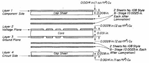
FIG. 4 Exploded side view of a four-layer MLB.
To bond the cap sheets to the processed circuitry on the inner-layer core, several layers of adhesive material are sandwiched between the foil layers to form the finished assembly as shown in FIG. 4. This adhesive is called pre preg or B-stage material. It is composed of thin sheets of fiberglass-cloth impregnated with an epoxy resin that is semicured. Complete curing of prepreg material is accomplished under elevated pressure and temperature in a multi- layer press.
Because prepreg material is semicured and hydroscopic, it will absorb moisture quickly. For this reason it must be carefully stored. Some manufacturers store prepreg material under refrigeration at temperatures ranging from 10 to 50°F in a relative humidity of 50% or less. Others prefer storage in a dry gas atmosphere at or slightly above ambient temperature. Both methods of storage are effective. Because prepreg material can be degraded by extended storage, date codes should be incorporated with the inventory.
--- ---
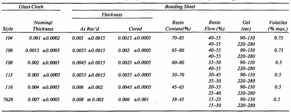
TABLE 1 Epoxy System Multi-Flow Prepreg Bonding Sheets
*Typical glass styles and resin parameters shown. A wide specifications range is necessary to encompass military specifications and customer process variations. Significantly tighter tolerances are maintained on off-the-shelf bonding sheets. All are tested to MIL-G-55636. Multi-Flow prepreg bonding sheets are furnished 38 inches wide in continuous lengths or sheeted to order.
--- ---
Before prepreg material is to be used, it is recommended that it be given a mild prebake cycle or placed in a vacuum chamber. These processes will remove any moisture or volatiles (solvents) which may have been absorbed while in storage. The handling of prepreg material requires that white gloves be worn at all times.
Six commonly used styles of prepreg bonding sheets together with their important characteristics are listed in TABLE 1. Note that the cloth thickness ranges in nominal value from 0.001 to 0.007 inch. With the resin added, the “as received” thickness is approximately 0.002 inch larger than the cloth alone, ranging from 0.003 to 0.008 inch for the styles listed. The cured thickness column in TABLE 1 lists the amount of thickness reduction expected after bonding is completed in the multilayer press. This column is used to determine the finished thickness of the MLB. We will use the example MLB shown in FIG. 4, together with TABLE 1, to determine its finished thickness. Using two sheets of Style 108 prepreg to bond the component side cap sheet to the core and another two sheets to bond the circuit side cap sheet to the core, the resulting cured thickness for each bond will be 0.005 inch (2 x 0.0025) or a total of 0.010 inch added to the overall thickness of the boards. The overall thickness of the finished MLB will thus be the sum of (1) core thickness (0.03 1 inch), (2) two 2-oz/ft inner-layer copper thicknesses at 0.0028 inch per layer, (3) two cap sheets at 0.008 inch each (insulation thickness), and (4) the bonding thickness of 0.0 10 inch. It can be seen that the finished MLB for our example will be approximately 0.062 ( inch.)
Referring again to TABLE 1, note that four additional columns of information are provided to aid in the selection of the style of prepreg material to be used. An explanation of each of these columns follows.
Resin Content. This is a measure of the amount of epoxy resin present in a given sample of prepreg and is specified in percent by weight of the total amount of prepreg. The resin content is an important selection criteria. If this content is too low, a resin-starved bond line will result. With too high a resin content, the resulting bond line will be too thick on the processed inner layers.
Resin Flow. This is a measure of the amount of epoxy resin present in a given sample which will be flowing during the press cycle. Given as percent of average resin content, the flow decreases as the amount available decreases. The concern here is that too little flow can cause too thick a bond line with voids while too high a flow can result in a resin-starved bond line.
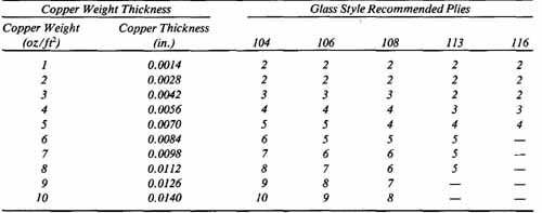
---TABLE 2 Suggested Fill Chart for Epoxy and Polymid Multi-Flow Prepreg
Bonding Sheets ---
*Fill chart based on hypothetical circuitry with 30% copper density.
Gel Time. This is a measure of how long the resin remains molten before getting or solidifying. Within the range 220 to 280°F, the gel time is typically constant from 90 to 130 seconds.
Volatiles. In the manufacture of prepreg, solvents are used to control the viscosity of the resin. These volatiles are only partially driven off since the resin is semicured. Those solvents remaining are expressed as a percent by weight of the total amount of prepreg. Volatiles can cause vapor bubbles or voids between layers. For this reason, a prebake cycle of B-stage material is important to drive off any remaining solvents.
Laminate manufacturers provide useful information to aid the designer and manufacturer of MLBs in selecting the appropriate material. For example, refer to TABLE 2 which lists the recommended number of bonding sheets of B-stage material for specific glass styles and copper foil thicknesses of the core sheet. Using this table and referring to FIG. 4, it can be seen that two sheets of Style 108 prepreg between layers is recommended to properly bond and fill the spaces in etched 2 oz/ft copper foil.
3 LAMINATING FIXTURES AND PINNING
One of the most critical phases in the manufacture of MLBs is the precise layer- to-layer registration of all terminal pads. Because these pads are used for inner- layer interconnections, they must be in exact alignment during inner-layer imaging and in the lay-up in order to successfully drill and plate the MLB. Re call that FIG. 4 shows the side view lay-up of a typical MLB. Precise layer-to- layer registration of the phototools used to manufacture this board is accomplished with a pinning system which is keyed to a set of laminating fix ture plates. These plates are used to hold all layers and materials fixed in close registration tolerance during the laminating press cycle.
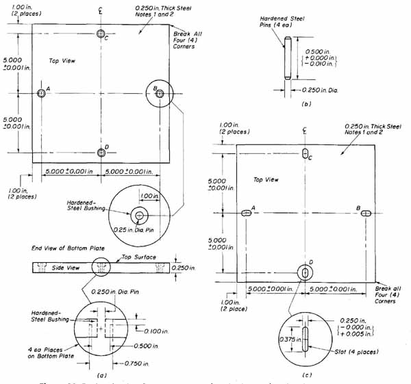
FIG.—5 Laminating fixture geometry for pinning and registering an MLB
lay-up: (a) bottom caul plate; (b) tooling pin; (C) top caul plate.
A typical set of 12- by 12-inch laminating fixtures used for manufacturing MLBs is shown in FIG. 5. The bottom plate (FIG. 5a) is made from 0.250-inch hot-rolled steel stock having a coefficient of thermal expansion similar to that of the pc board stock. This plate is ground to a precision flatness with both surfaces parallel to one another. The plate is fitted with four hardened steel tooling pins (FIG. 5b) having a diameter of 0.250 inch and made to “snug” fit into four hardened steel bushings. For the MLB lay-up shown in FIG. 4, the length of the pin should be 0.500 inch. It is essential that the length of the pin be less than the total thickness of the top and bottom plates plus that of the finished thickness of the MLB. If the pin is longer than this combination, it will cause damage to the press. Since the positions of the four toolings pins are accurately laid out, precise alignment of all artwork phototools with these pins will result in exact layer-to-layer registration.
The top laminating fixture (FIG. 5c) fits over the bottom plate with the MLB lay-up sandwiched between them for pressing. The top plate is also made from the same 0.250-inch hot-rolled steel stock with both flatness and parallel ism specifications identical to those of the bottom plate. This plate is provided with four slots to accept the tooling pins for proper registration and to allow for material expansion. The width of each slot is made slightly larger than the 0.250-inch-diameter tooling pin it is to accept.
The 12- by 12-inch laminating fixture just described is used for registration purposes in the following manner. The MLB raw stock (core, cap sheets, and B-stage) is first cut to 11 by 11 inches. All the stock is then slotted with the same configuration as on the top plate of the fixture and in precise alignment with the pins of the bottom plate. The slots in the MLB material are made with an air-actuated punch which automatically aligns and forms the four slots simultaneously.
Note in FIG. 5c that opposite slots in the top plate are in the same direction and that adjacent slots are perpendicular to one another. The reason for this slotting configuration is to allow for heat expansion in the press. When heated in the press, both the pinned pc board stock and the bottom plate expand along the x and y planes. Slots A and B in the top plate and in the board material allow space for expansion in the x direction. The edges of pins C and D hold the exact center of the board stock between pins A and B in a fixed position and allow the expansion error to be split in half on either side of this center. In a similar fashion, slots C and D allow expansion in they direction. Again, the expansion error due to heat is split in half on either side of the center, which is held in a fixed position by the edges of pins A and B.
With the four slots punched into the pc board stock, the phototools for each layer of the MLB are punched with the same four slots in the same orientation. These slots are also aligned with the tooling pins of the laminating fix ture. In this way all phototools are precisely registered to one another for layer-to-layer alignment and all material is registered to the phototools through these series of four slots. In the following section, the core layers of an MLB will be fabricated using the alignment techniques just discussed.
4 INNER-LAYER FABRICATION
After the slots have been punched into the core and cap sheets for positioning onto the laminating fixture, the next phase in MLB fabrication is to subject all the C-stage raw stock to an initial oven baked cycle to reduce internal stresses, thereby improving the dimensional stability of the material. A 6- to 8-hour bake at 300°F is recommended for this cycle. During this baking cycle, the material, which is very thin, will tend to soften. For this reason, the sheets should be racked rather than laying one on top of the other. Racks with vertical slots will support the edges of the sheets and prevent sagging.
When the C-stage material has returned to room temperature, it can be processed into the inner-layer voltage and ground patterns. We will use the lay- up of the MLB shown in FIG. 4 as an example. Both the voltage and ground patterns of the inner layers are processed simultaneously. The flow chart of FIG. 6 shows the sequential processes involved. With the exception of the last step (black oxide treatment), you will note that the flow chart is similar to that of the print-and-etch processes discussed in earlier sections. These processes should be reviewed before continuing on in this section.
Both copper surfaces of the core are first chemically cleaned in a 10% H acid dip. This is followed by a water rinse. The core is then mechanically scrubbed and air-knife dried. In preparation for dry-film photo-resist laminating, the core is baked at 150°F for 15 minutes. Proper racking of the core during this bake cycle is important to prevent sagging. The core is removed from the oven and immediately laminated on both sides with 1-mil Dynachem Laminar AX photo-resist (see Section 18). The excess resist is trimmed along all edges. All tooling holes are carefully cleaned of resist with a sharp scalpel. After laminating, a hold time of 30 minutes is allowed to improve photo-resist adhesion to the copper surfaces.
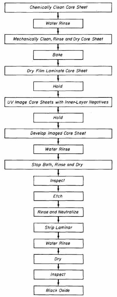
--- FIG.—6 Flow chart for inner-layer fabrication by the print-and-etch
process.
To establish the proper layer-to-layer registration between the inner layers, the voltage and ground-layer phototools are secured to the core with two Carison pins (see FIG. 7). The pins are 0.250 inch in diameter and approximately 0.055 inch long. The phototools are positioned one above and one below the slotted core stock and pinned into registration.
FIG.—7 Inner-layer registration is established through the use of Carlson
pins.
Once registered, the core is processed through the print-and-etch Sequences. After exposure, the core is again allowed a holding time of 30 minutes, after which it is developed. Laminar AX resist is developed by first removing the gas seals from both sides of the exposed core sheet. Both sides are then spray-developed for approximately 45 seconds at a developing solution temperature of 85°F. The developing process is immediately followed by immersing the core sheet into a stop bath of 10% sulfuric acid to neutralize the developing action. The image should be developed to a solid 4 on the Stouffer table.
After the core has been developed and neutralized, it is ready to be etched. Any of the common etchants, such as ferric chloride, ammonium persulfate, peroxide/sulfuric, or ammoniated etchants may be used. Once the core has been etched, it is immediately rinsed in tap water. Depending upon which type of etchant solution is used, an appropriate neutralizing step may be necessary. The circuit features now appear on the voltage and ground layers. Since the photo-resist is no longer required, it is stripped from both sides of the core. Time in the stripper bath must be held to an absolute minimum to reduce the amount of methylene chloride which is absorbed by the epoxy substrate. A final water rinse follows the stripping process and the core is allowed to dry.
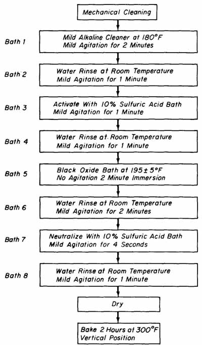
FIG.—8 Flow chart for black oxide treatment.
To improve laminated bonding to the large copper areas of the inner layers, the core is treated with a black oxide solution. (Recall that this treatment was not discussed in the detailed description of the print-and-etch technique presented in previous sections.) This commercially available solution chemically provides a heavy cupric oxide coating, which increases the copper surface area by roughening the copper. A flow chart showing the process for a typical black oxide treatment is shown in FIG. 8. The core is first mechanically cleaned using a conveyorized cleaning machine such as that shown in Fig. 18.3b. The core is then racked and passed through a series of eight baths as described here.
Bath 1. A 2-minute dip in a mild alkaline cleaner at an operating temperature of 180°F to remove fingerprints, greases, and oils.
Bath 2. A 1-minute water rinse at room temperature.
Bath 3. A 1-minute dip in a 10% solution of sulfuric acid, which serves as an activator.
Bath 4. A 1-minute water rinse at room temperature.
Bath 5. Black oxide solution which is heated to 190 50 F. Rapid immersion into this bath is essential so that the clean copper does not begin to oxidize from the heat generated by the solution. The core remains in this bath for approximately 2 minutes and should not be agitated.
Bath 6. A 1-minute water rinse at room temperature.
Bath 7. A 10% sulfuric acid bath to neutralize hydroxyl ions present after the black oxide treatment. If not removed, these hydroxyl ions will adversely affect the B-stage material by causing voids to occur in the MLB. The core should remain in this bath for 2 to 4 seconds.
Bath 8. A 1-minute water rinse at room temperature.
After the core has been processed through the eight baths and dried, the copper surfaces will appear as a uniform gray-black color on both sides.
The final preparation of the core prior to the laminating process is another oven bake cycle for 2 hours at 300°F. When processing several cores, they must not be stacked one on top of the other but rather separated and positioned vertically in the oven. In addition, care should be taken to prevent scratching the black oxide surfaces. White cotton gloves should be worn to prevent oils and greases from contaminating these surfaces. The final bake cycle is required to remove water and solvents that were absorbed in the previous processing steps. This removal is essential to eliminate voids due to moisture absorption by the core.
5 MULTILAYER LAY-UP PROCESS
After the inner layers of an MLB have been processed through the black oxide treatment and final bake cycle, they are ready to be pinned together with the two outside layers and other elements to complete the lay-up of the multilayer book which will then be pressed into the raw MLB. The press cycle is discussed in the following section.
The lay-up on an MLB should be performed in a dust-free, positive-pres sure room which is environmentally controlled at 70°F and 50% RH. All technicians working in the lay-up room should wear white cotton gloves.
The assembly of the MLB book begins by cleaning and inspecting the bottom laminating plate (caul plate). The work surface should be free of all foreign matter by cleaning with lint-free cloth saturated in trichlorethylene. The tooling pins are next installed into the bottom fixture plate. The side view of a lay- up sequence to press two identical MLBs between one set of 12- by 12-inch caul plates is shown in FIG. 9. (Typically, four to five MLBs are pressed in a book at one time.) Referring to FIG. 9, the construction of the MLB book is per formed in the following sequence with each step numbered in the figure.
1. The cleaned bottom caul plate, with the tooling pins installed flush to the bottom surface of the plate, is placed on a worktable.
2. A sheet of mold-release material is cut so that its dimensions are approximately 1 inch larger than the caul plate on all four sides. For a 12- by 12- inch plate, the mold release sheet would be cut to a dimension of 14 by 14 inches. This prevents sticking between the pc boards, the caul plates, and separator plates. Various materials, such as Tedlar, PTFE sheeting, kraft paper, or chipboard, are used as mold-release material. These materials will not contaminate the MLB with agents of their own. With a deep throated hand-operated paper punch, four i-inch-diameter holes are punched into the release sheet, aligning them with the four tooling pins. The mold-release sheet is then positioned over the bottom caul plate.
3. With the tooling pins used for alignment, the 11- by 11-inch bottom cap sheet (layer 4) is placed over the mold-release sheet with its copper surface facing downward. (Recall from Sec. 20.4 that this cap sheet has been stress-relieved for 6 hours at 300°F.)
4. Two sheets of Style 108 B-stage material (as recommended in TABLE 2) are cut to the same size as the raw stock (11 by 11 inches). One-half-inch holes are also punched into this material, again to align with the tooling holes. The prepreg sheets should be allowed to stabilize for at least 24 hours at room temperature at no more than 50% RH prior to being in stalled in the lay-up. A J-type thermocouple is inserted into a bond line, between the two prepreg sheets approximately 1 inch from the outer edge (see FIG. 9). This will be used to monitor the thermal profile of the press cycle as discussed in Sec. 6.
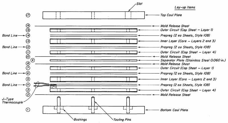
---FIG.—9 Exploded side view of a book having a lay-up to press two
MLBs.
5. A previously processed and black-oxide-treated core (inner layers 2 and 3) is pinned to the assembly using the slotted holes and tooling pins for alignment. The assembly instructions should be consulted for the correct orientation of the core. In our assembly, layer 3 (ground) will face down ward.
6. Two sheets of Style 108 prepreg material are placed above the inner layer in a similar fashion to that described in step 4.
7. A cap sheet (layer 1) is positioned above the prepreg material and aligned using the tooling holes. The solid copper surface of layer 1 is made to face upward.
8. Another 14- by 14-inch sheet of mold-release material is prepared similar to that described in step 2 and placed above the top cap sheet. This completes the lay-up for one of two MLBs to be placed between the same pair of laminating fixture plates.
9. To separate the two MLBs in the laminating fixture, a 12- by 12-inch stainless steel separator plate is positioned above the mold-release material described in step 8. This separator plate has a typical thickness of 0.050 inch and it is provided with four oversized holes aligned with the tooling pins.
10—16. The procedures described in steps 2 through 8 are repeated to assemble the top MLB with the exception of omitting the J-type thermocouple.
17. After the top MLB has been assembled above the stainless steel separator plate, the top caul plate of the fixture is assembled over the top mold- release sheet using the tooling pins and slots for alignment.
The lay-up book for two MLBs just described is now ready to be pressed into raw MLBs. This assembly can be made to accommodate up to five MLBs in a single book by the addition of a separator plate and mold-release material for each additional MLB and increasing the length of the tooling pins as required.
6 MULTILAYER COLD PRESS CYCLE
The application of both pressure and temperature is required to laminate the book shown in FIG. 9 to result in two identical MLBs. This lamination process is accomplished with a multilayer press and subjecting the MLBs to a cold press cycle. (This term is derived from the fact that the pressing cycle is initiated at room temperature.) A basic unit for laminating MLBs consists of a single opening press with two platens, that are electrically or steam heated to the recommended temperature. These platens are also equipped with cool-down coils. The primary requirements of the platens is that they be perfectly flat and possess thermal uniformity throughout their surfaces. Pressure is applied pneumatically or hydraulically. Controls which set, control, and monitor temperature, pressure, and time are also a requirement of the laminating press. A typical small-production MLB press is shown in FIG. 10.
Because the controls are not identical on different presses, a general operating procedure will be described here. Pressing a book such as that discussed in the preceding section begins by cutting four sheets of 90-pound-weight kraft paper or chipboard to a size that is at least 2 inches larger all around than the laminating fixture plates. For our example, 12- by 12-inch caul plates, the sheets should be approximately 16 by 16 inches. These layers are used to keep the platens clean but also serve to slightly adjust the thermal profile of the book as the press cycle is initiated. The number of sheets applied determines the rate at which heat is imparted from the platens to the book to fit the recommended thermal profile. For our example press cycle, we will use two sheets of kraft paper positioned on the bottom platen. The book is placed onto the paper and centered on the platen. The two remaining sheets of kraft paper are placed over the top caul plate. This arrangement of the book and the kraft paper positioned in the press is shown in FIG. 11.
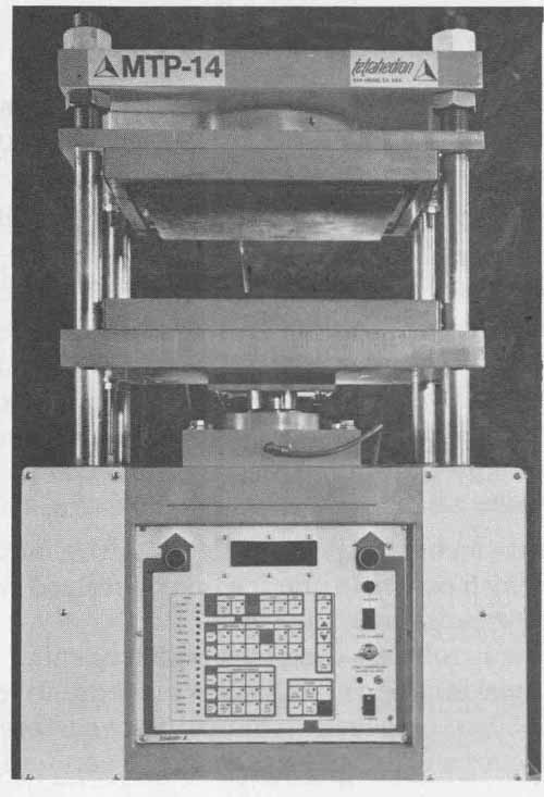
FIG.—10 Small production MLB press.
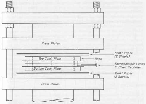
FIG.—11 Placement of book between plates in preparation for press cycle.
Before the press cycle is initiated, the thermocouple wires extending out ward from the book should be connected to the appropriate terminals of a chart recorder. Typically, the constantan wire connects to the — terminal and the iron wire to the + terminal of the recorder. The thermocouple leads are shown in FIG. 11.
With power applied to the recorder and to the laminating press, both platens are set to 3450 ±5°F. The timing controls should be set as follows:
Initial heat-up: 30 minutes
Cure: 1 hour
Cool-down: typically 15 to 30 minutes
This timing represents an overall press cycle of approximately 2 hours. A typical thermal profile which occurs inside the book obtained from the thermocouple and the chart recorder is shown in FIG. 12.
With all of the controls set, the press platen opening (space between the top and bottom platens) is closed and the pressure adjustment control is immediately set to apply 350 psi pressure to the caul plate surface. Our 12- by 12-inch plates have a surface area of 144 square inches. Therefore, the required pres sure P is
P=144 sq in. x 350 lbs/sq. in. = 50,400 pounds
This pressure of approximately 25 tons should be set and maintained throughout the press cycle.
Refer again to FIG. 12 to observe the temperature profile over the en tire press cycle. As the temperature of the platens rises from approximately 70°F toward 350°F, it passes through 200 to 210°F, where the Style 108 B- stage material begins to flow. To maintain good resin flow, the stack tempera ture should be controlled at a rate of 8 to 10°F rise per minute from 200 to 300°F. During this resin-flow cycle, air is forced out of the inner layer, filling in all of the tiny voids between circuit features with molten resin. As the stack temperature rises above 280 to 290 °F, the resin stops flowing and begins to solidify. The cure continues with increasing temperature. After approximately 60 minutes, resin stiffening occurs, and molecular cross-linking results in a homogeneous mass.
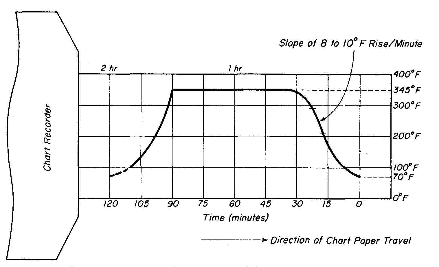
FIG.—12 Thermal profile of a multilayer cold press cycle.
After the cure cycle is complete (1 hour), the cool-down cycle begins. The book is frozen by bringing the temperature of the platens down from approximately 345°F to below 100°F in 15 to 30 minutes. The recommended rate of temperature change during the cool-down cycle is again 8 to 10°F per minute.
With the cool-down cycle complete, the book is removed from the press. The pins are then extracted from the caul plate and the MLBs are removed. The mold-release and kraft paper sheets are discarded and any resin seepage around the edges of the stack is trimmed off. To reduce any internal stresses that have occurred during the pressing operation, the MLBs are weighted with steel plates and baked for 2 hours at a temperature of 250°F.
7 DRILLING MUETILAYER PRINTED CIRCUIT BOARDS
The raw MLBs that were laminated in the preceding section now appear as double-sided pc board raw stock containing tooling holes. These boards are now ready to be drilled on an NC or CNC drilling machine. Recall from Section 17 that the panel is pinned with backup material and a thin sheet of aluminum as top drill-entry material.
The drill operator is provided with the proper drill program for the MLB together with instructions on the stack-up (i.e., number of MLBs to be stacked and drilled simultaneously). Typically, MLBs are drilled one-up (a single board at a time). However, depending upon the thickness and the amount of hole- position tolerance that must be maintained, several boards may be stacked and drilled together.
One of the most serious problems that face the MLB manufacturer is called epoxy smear, which is the result of the drilling operation. As the drill bit passes through the copper and epoxy-glass material it generates heat (above 350° F) due to friction as it cuts through the copper. This heat melts some of the epoxy inner layer and the molten resin is dragged across the entire barrel of the hole as the bit is withdrawn. As it cools, the epoxy forms an insulating layer which will prevent electrical interconnection between the inner and outer layers by way of the plated-through hole. Although it is possible to reduce the amount of epoxy smear, it cannot be completely eliminated due to the nature of the drilling process. Epoxy smear generation is dependent upon the drill bit geometry, the speed and feed rate adjustment, the number of hits before bit replacement, the flatness and type of entry material, the type of backup material, and the amount of board cure before drilling. The use of resharpened drill bits should be avoided. It can be seen that many factors contribute to the generation of epoxy smear and it can be held to a minimum by carefully controlling these factors. However, a post-drilling smear removal process is necessary to improve the reliability of inner-layer interconnection in the plated-through-hole process. This removal process will be discussed in the following section.
8 EPOXY SMEAR REMOVAL AND ETCHBACK
After the board has been drilled, it is subjected to an epoxy smear removal process before continuing with its fabrication. This epoxy smear removal process should have the characteristics to produce three specific results. The first is the complete removal of the epoxy residue resulting from the drilling operation. The second is to produce a positive etchback of the cured epoxy between all layers of copper. This etchback is typically specified as a minimum of 0.0002 inch to a maximum of 0.003 inch. The etchback process produces an inner layer foot to obtain a reliable three-point electrical contact that will result during the plating process (see FIG. 13). The third is to etch the fiberglass material of the inner layers and condition (roughen) the epoxy surface to improve electro less copper-plating adhesion.
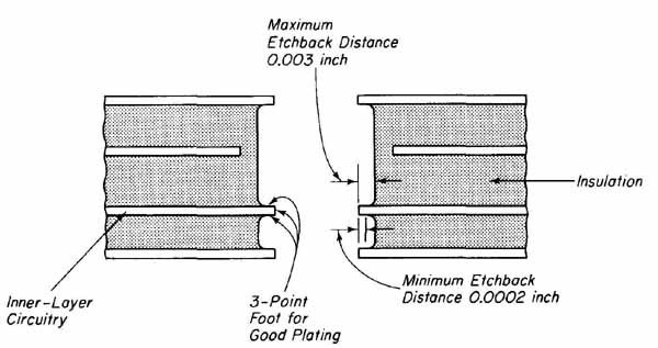
--- FIG.—13 Etchback produces a superior surface geometry for the formation
of a PTH.
Although there is no universally accepted process for accomplishing the three characteristics outlined, we will present a de-smear/etchback process that is a generally accepted standard and currently used in the industry. This process is shown in flow-chart form in FIG. 14. Each of the steps will be discussed with reference to this flow chart.
Bath 1. The boards are racked horizontally and immersed in concentrated sulfuric acid at 80°F for 15 to 30 seconds. Extreme care must be exercised when working with this concentrated acid bath. This bath will remove the epoxy smear and etchback the inner-layer epoxy material. The degree of removal is a function of time, temperature, acid concentration, and the amount of agitation of the board. Increasing the time above 30 seconds does not improve etchback, apparently due to the fact that fresh acid cannot contact with the epoxy surface. Increasing the temperature does, however, reduce the viscosity of the acid and improves its solvent action. When the concentration of acid is diluted to below approximately 92%, the solvent action is severely impaired and the bath should be replaced. Vigorous up-and-down board agitation improves solution flow in the holes and improves etchback.
Bath 2. The boards are removed from the sulfuric acid bath, allowed to drain, and then immersed in a 50% sulfuric acid rinse at 120°F for a minimum of 5 minutes. This bath will prevent epoxy residue from being redeposited in the holes. The board is mildly agitated in this bath.
Bath 3. This is a water rinse heated to 120°F. The board is immersed in this bath and mildly agitated for 2 minutes. This will flush the holes free of any remaining residue.
Bath 4. This glass-etching bath is made up of 1.5 pounds per gallon of ammonium biflouride and 1 to 3% by volume of hydrochloric acid and is operated at room temperature. The board is mildly agitated in this bath for 3 to 5 minutes. This bath will etch away the protruding glass fibers.
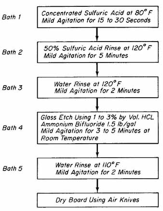
---FIG.—14 Flow chart for smear removal and etchback process.
Bath 5. The board is placed in a final warm-water (110°F) rinse and mildly agitated for 2 minutes.
Finally, the board is dried and is ready for the succeeding fabrication processes.
9 FINAL MULTILAYER BOARD PROCESSING
With the completion of the smear removal and etchback processes, the MLB is next processed in an identical manner to that of a double-sided pc board. These processes will not be repeated here, but sections can be referenced where de tailed information of each is provided.
The MLB is first passed through an electroless copper deposition line to initially form the plated-through holes (Section 17). This is followed by copper flash plating (also Section 17). The two outer layers (layers 1 and 4) are then laminated with dry-film photo-resist (Section 18). Copper and solder pattern plating is next applied to the total pattern (Section 19), which completes the formation of the plated-through holes. The board is etched (Section 19) to result in the final conductor patterns on layers 1 and 4. Upon studying the etching process, the board is profiled to size and shape (Section 19), which results in a finished multilayer pc board.
EXERCISES:
A. Questions
1. Explain the basic difference between a signal MLB and a voltage/ground MLB.
2. What are the advantages of using solid copper planes in MLB construction?
3. Define the purpose of (a) an antipad and (b) a thermal relief pad.
4. (a) If 3 oz/ft inner-layer copper is used in an MLB design, how many layers of Style 105 prepreg material should be used to obtain a good bond with a cap sheet? Refer to TABLE 2. (b) For the same MLB de sign, how many layers of Styles 106, 108, 113, and 116 should be used?
5. Using TABLE 1, determine the cured thickness (i.e., after pressing) for three sheets of Style 113 prepreg material.
6. A four-layer power/ground MLB is to be fabricated with a 0.020-inch core having 4 oz/ft copper on both sides. Two outer-layer cap sheets, each having an insulation thickness of 0.020 inch, are to be bonded to the core using Style 113 prepreg material. Determine (a) the number of layers of B-stage material to be used to bond each cap sheet and (b) the overall thickness of the cured MLB.
7. Explain the purpose of the slotted design in the top laminating fixture.
8. Explain the purpose and use of Carlson pins for inner-layer fabrication.
9 What is the purpose of the black oxide treatment?
10. List the elements in their correct order to assemble a single four-layer MLB book.
11. In what portion of the press cycle (see FIG..12) and between what temperatures does resin flow occur?
12. How does etchback improve the condition of the barrels in an MLB to obtain good-quality electrical interconnections?
13. What is the difference between B-stage and C-stage materials?
14. What are cap sheets, and where are they used?
15. How is the thermal profile of the press cycle monitored?
16. What is epoxy smear, and what is its cause?
B. True or False
Circle T if the statement is true, or F if any part of the statement is false.
1. MLBs are classified as power/ground if the outer layers are predominantly solid conductive copper planes. T F
2. For a four-layer voltage/ground MLB, positive phototools are required for the outer layers and negative phototools for processing the inner layers. T F
3. Thermal relief pads and antipads are found only on internal layers of a MLB. T F
4. B-stage material is used to form the outer layers of a MLB. T F
5. If there is too little resin flow during the press cycle, a resin-starved bond line will result. T F
6. Caul plates are made from steel stock whose coefficient of thermal expansion is the same as the pc board stock. T F
7. Black oxide solution is used to improve laminate bonding to the copper areas of the inner layers of a MLB. T F
8. Only one MLB at a time can be pressed between a set of caul plates. T F
9. The required pressure applied to a MLB in the press cycle is approximately 25 tons. T F
10. Epoxy smear is caused by the heat generated from the drilling operation. T F
C. Multiple Choice
Circle the correct answer for each statement.
1 Completely cured pc board material is called (B-stage, C-stage) while partially cured material is called (B-stage, C-stage).
2 Cap sheets are typically pc board material with copper foil on (one, two) sides.
3 Improved laminate bonding between the large copper areas of the inner layers results by treating the core material with (etch back, black oxide) solution.
4 The cold press cycle in the fabrication of MLBs requires a 1-hour cure cycle at a temperature of (345°F, 145°F).
5 Typically, MLBs are drilled (one, two, three) at a time.
6 Laminating fixtures for MLB fabrication are made from (stainless, hot- rolled) steel which approximates the coefficient of thermal expansion of pc board stock.
D. Matching Columns
Match each item in column A to the most appropriate item in column B.
COLUMN A | COLUMN B
1. Caul plate 2. Prepreg 3. Mold release 4. Antipad 5. Epoxy smear 6. Thermal relief pad 7. Cold press cycle 8. Core material |
a. Etchback b. Inner-layer interconnection c. Double-sided pc board d. B-stage e. Two hours f. Laminating fixture g. Clearance area h. Kraft paper |