Simple circuit generates both white and pink noise.
NOISE is generally an undesirable phenomena that degrades the performance of many measurement and instrumentation systems. It therefore seems strange that anyone should want to generate noise, but this is often the case.
Noise generators are often used to inject noise into radio-frequency amplifiers in order to evaluate their small signal performance. They are also used to test audio systems, and as random signal sources for wind-like effects in electronic music.
There are two commonly used noise source characteristics, 'pink' and 'white'. White noise is so called because it has equal noise energy in equal bandwidths over the total frequency range of interest. Thus, for example, a white noise source would have equal energy in the band 100 to 200 Hz to that in the band 5000 to 5100 Hz.
----------
HOW IT WORKS - ETI 441
In the days when vacuum tubes were in common use the most commonly used form of noise generator was a vacuum-tube diode operated in the current saturation mode. Nowadays noise generators may be very complex indeed. Highly complex digital generators which produce pseudo-random digital noise may cost many thousands of dollars.
An example of a simpler type of digital noise source may be found in our synthesizer design ( see International Music Synthesizer 4600 ETI December 1973). However for audio work of a general nature the most commonly used, and the simplest, method is to use a zener diode as a noise generator.
Transistor Q1 is in fact used as a zener diode. The normal base-emitter junction is reverse-biased and goes into zener break-down at about 7 to 8 volts. The zener noise current from Q1 flows into the base of Q2 such that an output of about 150 millivolts of white noise is available.
The 'zener', besides being the noise source, also biases Q2 correctly, and the noise output of Q2 is fed directly to the White Noise output.
To convert the white noise to pink a filter is required which provides a 3 dB cut per octave as the frequency increases. A conventional RC network is not suitable as a single RC stage ¡eves a cut of 6 dB per octave.
Hence a special network of Rs and Cs is required in order to approximate the 3 dB-per-octave slope required.
Since such a filter attenuates the noise considerably an amplifier is used to restore the output level.
Transistor Q3 is this amplifier and the pink noise filter is connected as a feedback network between collector and base in order to obtain the required characteristic by controlling the gain-versus-frequency of the transistor. The output of transistor Q3 is thus the pink-noise required and is fed to the relevant output socket.
----------------
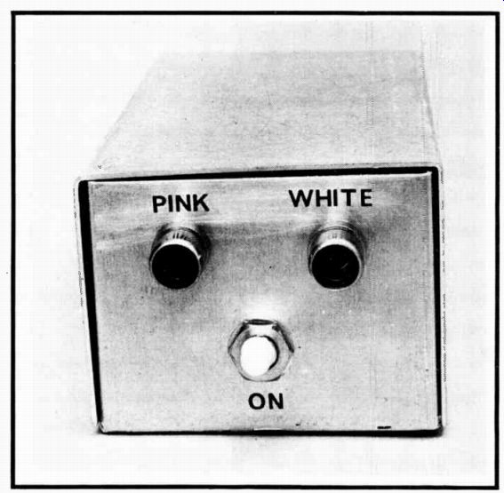
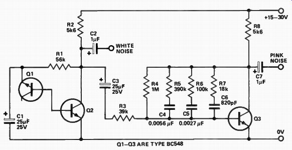
Fig. 1. Circuit diagram of the noise generator.
If white noise is filtered or modified in any way it is referred to as colored noise or, often more specifically, as 'pink' or 'grey' noise. The term pink noise should be restricted to the noise characteristic that has equal energy per percentage change in bandwidth. For example with true pink noise the energy between 100 Hz and 200 Hz should equal that between 5000 Hz and 10 000 Hz ( 100% change in both cases). Pink noise therefore appears to have more bass content than does white noise, and it appears to the ear to have a more uniform output level in audio testing. To change white noise to pink noise a filter is required that reduces the output level by 3 dB per octave (10 dB per decade) as the frequency is increased. The ETI 441 Noise Generator is designed to provide both white and pink noise as required.
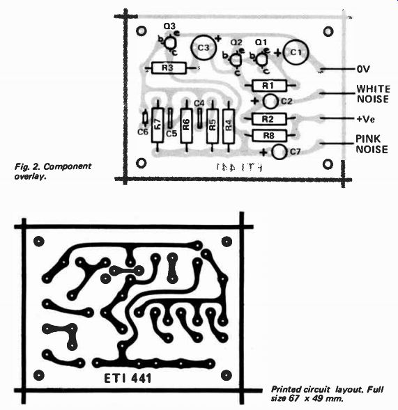
Fig. 2. Component overlay.
----------- Printed circuit layout.
Full size 67 x 49 mm.
-------------
PARTS LIST
- ETI 441
R1 R2 R3 R4 R5 R6 R7 R8
C1 C2 C3 C4 C5 C6 C7
Resistor
Capacitor 56k 1 / 2 W 5% 5k6 1/2W 5% 39k l/zW 5% 1M 1 / 2 W 5% 390k 1 / 2 W 5% 100k 1/2W 5% 18k 1/2W 5% 5k6 1/2W 5% 25uF 25V electro 1 25V electro 25uF 25V electro
0.0056 uF polyester
0.0027uF polyester
820pF ceramic
1uF 25V electro
Q1-Q3
Transistor BC548, BC108 or similar PC board
ETI 441 CASE
BATTERIES OUTPUT SOCKETS
----------------
CONSTRUCTION
Construction is relatively simple and almost any of the common methods, such as Veroboard or Matrix board, may be used if desired. For neatness and ease of assembly it is hard to beat a proper printed-circuit board and for this reason we have provided details of a suitable board.
Almost any type of NPN transistor will do for the generator provided that the one used for G3 has a gain of 100 or more. If BC548 type are used watch out for the two different pin connections used by different manufacturers.
For use as a separate instrument in general experimentation the unit will need to be powered by a pair of nine-volt batteries. However if the unit is to be built into some other piece of equipment, as is often the case, any supply within the equipment which has an output of between 15 and 30 volts dc will be suitable.
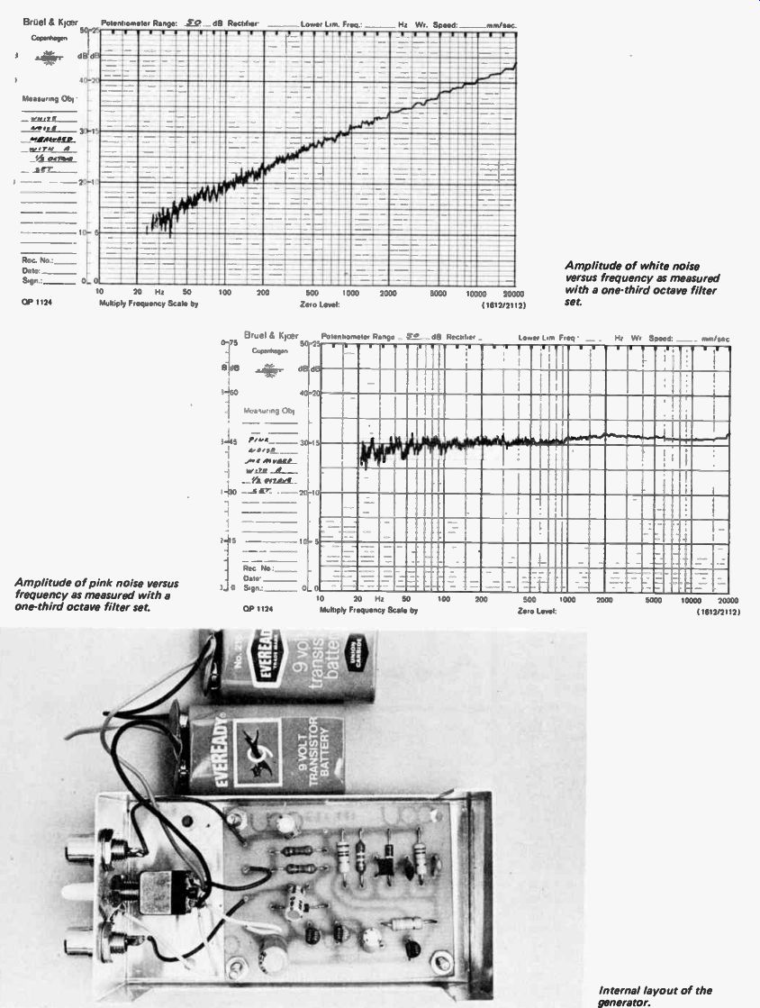
--------------- Amplitude of white noise versus frequency as measured with a one-third octave filter set.
-------------- Amplitude of pink noise versus frequency as measured with a one-third octave filter set.
-------------- internal layout of the generator.
--------------