Measure and test your transistors with this easily built device.
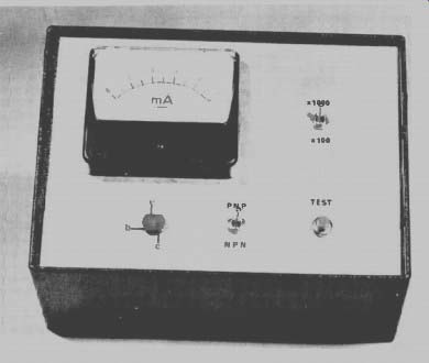
------ The transistor tester mounted in a metal case.
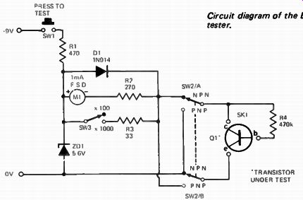
below: Circuit diagram of the ETI transistor tester.
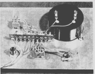
------ The construction method may readily be seen from this photograph
of the back of the front panel.
---------
PARTS LIST - Transistor Tester
- ETI 222
R3 Resistor 33S- 2 1 / 2 watt 5%
Resistor
R2 270 ohm 1 / 2 watt 5%
R1
Resistor
470 1 / 2 watt 5%
R4
Resistor 470k 1/2 watt 5%
D1 Diode IN914
ZDI
Zener diode SZY88C5V6 SW1
Push button push-to-make SW2
Switch toggle DPST SW3
Switch toggle SPST 9V battery
M1 Meter 1 mA movement
SKI Socket
TO5 transistor type
Metal case or minibox
-------------------
HOW IT WORKS
Operation of the tester is very simple. The meter, M1, monitors the collector current of the transistor under test whilst R4 supplies a current of about 10 µA into the base of the test transistor. Thus, on the 1000 range, the maximum collector current will be 1 mA and, on the 100 Beta range, 10 mA. Switch SW3 therefore changes the meter sensitivity according to the beta range selected.
The meter is protected by means of D1 against damage due to test transistors being shorted. The zener diode ZD1 stabilizes the battery voltage to 5.6V.
-------------------
EXPERIMENTERS will frequently use the same transistors in a whole sequence of experimental circuits, for recovering and re-using such components saves considerable outlay.
But semiconductors are easily damaged -- by incorrect operating conditions -- or by excessive application of heat when soldering.
Only too often a malfunctioning experimental circuit will be checked and rechecked before one realizes that a transistor is dead.
A transistor tester will save hours of such frustrating and unproductive effort.
Transistors can often be bought cheaply in bulk -- usually in unmarked and untested lots -- or recovered from old computer boards. Here again a transistor tester will prove invaluable in eliminating the faulty bits.
The simple transistor tester described in this project not only sorts out the good from the bad but indicates also the approximate gain ( e) of the transistor. This is a most useful feature for those circuits where transistors need to be matched. Two ranges of gain ( beta) are provided, 0-100, and 0-1000. The tester may also be used to check transistor polarity.
--------