Converter connects to any analogue or digital meter.
OUR original design concept for this unit was as a complete instrument based on our ETI 533 digital display using a forward biased diode as the sensor -- this generating a temperature -- proportional voltage which in turn is supplied to a voltage-to-frequency converter. We planned to use a timebase to generate the necessary strobe and reset pulses. However the cost and complexity of this arrangement was such that we decided against it.
What finally emerged was a simple temperature-to- voltage converter which can be used in front of any analogue or digital meter. The converter provides an output of 10 mV / degree which can be either Celsius or Fahrenheit depending on calibration. If a dedicated digital readout is required we suggest that you incorporate the converter with our ETI 118 digital voltmeter.
CONSTRUCTION
Whilst a printed-circuit board is by no means essential, using one certainly makes construction easier and improves the appearance. The potentiometers as shown in our prototype are single turn presets which are quite adequate if an analogue meter is to be used for the readout.
However if a digital meter is to be used the extra accuracy of the readout would warrant ten-turn presets being used for RV1 and RV2, as setting accuracy is considerably improved.
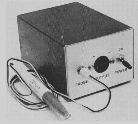
The converter quite readily fits into a small aluminum mini-box. Two nine volt batteries are used to power the unit and battery drain is low enough to ensure a life of many months.
A 3.5 mm jack is used to connect the sensor to the unit and the output to the meter is provided via an inexpensive two-pin speaker socket.
The probe is constructed by mounting the sensor-diode into the tip of a ball-point pen casing, or similar. The method may best be understood by reference to the drawing.
CALIBRATION
To calibrate the instrument, two accurately known temperatures are required. One may be water or oil at room temperature ( ice water should not be used as there the temperature may vary several degrees between different points in the solution). The high temperature is best obtained by heating oil or water and allowing it to stabilize at around 800C. A second smaller heat conductive container filled with water is then immersed in the larger container. This simple procedure prevents errors due to circulating currents in the larger volume of water. An accurate mercury-in-glass thermometer should be used to measure temperatures during the calibration procedure as detailed below.
--------------
SPECIFICATION
RANGE OUTPUT ACCURACY RESPONSE TIME
0 to 100oC 32 to 212°F 10 mV/degree
+ 1° 3 seconds
--------------
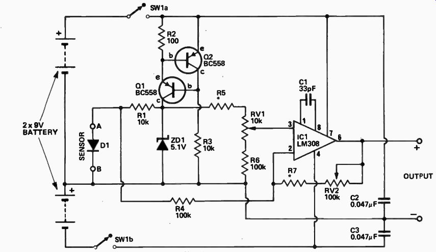
Fig. 1. Circuit diagram of the temperature meter.
NOTE FOR DEGREES F
R5 = 750k R7 -- 820k
FOR DEGREES C
R5 = 910k R7 = 470k
-------------------
1. Place the sensor and thermometer into the cool solution, allow a little time for stabilization, and then measure the voltage from the converter and the temperature. Record these two readings.
2. Place the sensor and thermometer into the hot solution and measure the voltage and temperature as before. The voltage change between the first and second readings should be equal to the temperature change times 10 millivolts.
3. If the voltage versus temperature is not as specified in step 2 adjust RV2 and repeat steps 1 and 2 until it is.
Note that varying RV2 changes the voltage at both the hot and the cold positions. It is the correct slope, or rate of change that we are after at the moment.
4. When the correct rate of change has been set as above place the sensor and thermometer into the cool solution and adjust RV1 to obtain a reading of 10 mV per degree. That is if the solution is at 250 C adjust RV1 to obtain a reading of 0.25 V. Due to the spread of diode characteristics from one device to another the necessarily small adjustment range of RV1 and RV2 may not allow all diodes to be calibrated .with the resistor values specified. If this is found to be the case it may be necessary to change the value of R5, R6 or R7.
--------------------
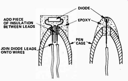
Fig. 2. This diagram shows how the sensor is mounted into a ball-point
pen casing or similar.
ADD PIECE OF INSULATION BETWEEN LEADS JOIN DIODE LEADS ONTO WIRES
------------------
HOW IT WORKS - ETI 130.
A forward biased diode has a temperature coefficient of about - 2 mV/0C. That is the normal voltage across a silicon diode of nominally 0.6 volts will decrease by two millivolts for every degree C increase in temperature. This change with temperature is sufficiently linear over the range of 0 to 1000C to use it as a temperature sensor.
What the ETI 130 circuit does is to amplify this voltage and to provide offset compensation for the normal 0.6 volt drop across the diode.
Transistors Q1 and Q2 provide a constant-current source of about 5 mA into the zener diode ZD1 such that a very stable five volt reference is obtained which is independent of the battery supply voltage. (V supply greater than 6 V.) The forward bias current through the sensor diode is about 0.5 mA as provided by R1. This current is low enough to prevent errors due to self heating of the sensor diode.
The voltage across the sensor diode is amplified by IC1 (a very high input- impedance operational amplifier) whose gain is fixed at the ratio of (R7 + RV2)/R4. The necessary offset is provided by RV1 which is adjusted to cancel the normal 0.6 volt drop across the diode. By selecting the correct values for R5 and R7 as shown on the circuit diagram the indication of temperature in degrees C or F may be obtained.
-------------------
PARTS LIST
R1,3
Resistor 10k 1 / 2 W 5%
R2 ,, 100 V2W 5% R4,6 '1 100k 1 / 2 W 5% R5,7 ., See Fig. 1 and test.
RV1 Potentiometer 10k * trim type RV2 t, 100k * "
*for digital readout a multiturn trim potentiometer is recommended.
C1 Capacitor 33pF ceramic C2,3 0.047uF polyester
D1 Diode 1N914 ZD2 Zener Diode BZX79C5V1
Q1,2 Transistor BC558, BC178 ICI Integrated Circuit LM308 Metal box Two 9v batteries Two pole toggle switch PC board ETI 130 3.5mm plug and socket Two pin plug and socket for output
-----------------
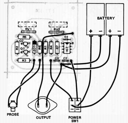
Fig. 3. Component overlay and interconnection diagram.
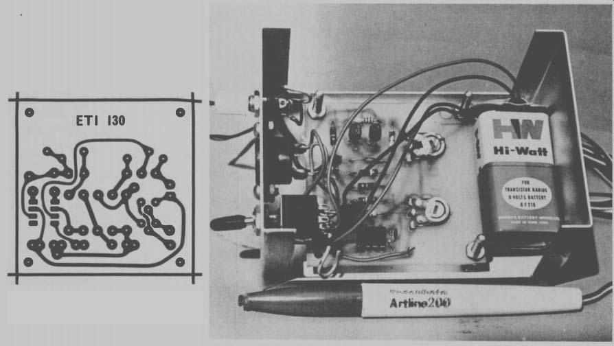
Fig. 4. Printed circuit pattern. Full size 63 x 63 mm. ------ Internal
view of the completed temperature converter. Note also the probe at front.
---------------