By JOHN T. BAILEY
Two simple rules for designing and servicing circuits in which diodes are used to drop voltages for series filament strings.

HERE is an increasing number of TV sets using a silicon diode rectifier instead of a power resistor to drop the voltage applied to the series-heater string to the required value. This diode application should not be confused with a similar application where the diode is in the circuit to supply a lower value standby current and is switched out of the circuit to provide essentially no warm-up delay. This article is devoted to the former voltage-dropping diode application. One may be surprised to learn of the problems encountered in designing and servicing such a simple circuit.
Fig. 1A shows a typical 150-mA heater-string circuit for a phono amplifier using a resistor to drop the line voltage to the value required for the sum of the individual heater voltages. Old timers will recall early a.c.- d.c. amplifiers and radios in which the dropping resistor was built into the line cord in order to keep heat dissipation out of the cabinet.
They will also recall worried customers who thought their sets had a short because the line cord would run quite hot.
And then a few do-it-yourself set owners were known to have cut off part of the line cord because it was too long for their needs. These perplexed souls couldn't understand how shortening a line cord could possibly affect the set's operation. Well, those days are gone forever. Line-dropping resistors, if needed, are now much smaller, dissipate less heat, and are mounted inside the sets. But in certain applications, a diode should be used instead of a dropping resistor because it costs less, is smaller, and runs cooler (passes either negative or positive half of input waveform, not both).
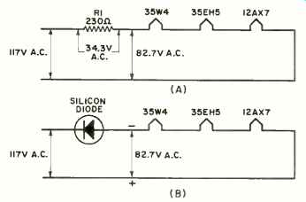
Fig. 1. Typical a.c: d.c. phono-amplifier heater string circuit using
(A) a dropping resistor and (B) a diode replacement for dropping input
line voltage to obtain the value required for the sum of the individual
heater voltages.
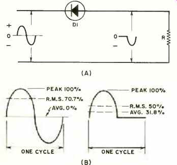
Fig. 2. (A) Input and output waveforms of a half-wave rectifier with
resistive load and (B) relationship of r.m.s. and average values to peak
values between one cycle of sine wave and the half-wave rectified voltage
across resistive load.
Design
Fig. 1B shows the same heater string but with the resistor replaced by a diode. One obvious question at this point is what happened to the 34-volt difference between the line voltage and the heater string? Where is it accounted for in the simple series circuit? The answer is that the diode passes only the positive or negative portion of the sine wave applied to the circuit. Which portion depends on whether it is connected as shown for a negative output or reversed for a positive output. As for heating the string, it makes little difference which way it is connected but there is a slight preference for the negative output connection. According to one major tube manufacturer, with the heaters negative with respect to cathodes at or near ground potential, the heater will not pick up electron emission from other parts of the tube.
Now it may be asked why isn't the voltage that is fed to the heater string just one-half of the line voltage since the diode passes one-half of the sine waveform? The answer is that, for heating purposes, we must deal in terms of r.m.s. (effective) currents. Regardless of the waveform, we must design the circuit for an r.m.s. current equal to whatever the current rating of the string. With the type tubes indicated in Figs. 1A and 1B, the tube handbook rating is 150 mA. Current ratings are understood to be r.m.s. values because heating effect is based on r.m.s. currents. Tube heaters are resistive. An r.m.s. voltage applied to a heater string will cause an r.m.s. current to flow. Therefore, we want to know what is the r.m.s. voltage output of the diode and why it is not one-half of the voltage applied to the diode by the line voltage.
Fig. 2A shows the waveform of a half-wave rectifier when the load is resistive. Disregarding the small drop across the rectifier, the peak value of the output waveform below the zero reference is equal to the peak value of the input waveform. Electrical engineering handbooks will show (see Fig. 2B) that the r.m.s. value of a sinewave waveform is 70.7% of the peak value and the r.m.s. value of a halfwave rectified waveform is 50% of its peak value. Hence, the r.m.s. current flowing through R of Fig. 2A is 70.7% of the r.m.s. current that would flow if D 1 were not in the circuit. In other words, the r.m.s. voltage applied to the heaters is 70.7% of that applied to the diode. Again, referring to Fig. 1B, the voltage applied to the heater string is equal to 117 volts times 0.707, or about 83 volts. Actually, it will be a fraction of a volt less after allowing for a small drop across D1.
Incidentally, when designing for use of a diode, the heater-string current does not enter into the calculations.
Merely select a diode with a current rating greater than the heater-string current by whatever safety factor is desired. A safety factor of two should be ample. The diode must also have an inverse voltage rating greater than the peak value of the input voltage multiplied by a safety factor. Good design practice calls for a small bypass capacitor across the diode as protection against line transients.
Servicing
So much for design. Now let's look at some puzzling conditions pertaining to servicing. If the voltage across the heater string of Fig. 1B is measured with a service meter, the reading may be anything from 117 volts to 0 volts depending on the type of meter used.
With a d.c. v.o.m. it will be about 52 volts, which is considerably less than the 83 volts expected. This apparent discrepancy is because most service instruments respond to average values rather than r.m.s. values, but are calibrated in r.m.s. values. The best way to measure the voltage across a rectifier heater string is to use a suitable d.c. range of a v.o.m. and then multiply the reading by 1.57. This factor is the ratio of the r.m.s. value (50 %) to the average value (31.8 %) of a half-wave rectified waveform, relative to the peak value or 50/31.8 = 1.57.
Now we have established two simple rules. First, in order to calculate the r.m.s. voltage applied to the heaters, multiply r.m.s. input voltage applied to diode by 0.707. Second, when measuring the r.m.s. voltage across a heater string, use a d.c. range of a v.o.m. and multiply the reading by 1.57.
Why not measure the heater-string voltage with an a.c. range of a v.o.m. or a v.t.v.m.? The a.c. circuitry of these instruments varies according to their manufacturer so multiplier values cannot be stated for all cases. They will all read the same on a sine-wave voltage because the scales are calibrated to read r.m.s. values even though a v.o.m. responds to average values and the v.t.v.m. to peak values. To illustrate variations found in meter readings, here are some actual voltage readings taken across the heater string shown in Fig. 1B. With a v.o.m. on the a.c. scale, the reading is 58 volts with a full-wave bridge circuit; 117 volts with a half wave bridge circuit or 0 with the leads reversed. With the v.o.m. on the d.c. scale, the reading is 52 volts with a resistor in series with the meter.
Using a v.t.v.m. and a differential amplifier meter circuit, the reading is also 52 volts. With a shunt diode and the v.t.v.m. on the a.c. scale, the reading is 80 volts or 37 volts with the leads reversed.
An a.c.- d.c. dynamometer reads 82 volts.
Phono-amplifier heater strings have been used as illustrations because they are relatively simple. Actually TV sets are where rectified heater strings are finding widest application. Color-TV tube sets have so many tubes that, where series heaters are used, more than one string is often required. Such an arrangement, using a diode for one of the strings, is shown in Fig. 3. When tubes and transistors are combined in a (hybrid) set, the tubes are relatively few, hence a diode to reduce the voltage to the sum of the heaters of a few tubes is a convenient solution. Such a circuit is shown in Fig. 4.
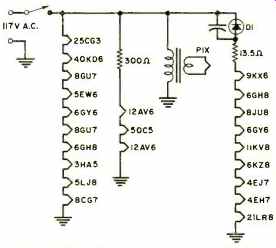
Fig. 3. Simplified heater string circuits in Silvertone color-TV
chassis 528.72500. Note the variety of series heater string circuits
that may be found in color-TV sets having a large complement of tubes.

Fig. 4. Simplified heater string circuit found in the RCA hybrid (tubes
and transistors) B & W chassis KCS169X series.