By ROY A. WALTON
------ Two switches are used to select the square-wave frequency
desired from a low 6 Hz all the way up to 60 kHz.
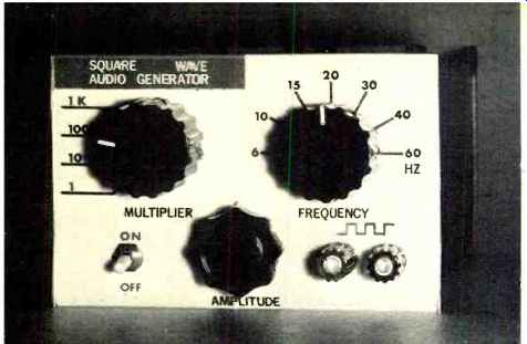
Inexpensive, accurate generator which will supply continuously variable output up to I V into an impedance as low as 8 ohms.
A SQUARE-WAVE generator is a highly versatile instrument and is useful in many tests from amplifier analysis to finding the length of a roll of coaxial cable. One that is known to be accurate has even more uses, such as serving to calibrate an oscilloscope time base or checking frequency-measuring devices.
The main drawback of a precision generator is the high cost. This article will detail the construction and calibration of a high-precision square-wave generator that cost the author less than $25.00 to build.
The specifications are as follows: frequency over the audio spectrum is 1% accurate, the range is 6 Hz to 60 kHz in four multiplied steps of seven increments (6, 10, 15, 20, 30, 40, and 60 Hz times 1, 10, 100, and 1000), and a common-emitter output stage will supply a continuously variable voltage of 1-volt peak-to-peak maximum to as little as an 8-ohm input.
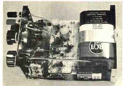
Above: With cover removed, here is what the generator looks like.
Circuit Operation
Q1 (Fig. 1) is a UJT operating as a relaxation oscillator with Si choosing the resistance through which the timing capacitor, selected by S2, is charged. This RC network determines frequency of the oscillator whose output is a sawtooth waveform coupled by C8 to the buffer, Q2. R9 sets the operating point of Q1 and acts as a master-oscillator adjustment for the entire frequency range. It may be used to offset effects of temperature extremes or weak batteries.
ICI is a JK flip-flop operating in the divide-by-two mode and is triggered by Q2. R13 is located in the inverted output lead of the IC and is used to adjust a feedback voltage that prevents spurious counts.
Q3 is a common-emitter stage with R14 controlling the output amplitude. This configuration allows the signal to be fed to fairly low impedance inputs as well as the high impedances usually encountered.
It should be noted that J1 is 6 volts positive with respect to ground. This is to aid in preventing adjacent-capacitance effect as is the chassis ground of negative battery terminals.
The only part of the design that might be considered difficult is obtaining the correct values for R2 through R7.
These are the resistors in the frequency switch and must be accurate almost to the ohm. This high accuracy is fairly easy to obtain by "trimming" the resistors; that is, a bundle of resistors is made up by paralleling two or more common values to come up with the exact value needed. These resistive values are found by using the generator in a partially completed state, the 60-Hz power-line frequency, and an oscilloscope. The procedure will be detailed later.
It is recommended that component placement closely approximate that of the prototype, as shown in the photographs. The following parts are mounted on the circuit board: R8, R10, R11, R12, R13, R15, R16, C8, C9, C10, Q1, Q2, Q3, and ICI. Si (Frequency), S2 (Multiplier), S3 (On-Off), and R14 (Amplitude) are mounted on the front panel. R9 was mounted on the cabinet top in the prototype and adjusted through an access hole. This control provides a semi-permanent adjustment and should be located so adjustments can be made without opening the cabinet. All components should be mounted and soldered except R2 through R7.
Calibration and Alignment
Couple the generator output directly to an oscilloscope vertical input. Set the generator controls to SI 60, S2 Xl, R9 midrange, R13 midrange, and R14 to maximum. The scope display should be a square wave. Connect a 60-Hz power-line source to the scope horizontal input and use this as the sweep. The display will be a rotating rectangular figure and R9 should be adjusted so that the figure is stationary. This setup should be returned to frequently during calibration to correct for any possible drift in the instrument frequency. Return the scope to internal sweep and adjust the sweep controls for exactly 12 cycles of the generator's 60-Hz waveform.
Resistor R2 will be a bundle of resistors referred to as R2a, R2b, etc. Choose R2a to have a slightly higher value than R2 (see Table 1) and tack-solder it to its position (40 Hz) on S1. When R2 is correctly trimmed the display will be exactly 8 cycles. If more than 8 cycles are displayed, R2 is low in value or if fewer than 8 cycles are displayed, R2 is high. If 8 cycles cannot be produced by a single resistor, R2a is chosen for a display of slightly less than this amount and trimmed with higher value resistors until the correct display is obtained. This is done by soldering R2a in the circuit and manually bridging it with other resistors until the right display is observed. If the correct display is still unobtainable, R2b is chosen to give as close to the right display as possible yet still yielding less than 8 cycles. R2b is soldered in the circuit and R2c is found using the same method, as is R2d if necessary. (The prototype never required more than four resistors to a bundle.) This calibration should be checked against the 60-Hz power-line frequency on the scope horizontal input as was the 60-Hz square wave. In this instance a complex figure will be observed that, ideally, will be stationary, although if it is rotating slowly it is acceptable. If the figure on the oscilloscope is rotating rapidly, the R2 bundle needs additional trimming.
It is helpful to swab the resistors and switch lugs with alcohol after soldering as the resistance changes temporarily with heat and can shift the frequency of the oscillator.
This same procedure is used to calibrate the remainder of the resistors on Sl. Maintain the scope internal sweep to show 12 cycles of the 60-Hz output. This should be checked frequently and readjusted to compensate for any drift in the scope. The correct displays are as follows: 40, 8 cycles; 30, 6 cycles; 20, 4 cycles; 15, 3 cycles; and 10, 2 cycles. To calibrate the 6-Hz position of Si the scope must be reset to display 10 cycles of the 60-Hz generator output and R7 trimmed to produce a 1-cycle display. Adjust R13 for a stable output of the 6-Hz display. Unless the scope used is d.c.-coupled, distortion will be evident at the low-frequency settings of the generator.
The last step is to calibrate the multiplier capacitors. This is done in a similar fashion to the frequency switch except that the main capacitors must merely be brought into the range of the trimmers. Adjust the scope for a display of one cycle of the generator 60-Hz output. Set S2 to X10 and adjust C2 for 10 cycles of display. If this is not within the range of C2, C3 must be trimmed as were the Si resistors until it is. (The more capacitance the fewer cycles displayed.) The final adjustment of C2 should be made, with the cabinet closed, using a non-conducting alignment tool. This should be done while observing the figure produced by the 60-Hz line frequency on the scope horizontal input. Adjust C2 for a stationary figure. (The shape of the figures used is of no importance in this alignment, only the lack of rotation.) The remaining two ranges of this switch are calibrated in the same manner by setting the scope for a display of 1 cycle of the previously calibrated range and adjusting the following range for 10 cycles of display. Since the frequencies overlap, the same frequency may be observed on two different settings of the multiplier switch.
This generator is quite stable and the accuracy will remain within 1% under normal operating conditions. If temperature extremes or weak batteries are encountered, R9 can be used to compensate for them. The generator should be checked periodically by feeding its 60-Hz X1 output to the scope vertical input and the power-line frequency to the scope horizontal input and adjusting R9 for a stationary rectangular display.
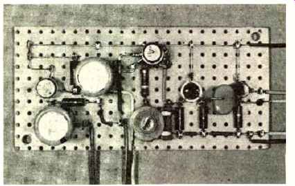
-------Close-up of circuit board showing transistors and the IC.
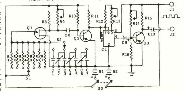
Fig.1. The schematic shows the unijunction relaxation oscillator feeding
a buffer amplifier whose output is divided by 2 in an integrated circuit.
The output stage provides the isolation. All parts are standard and available.
R1-4700 ohm, 1/2 W res.
R2, R3, R4, R5, R6, R7-See text* R8-1 000 ohm, 'A W res.
R9-5000 ohm pot (Master Osc. Adjust.)
R10, R11-5600 ohm, 1/2 W res. ± 5%
R12-390 ohm, 1/2 W res.
R13-1000 ohm pot (Feedback Adjust.)
R14-10,000 ohm pot (Output Amplitude)
R15-750 ohm, 1/2 W res. ±5%
R16-10,000 ohm, % W res. ±10%
All resistors should be carbon, do not use wire-wounds.
C1-1 p.F, 50 V capacitor C2, C4, C6- Trimmer or padder in anywhere near 100 to 800 pF C3, C8-0.1 µF, 50 V (min.) capacitor C5-0.01 µF, 50 V (min.) capacitor C7-0.001 µF, 50 V (min.) capacitor C9, C1 0-500 µF, 15 V elec. capacitor S1-S.p. 11-pos (use 7 pos.) switch (Frequency)
S2-D.p. 5-pos. (use s.p. 4 pos.) switch (Multiplier)
S3- D.p.s.t. switch (On-Off)
J1, J2-5 way binding post
B1-9-volt transistor battery
B2-6-volt lantern battery
Q1- Unijunction transistor (HEP 31 0)
Q2-GE 10 (or HEP 55) transistor
Q3-2N404 transistor (or HEP 739)
IC1-JK flip-flop (HEP 558)
*Resistors R2 through R7 were from the parts box or selected from 1/2-W resistor "grab bag."
================
Table 1. Values of resistors used for R1 through R7, respectively.
MEASURED RESISTANCE
R1 (4.8k)
R2 (7.2k)
R3 (9.7k)
R4 (12k)
R5 (19k)
R6 (28k)
R7 (48k)
RESISTORS USED (in order of insertion)
4.7 k 8.2k, 15k, 220k, 10k, 100k 15k, 330k, 1.5M 20k, 580k, 6.8M 30k, 680k, 1.5M 47k 820k
It should be noted that the resistors used were from a "grab-bag" and many had no tolerance band. This is the reason that calculated resistance for the ones actually used may not be the same as the measured resistance.
================