By FOREST H. BELT /contributing Editor
Some of the new antennas just have new names, but others have real design improvements. Here's what is available to help you choose the best antenna for your particular area. Complete listing of recommended antennas is included.

SNOW-FREE television pictures, with all colors in place, are the stakes in the antenna game. Sometimes the game is played with numbers, like how many decibels of gain one antenna has over another. Or the ammunition may include technical-sounding phrases like "front-to-back ratio," "side lobes," or some such. Boxes may display a number of very enticing catch-labels; such as, "Color Spectrum," "Magic Color," "Color Guard," "Color Tuned," "Color Brite," "Sensar," and so on.
But whatever the words or numbers, the crucial question is, "Does this antenna give a good color or black-and-white picture where I live ?" You figure the topography around you, the distance and power of the stations, and how high you can mount the antenna. Then you choose.
The full-page table with this article is a general guide. If there are no u.h.f. stations, you don't need an all-channel model. If u.h.f. is the only kind of TV you get, you won't need an antenna for v.h.f. too. Of course, if there's distant v.h.f. to be picked up by a very sensitive antenna mounted high, you might want to consider an all-channel model. Or, a v.h.f. or u.h.f. station might be coming to town soon.
Table 1 gives an idea of mileages. If terrain is hilly, consider the next greater distance grouping; it'll take a more sensitive antenna model to pull signals "over the hills." It's the same if you live between two mileage categories; again pick the more sensitive antenna. Beyond the mileages shown, even the best antenna is likely to produce only a snowy picture unless mounted extremely high or the terrain is very smooth.
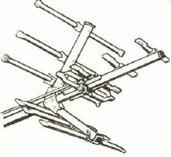
Fig.1. Winegard-developed u.h.f. antenna section. It fits in front of v.h.f.
antennas made by other manufacturers as well.
-------------------
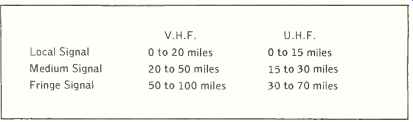
Table 1. Approximate distances from transmitting antenna for local, medium.
and fringe signals (see full-page chart).
---------------
As for which brand, you'll have to choose for yourself.
The big chart lists the model each major manufacturer recommends for each category. Prices are not always a reliable guide to what's "better." Ask your antenna distributor to let you see the antenna. Judge solidity of construction, ease of assembling and erecting, and weatherproofing, along with price, directional quality, and gain (sensitivity).
Some manufacturers explained their designs to us. The shapes of these high-gain monsters, however odd they may appear, are not the least bit accidental. The reasoning behind some of them may interest you.
------------------------
Table (right) shows antennas recommended by various antenna manufacturers for different signal areas. All antennas are outdoor types. Each manufacturer has been limited to a single choice; in many cases, there are other antennas in company's line with somewhat different gains and directivities. Most of the antennas are general-purpose types where no special installation or interference problems exist. For approximate mileage distances for local, medium, and fringe signals, refer to Table 1. It is frequently possible to combine a v.h.f. antenna with a separate u.h.f. antenna using a splitter and /or stacking bars. Such arrangements have not been listed. Most of these antennas, although mainly designed for color or black and white reception, can also be used for FM reception too.
-------------------------
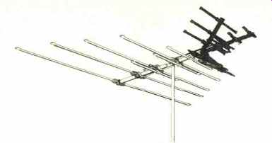
Fig. 2. "Impedance correlators" (short elements under dipoles)
are a feature of this Antenna Corporation of America model. The u.h.f. section
in front is shown solid in the illustration.
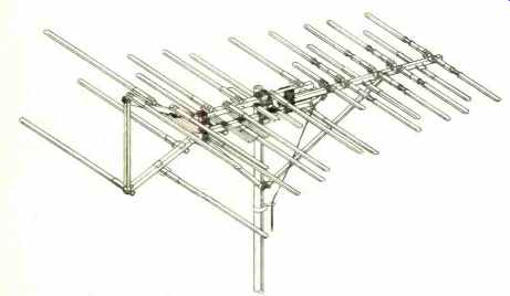
Fig. 3. Finco antenna features delta reflector, transposed feeder bars,
and directors that use insulating gaps shown.
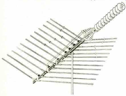
Fig. 4. A distinctive feature of JFD log-periodic antenna is the set of
half-disc reflectors for high u.h.f. gain.
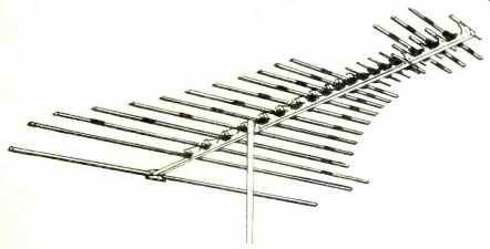
Fig. 5. Lengths of the elements in this GC Audiotex antenna follow exponential
formula, said to give good broadbanding.
U and V Together
For example, Winegard has a patented u.h.f. design (Fig. 1) using what are called "tetrapole collector elements." Only one element is driven-the folded dipole that appears to wrap around the boom. Lead-in fastens at the bottom.
You'd expect the folded dipole to be solid across the top, but it's not. It has a center gap, just like at the bottom. Of course, that gap has to be closed electrically for the dipole to present a 300-ohm impedance at the lead-in block on the bottom. A pair of phasing bars (you can only see one in the illustration) are connected at the top. They run parallel to the boom. They are just the right length at u.h.f. to present a zero impedance--effectively a short circuit--across the tap on top of the dipole.
Why bother, you ask? At v.h.f., the phasing bars and the u.h.f. dipole have no resonance. The 300-ohm v.h.f. antenna feeds directly to the phasing bars. They and the u.h.f. dipole are mere coupling lines to the lead-in block. The lead-in sees 300 ohms for either antenna.
The u.h.f. part of one Antenna Corp. of America model uses this Winegard design. Behind it, the v.h.f. sections looks simple (Fig. 2). There are two dipole driven elements (nearest the mast), two reflectors (back end), and one straight director. The V- shaped array that is a corner reflector for u.h.f. is also a director for v.h.f.
Elements with this straight design work in two modes.
Their entire lengths resonate at a half-wavelength for low band v.h.f. For high-band v.h.f. they divide into thirds and resonate at three half-wavelengths.
That high-band "breakup" can be uneven and upset impedance at the take-off point in the center. The result could be serious dips and lobes in the response of the antenna. To counteract that, short elements are added just beneath the longer driven dipoles. They're called "impedance correlators," and they smooth out response of the array. An even 300 ohms for all channels is presented to the lead-in.
Shaping and Spacing the Elements
The Finco (Finney Co.) antenna in Fig. 3 has several design features of special interest. One is a patented formula the company calls its "frequency-dependent principle" (FDP). The object is to raise the gain of the antenna as frequency goes up to compensate for natural losses in the TV spectrum. Shorter (higher-frequency) elements toward the front are spaced farther apart along the boom.
Feed-centers of the dipoles are transposed, a practice that narrows the front lobe of the antenna response. The second special feature is how they're transposed. Instead of the driven dipoles being straight across and separated at the center, these are staggered along two electrically separate booms. One half of any given dipole is on one boom, the other half on the other. The effect is electrical transposition along the length of the booms. One boom then goes to one side of the lead-in terminal block, and the other boom to the other side.
A third feature is called the "delta reflector." It purports to give better front-to-back ratio than plain reflector bars.
The stagger principle of mounting element halves continues in the delta, as you can see. The delta connects electrically to the back ends of the double boom. The result is a closed resonant loop that is said to smooth response across the v.h.f. band.
The fourth noteworthy design factor in this model is in the director elements up front. To aid in breakup into three half-wave elements, so high-band "cells" form along the driven elements, the directors are divided by insulators.
The technique, used by other manufacturers too, helps improve high-band performance of this particular antenna.
Gavin Industries' antennas use what is called "yagi spacing" for elements; they're all the same distance apart.
Lengths vary across the low v.h.f. band, for a broadband effect. As usual, the elements operate in thirds for high band v.h.f.
Yagi-type antennas can produce undesirable side lobes at high-band frequencies, which also detract from gain. The rear two reflectors on Gavin antennas are swept a bit forward to eliminate side lobes. This also narrows and strengthens the front lobe. Directors are short, to bring high-band gain up to match low-band.
Log-Periodic Antennas
The log-periodic principle for antenna elements was pioneered by JFD Electronics. The design formula expresses a logarithmic relationship between velocity of television signals and the size and spacing of elements. One result is better gain as frequency goes higher, and with smooth impedance coupling.
An all-channel version is pictured in Fig. 4. The v.h.f. section uses some techniques already described. The twin boom method of terminating the driven elements is one; it transposes without criss-crossing wires. Breaking up the front elements with insulators has already been described.
But the insulators in JFD models are capacitive, "tuning" the dipoles for efficient capture of high-band signals. Other manufacturers use "bat-wing" tuning stubs which are mounted at an angle from the antenna elements for this same purpose.
Look at that unique u.h.f. array up front. There are two driven sections, each stamped out of one metal plate. Spacing and lengths of these elements are log-periodic, in the u.h.f. band. The wedge shape, tapering together at the high-frequency ends, purportedly improves capture of u.h.f. signals.
The half-discs are u.h.f. directors. They're very broadband. JFD calculates they deliver twice the gain of linear directors.
A line of antennas from GC Electronics, marketed under the Audiotex brand name, is partly log-periodic. An all-channel version appears in Fig. 5. Note the curved pattern outlined by the lengths of the elements. This is one application of the logarithmic design formula. According to designers, this special tapering improves the broadband response of the antenna.
These dipoles are broken up by insulators, too, but not into thirds. The short outer stubs make parts of the driven elements parasitic for some of the other elements. Gain and smoothness of response over the bands is the purpose. The dipole-to-dipole wiring harness, which is hard to see in the illustration, is a standard transposed type; it has small insulated copper wire instead of the usual heavy bare aluminum wire.
-----------------------
------- After this article was written, we learned that JFD Electronics
was just getting ready to introduce a very unusual all-channel outdoor-indoor
antenna called "Stellar 2001." We don' have too many technical
details as yet, but here are some things we have been able to find out about
it. The antenna consists of a multi-element linear dipole array with built-in
v.h.f. solid-state amplifier that is said to provide enough signal to drive
two to four receivers. The antenna and amp are en closed in a sealed weatherproof
fiber-glass housing. The assembly is very compact, measuring only about
34" X 28" X 4" thick. Coax output from the built-in amplifier,
whose circuitry is etched from a single sheet of copper that may also be
used for the antenna elements, is fed to an associated power supply /2-set
coupler. A pair of 300-ohm outputs are then connected to two TV receivers.
The manufacturer claims a range of up to 70 miles for the new antenna, depending
on signal strength.
Interestingly, the antenna can either be mast-mounted or it can be mounted directly using the three small mounting brackets supplied. With these brackets, the antenna is placed several inches above the roof, above the attic floor, below the attic rafters, or even below the ceiling of a room.- Editor
-----------------------
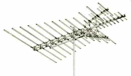
Fig. 6. You can recognize this Jerrold antenna by the circular insulators.
Wires inside form transposing harness.
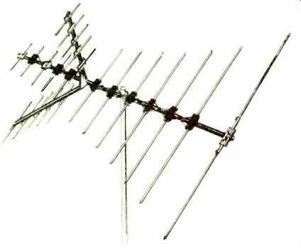
Fig. 7. The u.h.f. portion of the RMS Electronics antenna is miniature
version of v.h.f. plus use of corner reflector.
It's also noteworthy that the u.h.f. array is sandwiched between the main v.h.f. array and some high-band directors at the extreme front. The directors are also broken up by insulators into parasitic elements for the u.h.f. band. This is another case of multiple use of elements for higher gain and for a smoother over-all response.
Multiple Features
For a collection of unique features, consider the new "VU- Finder" from Jerrold Electronics Corp. Fig. 6 illustrates one model of this high-gain all-channel antenna.
The elements are spaced evenly, yagi-style. Their lengths taper linearly toward the front. Transposed wiring is used, but it's through disc-shaped insulators with imbedded conductors. This trick lets two straight wires harness together the active elements. All the dipoles along the main boom are driven, for high gain. But shorter elements act as directors for longer ones and longer ones act as reflectors for the shorter ones.
Up front, you can see a couple of short parasitic elements that help break up the long elements for high-band v.h.f. signals. But even more effective are the parasitic elements that appear to be part of the u.h.f. array. They, too, are for high-band v.h.f.
The only driven u.h.f. element is the specially shaped bow-tie you see in the middle of the u.h.f. array. Its shape is a patented design developed by Jerrold.
It's called an extended-resonance u.h.f. dipole. The projections at each corner are angle-aluminum, and the bow-tie itself is not flat-it's molded with half-cylinder depressions toward the sides.
The very shortest parasitic elements arrayed on the two angled booms form a corner reflector that improves u.h.f. sensitivity. The high-band v.h.f. elements contribute to u.h.f. gain, too; they "break-up" into thirds for u.h.f.
Finally, to raise u.h.f. gain even more and to concentrate forward directivity, there's a boomful of parasitic u.h.f. elements at the very front of the antenna.
You'll recognize some design characteristics of the RMS Electronics' antenna in Fig. 7. The chief difference is that its driven u.h.f. array is practically a miniature replica of its v.h.f. array-- even to the transposed element-phasing harness. There's a corner reflector for u.h.f., and one director; the v.h.f. array has only one reflector, and it's linear. The sketch shows a suburban model; higher-gain models have more u.h.f. directors and more v.h.f. reflectors.
Another feature is the coupling bracket between the v.h.f. and u.h.f. sections; it's jointed. You can point the u.h.f. antenna as much as 45 degrees to one side, in case the u.h.f. stations are not in the same direction as v.h.f.
Indoor /Outdoor Types
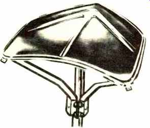
One of the most unusual new antennas is the Wtnegard Sensar (shown at top left of cover). There's only one driven element. It's a big flat dipole.
Each half of the dipole is about 2 1/2 feet long and 6 inches wide, stamped out of flat aluminum. A slot is punched right down the middle of each flat plate, for most of its length. The tips are turned downward, giving the whole thing a wing-like appearance.
The center ends of the dipole halves fit into a molded plastic housing. In the more sensitive model, a transistor amplifier boosts the signal several dB before feeding it into the 75-ohm coaxial downlead. (Power for the amp comes up the lead from a power supply /2-set 300-ohm coupler; a small lamp on the plastic housing lights when power is applied )
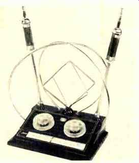
Fig 8. One dial on this JFD indoor antenna switches the elements to rid
picture of ghosts; the other dial is employed for overall tuning purposes.
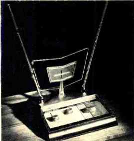
Fig. 9. Channel Master's indoor model has powered transistor amplifier.
Knobs are for reducing ghosts and interference. and performing tuning.
The Sensor is for indoor or outdoor use. Winegard claims an operating radius of 40 miles or more when driving two receivers, if the amplified version is used. If ghosts are a severe problem, the Sensar can't do much about them-particularly if they're off the back end. It's an all-channel antenna, but u.h.f. performance of our sample was not as good as for v.h.f. Small size makes it a natural for attic or suburban rooftop installation, and a special bracket mounts it conveniently on the side of a camping trailer or pickup-truck camper.
There are also a multiplicity of indoor antennas. Indoor antennas have progressed far beyond the old "rabbit- ear" days. The simplest have telescoping dipoles for v.h.f. and a circular loop for u.h.f. That's okay for 10-15 miles from the station. Careful orientation takes care of most ghosts: Yet there are some fancy indoor units. Gavin has a model with two u.h.f. loops, one slightly smaller to cover the higher u.h.f. channels. Some models have a "tuning" knob. The television viewer uses it to adjust the dipoles electrically for the exact channel.
JFD Electronics makes the complex indoor antenna shown in Fig. 8. One knob switches elements for various ghost conditions. The telescoping dipoles have loading coils, so they resonate for low-band v.h.f. at less cumbersome lengths. Another knob tunes inductive-capacitive circuits inside the base.
Channel Master has an amplified indoor antenna (Fig. 9) called the "Chroma 1." It has telescoping dipoles for v.h.f. The u.h.f. antenna is a trapezoid-shaped wire loop, inside of which is a small metal plate of the same shape. Its v.h.f. transistor amplifier feeds a 75-ohm coaxial cable. The u.h.f./v.h.f. splitter converts impedance to 300 ohms at the receiver end of the cable.
The base has three controls to rotate u.h.f. antenna, switch from u.h.f. to v.h.f., and tune an antenna-matching circuit for best performance and minimum nearby-station interference at other frequencies.