By ED BRENNER, /Director of Engineering Lambda Electronics Corp.
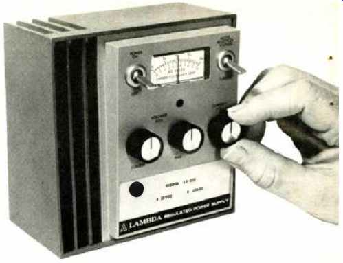
------- Lambda Model LL-902 bench-type IC regulated laboratory power
supply which provides an adjustable d.c. voltage range of 0-20 volts
at currents from 0 to 0.65 ampere.
The capacitor-filtered, series-regulated supply is the most common. Final decision as to characteristics is usually trade-off between performance and price.
POWER supplies and power regulators are represented by a wide assortment of devices ranging from batteries and generators to dynamic electronic units using feedback circuits.
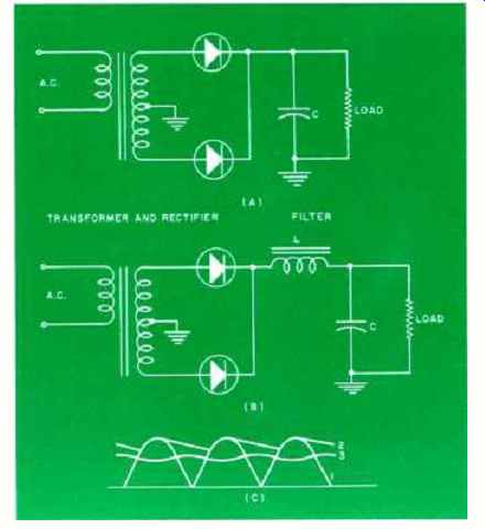
Fig. 1. Rectifier and filter configurations showing (A) capacitor and
(B) LC filters. (C) D.c. output voltage waveforms for single-phase, full-wave
rectifier with (1) no filter, (2) capacitive filter, and (3) an LC filter.
The specific function of the a.c.-to-d.c. power supply is to provide d.c. voltage and current from a primary a.c. source.
The electrical characteristics of the power supply and the physical form it takes must be a function of the circuitry being powered and the physical requirements of the system in which the circuitry is used.
Circuits and Characteristics
Power conversion generally starts with rectification, i.e., converting a.c. input voltage to a d.c. voltage. Because the output of a rectifier contains a relatively large a.c. ripple component in addition to its d.c. value, a filter must be used to attenuate the ripple component before this d.c. voltage is applied to a d.c. load. Figs. 1A and 1B show two types of unregulated power supplies while Fig. 1C shows the output ripple.
The amount of ripple present after filtering the rectified output is a function of the circuit components and the load current. In actual practice, at full-rated load, the capacitor-input filter supply is limited to approximately 5% r.m.s. ripple voltage while the LC input filter supply attains 1% r.m.s. ripple voltage. Of course, better filtering can be had by using components larger than those dictated by economics or package volume when compared to the size of the transformer. However, such filtering can better be accomplished using other means.
With the unregulated power supply, no matter how efficiently ripple is reduced, the rectified-filtered d.c. output can change substantially with load current and /or powerline variations. Typical regulation characteristics include: For capacitor-input filter supply: line regulation of 1.2% per % line change at full load, and load regulation of 20% from '/y load to full load. For LC-input filter supply: line regulation is 1% per % line change at full load, and load regulation is 10% from '/p load to full load.
Because of these relatively poor performance specifications, unregulated supplies find limited application and are generally only used to power lamps and electromechanical devices where poor regulation is acceptable. They find greater use as front-ends for regulated power supplies or as d.c. power distribution sources in systems where d.c.-to-d.c. point-of-load regulators are employed.
It is only recently that the unregulated supply has been readily available as an off-the-shelf item. Lambda has made available, as stock items, a line of power kits containing components selected for a predesigned power-supply circuit so that a purchaser could build his own d.c. power supply. The kit components vary depending on circuits selected as well as the d.c. voltage and d.c. current required.
Major components supplied are transformers, filter chokes, computer-grade electrolytics, silicon rectifiers, and a power hybrid voltage regulator when a regulated output is required.
The Ferroresonant Transformer
The ferroresonant transformer is an effective means of compensating for poor line regulation. The capacitor-input filter supply can be transformed into an improved regulated supply by replacing the linear input transformer with a ferroresonant transformer which provides regulated a.c. to the rectifier-filter section and improves ripple attenuation by squaring the sine wave. Line regulation and ripple waveform change are caused by the resonance set up between a transformer winding and an external a.c. capacitor. See Fig. 2.
The ferroresonant transformer, inherently a current-limiting device, provides automatic protection against overload. Because its major drawback is sensitivity to line frequency changes, it is used only where line-frequency stability is assured. A typical ferroresonant power-supply specification includes: line regulation of 2% for line changes from 105 to 132 volts a.c. or 132 volts a.c. to 105 volts a.c. for any load between 25% and 100% of full load; load regulation of 5% from 1/2 load to full load; frequency regulation of 2.4% for each cycle change in line frequency; and ripple of 1% r.m.s.
The simple ferroresonant power supply is the most reliable regulated power supply in use today. Prerequisites for its use are: fixed input frequency, small load variations, and a tolerance for slow response to transients. A ferroresonant supply requires many cycles of input frequency to recover from any line transient.
Feedback-Controlled Regulation
The demand for better regulation imposed by today's sophisticated circuits and complex electronics systems is best met by the feedback-controlled power supply. This type of regulated power supply is capable of maintaining a substantially constant output voltage at a selected value, even though changes occur in the a.c. input voltage (within specified limits) and /or in the rated d.c. load current. In addition, these power sources can be made short-circuit-proof, preventing damage to the supply caused by load fault and can be made load-protecting by using overvoltage protectors to prevent load damage caused by internal supply failure. Fig. 3 is a general block diagram of the feedback-controlled regulated power supply.
There are many circuits which can be used to meet the requirements of the feedback-controlled power supply.
The approach selected is determined by economics, performance requirements, power output needs, efficiency, and specified input /output voltage levels.
The circuit with the widest application is the linear or series-regulated power supply, which is used most often where output voltages are below 100 volts and power output is below 500 watts. Refer to Fig. 4.
In this example, a.c.- to- d.c. conversion is accomplished by using a full-wave rectifier and a capacitor-input filter circuit. The control element is one power transistor or many transistors in parallel, as required, which absorbs the difference between the desired output voltage and the unregulated d.c. input. Because the series-pass element must handle the full-load current while maintaining relatively high voltage between input and output, it is basically a low-efficiency circuit. But since it is a linear circuit it has the potential for the best general specifications. No other practical circuit has as fast a response, possesses the regulation specifications, as low a ripple, or is as versatile in application as the series-regulated power circuit.
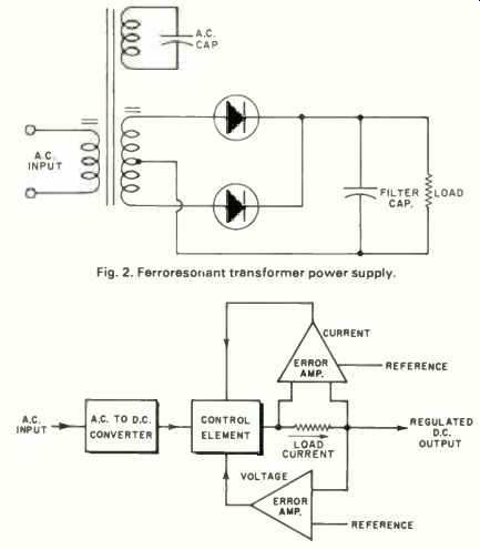
(top) Fig. 2. Ferroresonant transformer power supply.
(above) Fig. 3. Regulated power supply using feedback control.
Circuits with higher efficiency are usually obtained by switching techniques, a circuit that produces pulses of current when the control element is in a saturated state or when the control element is at cut-off and absorbing maximum voltage and no current flows. The pulse width or repetition rate determines the output voltage and a filter section is required to transform the pulses of energy to d.c. The control element in this type of circuit is usually an SCR (for low-frequency switching, high-power applications) or transistor (medium-power, high-frequency switching). The resultant circuit is a high-efficiency package with poorer regulation, ripple, and transient response than a series regulator but more watts per unit volume and lower cost per watt.
As seen from the preceding categories, the selection of a power supply is a study in economics and specification trade-offs with no single approach having an advantage for all applications. By studying some typical application requirements, a better understanding of power-supply technology and selection can be obtained.
Power-Supply Applications Laboratory Supplies: The use of supplies for a laboratory can be broken down into two categories, 1. standards and calibration, and 2. experimentation and breadboarding.
When a d.c. power supply is used as a voltage standard or a transfer standard for calibration purposes, its specs must be an order of magnitude better than average laboratory measuring equipment and include a means of setting up output conditions accurately. Almost all lab supplies are series-regulator types because of their superior performance characteristics. By using aged reference elements and high-quality resistors, voltages with accuracies of better than 0.01% can be obtained. By housing temperature-sensitive circuitry in a proportional-control oven within the supply, temperature coefficients better than 0.001 % / °C are obtained which virtually eliminate output changes caused by changes in ambient temperature. Circuit design and shielding techniques allow ripple to be below 100 p.V peak-to-peak thereby approaching an almost perfect d.c. signal.
The aged components and the oven insure a stability an order of magnitude better than the accuracy. Decade switches can be used to set up output conditions so that resolution down to the microvolt range is obtained. If the calibrator is to be part of an automatic test rack, its output voltage must be capable of being programmed from an external source, such as a resistor network or a digitally coded signal. In the latter case, an accurate digital-to-analog converter is required to transform the digital command into either a programming resistor or analog voltage, depending on the accuracy required. In most applications, this type of supply is programmed by either a resistor or a programming voltage. In all cases, of course, the dynamic voltage standard must not be affected by load conditions or overloads, hence current limiting is a necessity and a line /load regulation specification of 0.0005% is required.
As a general lab tool, the power supply must be versatile, reliable, and rugged. Most lab supplies are capable of constant-voltage operation, constant-current operation, of being remotely programmed by either resistance or voltage, or series or parallel operation with similar supplies for expanded capabilities, and are completely protected against load fault. Voltage regulation for line or load is usually around 0.01% with ripple and noise approximately 1 mV peak-to-peak.
Meters are a "must" on lab supplies so that conditions of experiments can be monitored. Because these supplies are constantly handled, heat sinks should be inaccessible or, if exposed, electrically isolated and thermally cool to the touch. Power supplies, dissipative by nature, must have reliable cooling. For this reason fans should be eliminated in favor of convection cooling because fans and their associated filters represent a weak-link maintenance problem.
System Supplies: The power-supply user, faced with the problem of putting together a complicated electronic system, has a difficult job selecting not only the regulation technique to be used but also the method of power distribution. An electronic system normally needs a number of voltages to power a variety of circuits. Irrespective of the types of power supplies used, power can be distributed using various methods, e.g., 1. individual power modules for each voltage required; 2. a multi-output power supply where all power required for a system is derived from a single package; 3. unregulated d.c. voltage or coarsely regulated voltage distributed to point-of-load regulators where power is regulated at the point of final usage; and 4. a combination of all or some of the above.
Selecting the individual module is an attractive approach because almost any rating is available as a standard product from the power-supply manufacturer. This insures reliability because standard products from a reliable vendor usually have a performance record that can be verified and can be counted on for mechanical stability and production reproducibility. Moreover, the individual module requires simpler maintenance and fewer spare parts provisioning. Most power-supply manufacturers will assemble standard individual modules into a complete system power supply.
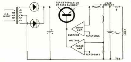
Fig. 4. Simplified schematic of the series-regulated power supply.
Multiple-output power supplies, usually less expensive than individual modules when volume production quantities are involved, normally lead to custom design, which has drawbacks. In addition to the initial circuit design phase, power-supply design also includes mechanical packaging design, thermal performance evaluation, and printed-circuit board layout design. Consequently custom design, where quick delivery is required, usually yields poor mechanical and thermal design, with resultant poor reliability.
If, however, series regulators are used, power hybrid regulators, with known electrical and thermal properties, can be used to reduce design time. By using a number of hybrid regulators in a standard mechanical package with known thermal properties, packaging design is greatly simplified, the printed-circuit board is eliminated, and more time can be spent on testing to assure greater reliability of the multi-output power supply. Although this approach does not guarantee instant availability, it eliminates many of the disadvantages inherent in the custom-design approach.
When system noise and power-line degeneration results in power distribution problems, the point-of-load regulator is used. In this application a highly efficient power source such as an unregulated supply, a ferroresonant regulator, or a coarsely regulated SCR supply delivers d.c. power to remote sites within the system. Regulation and fine filtering is accomplished at various circuit locations, eliminating crosstalk and noise injection between different sections of the system. The d.c.- to-d.c. type point-of-load regulators can be hybrid, monolithic, or discrete circuits mounted on printed-circuit boards or some other local assemblies where the regulated power is required. Here, again, the hybrid approach has the advantage because it provides the greatest amount of power (up to 5 amps) with a minimum of design time.
Present monolithic regulators are not practicable above 200 mA. In most very large electronic systems, it is not uncommon to find combinations of approaches used to satisfy the power distribution needs of the system.
It becomes evident, then, without even raising the question of regulation techniques, that the formidable problems confronting the system designer in the areas of power distribution are staggering. Factors involving economics, availability, maintenance, reliability, and signal conditioning must all be considered and a decision made.
Another factor not previously mentioned is: 3-phase vs single-phase power input to reduce copper requirements and power-supply skin temperature and their effects on associated circuitry. Because system power supplies are not accessible from exterior positions, they are normally designed with surface temperatures exceeding 100°C. Judgment must be used in power-supply placement to ensure proper cooling and prevent system circuitry temperature rise.
Data-Processing Equipment: All foregoing problems related to system power supplies are equally applicable to data-processing equipment. Because this type of equipment is commonplace in non-industrial environments, it is increasingly coming under the jurisdiction of Underwriters' Laboratories. Thus, it can he assumed that any power supply used in data processing must have or be capable of obtaining UL approval.
Modern data-processing equipment, because of its increased use of LSI (Large-Scale Integration), requires large concentrations of power in relation to equipment size. Because digital circuits do not require very finely regulated power sources, high-efficiency regulation techniques can be used. Generally, power supplies in these applications should have a combined performance bandwidth (line, load, ripple, and temperature) of better than 1 or 2 %. In some applications, however, ferroresonant power supplies are acceptable, where combined performance bandwidths of better than 10% are compatible with requirements.
Memory Systems: Memory systems are a particular problem because the preservation of data is of prime importance and a specific requirement. In order to ensure that no data is lost, power supplies must be sequenced "on" and "off" in a prescribed order. In the event of a.c. input power-line failure, d.c. power must be kept available for anywhere from 1 to 20 ms so that the system can permanently store the data before d.c. power is lost. Some means of detecting the loss of prime power must be provided. The same requirement also results in the need for undervoltage and overvoltage sensing circuits so that power-supply malfunction can be detected and the data stored before the power supplies fault to an out-of-limit condition.
In core-memory systems, the power-supply voltage must be varied with ambient temperature to assure proper functioning of the magnetic memory material. This is accomplished by programming the power supply with a thermistor network located at the core memory site.
Analog Circuits: The most widely used analog circuit is the operational amplifier. Its power requirements are normally a plus and a minus voltage of equal magnitude ( ±12 to 15 volts being the most popular range). In analog circuits the accuracy of the signal being processed is of the utmost importance. In order to keep power-supply fluctuations from affecting signal processing, the plus and minus supplies are made to track each other so that changes caused by one supply are offset by changes caused by the other.
Feedback-controlled regulators can easily track each other within 0.2% for all conditions of line, load, and temperature variations. This is satisfactory for most applications.
Since signal-processing accuracy is of primary importance, most analog circuits use power supplies with line and load regulation of no worse than 0.1% and ripple specifications of no more than 5 mA peak-to-peak. To prevent power-supply errors due to distribution wire drops, remote sensing is used. This allows regulations of the d.c. power at some point other than the output terminals of the supply.
Battery Chargers and Back-Up Power: To prevent shutdown of electronic equipment when a.c. prime power is lost, batteries are used as back-up power for a.c.-to-d.c. power supplies. When a.c. power is available, the power supplies charge the batteries and supply load current.
When a.c. power is lost, the batteries supply full load current. The power supplies must be electronically current-limited to ensure that proper charging rates are used. With no a.c. power, the supply must be capable of withstanding a voltage at its output terminals without causing internal circuit damage.
If loss of a.c. power is not a prime consideration, a redundant power supply can be used to permit continuing equipment operation in the event of power-supply failure. Power supplies can be made to share the load, each operating at approximately half-load, or if desired, one supply can handle the full load while the other is set to a slightly lower voltage idling at no load. Redundant operation is normally handled by isolating each power supply from the load through a diode. When redundant operation is required, it is best to consult the applications department of the power supply manufacturer to assure proper power-supply connections.
Protection of Power Supply and Load Protection devices are used for two main reasons; 1. to protect the power supply from load faults, and 2. to protect the load from power-supply malfunctions. A discussion of commonly used fault protectors follows.
Current Limiting: Power-supply overload beyond current rating limits must always be considered. Overloads caused by either operator error or load failure can result in catastrophic damage to the power supply. Unregulated power supplies can be protected by a fuse or circuit breaker in series with the output. Circuit breakers can be reliably selected to trip at selected current levels. Fuses, on the other hand, must be selected to blow at levels well above the maximum operating current to prevent random fuse failure due to electrical or mechanical fatigue of the element. A 50% to 100% safety factor is normally required of fuses.
Conversely, a fuse may last indefinitely at its maximum rating so that a protection level cannot be accurately set or relied upon using this method.
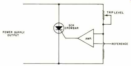
Fig. 5. Functional diagram of an overvoltage protection system.
As mentioned previously, the ferroresonant power supply is inherently current-limiting. Irrespective of load conditions, the output will never develop more than 200% of maximum current rating (maximum fault current will occur at short-circuit). The feedback-controlled regulated power supply is designed with electronic current limiting which holds the output current to a preset value, thereby providing protection for the load as well as the power supply. Removal of the load fault should result in normal power-supply operation without having to manually reset the supply.
Thermal Protection: Many power supplies are provided with a thermostat which automatically cuts off power when an overtemperature condition is sensed. This type of protection is primarily intended to prevent operation of the supply at load currents or ambient temperatures which exceed the manufacturer's ratings. Thermostats normally take several minutes to reset themselves once the cause of overtemperature is removed.
Overvoltage Protection: Excessive power-supply voltage output can be caused by power-supply malfunction or operator error. In either event, with today's delicate integrated circuits, excessive voltage can cause catastrophic failure.
Because the cost of protection is minimal when compared to the cost of the circuitry being powered, overvoltage protection has been adopted as a standard requirement by most power-supply users. The overvoltage-protection circuit should be an independent system, not having to depend on the power supply for anything other than as a source to be monitored. In the event of an overvoltage condition, the protection circuit will "crowbar" (short) the output by means of an SCR before the circuit limit is exceeded.
Refer to Fig. 5 for diagram of a simple overvoltage protector.
Undervoltage Detection: As explained previously, an undervoltage condition can cause loss of information in memory systems. Circuits are available which give an alarm should a power supply voltage output drop below the prescribed limit.
A Check List
Before selecting a power supply, a careful check-list should be made, which should include the following points:
1. Performance based on minimum circuit requirements
2. Power supply cost versus performance
3. Power supply cost versus application
4. Requirements for system circuit protection
5. Requirements for power-supply protection Such an evaluation can only be made if all the interrelated characteristics associated with the product are completely understood by the potential user.