By FRED HEATH, Applications Engineer, Trio Laboratories
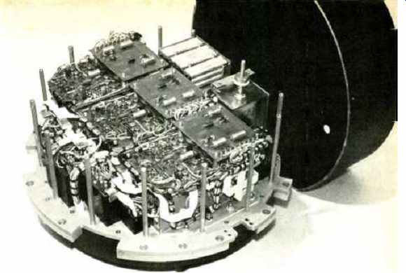
------- Bottom view of multi-output torpedo-borne power supply for
MK27 Torpedo Target Vehicle. Output power is 1.6 kW pulsed to 3.5 kW.
Efficiency is 80% and input power is 33 to 70 volts d.c. The temperature
range for this under-seas unit is 28 to 160 degrees F. Switching regulators
are used for high-efficiency regulation on this unit with five d.c. outputs
and one 115-V a.c., 400-Hz output.
Although more costly, the switching regulator power supply is lighter in weight and dissipates less heat than a conventional series-pass type of supply. Frequency range is 7-25 kHz.
BECAUSE of new advances in high-speed and high-power transistors, the switching regulator power supply has come of age and is now starting to become competitive in many areas where it was unheard of previously.
Generally, the term "switching regulator" is applied to any type of power-control device which regulates by alternately opening and closing some sort of switch. This switch is usually a transistor or an SCR, and control can sometimes be augmented by using a magnetic amplifier (mag amp). For the purpose of this discussion, only the transistor switching regulator will be considered, although mention will be made of both the SCR and the mag amp when pertinent.
The Switching Regulator
Basically, there are just two types of switching regulators: the series or buck regulator and the shunt or boost regulator. Fig. 1 shows both schemes. The series regulator allows current to flow to the LC filter when the switching transistor is "on" When the transistor is "off," the inductor keeps current flowing, with the flyback diode providing a return path. The output voltage is En = E;,, (T ,,,, l T nr, + L); thus the output voltage is always less than the input voltage.
The shunt or boost regulator, on the other hand, has an output voltage which is higher than the input voltage.
When the shunt transistor turns "on," the inductor prevents a step current load on the capacitor and the current through the transistor becomes a ramp function. When the transistor turns "off," the inductor prevents current from changing instantaneously and thus the current will flow into the capacitor and the load.
Switching feedback is accomplished by one of three methods. The first consists of keeping the frequency constant and varying the pulse width as a function of the output voltage. The second involves keeping the pulse width constant while varying the frequency (such as with a monostable multivibrator or one-shot). With the third method both frequency and pulse width are allowed to vary as a function of output by using a Schmitt-trigger-type device.
When using the third method the driver of Fig. 1 will be a Schmitt trigger controlled by the feedback circuit.
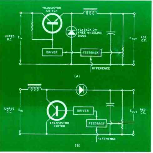
Fig. 1. There are two types of switching regulators (A) series or buck regulator,
and (B) the shunt or boost regulator.
The Inverter
Because of the need for input-output isolation, an inverter is usually used in a switching regulator-type supply. An inverter is a device which changes d.c. to a.c. In most pieces of equipment the inverter does this by alternately connecting the input d.c. to one side of a transformer primary and then to the other (as shown in Fig. 2). The switches, Si and S2, can either be transistors or SCR's. The output is a square wave which can either be rectified and filtered to provide a d.c. output or simply filtered to provide an a.c. output.
A device which adds rectification and filtering on the output of an inverter to make the output d.c. is called a converter.
Mag amps are sometimes used in series with the inverter switches to regulate current to the inverter transformer.
The control winding of the mag amp provides the feedback from the output. Using this scheme, a switching regulator, as such, is not necessary. A few years ago this technique was quite popular. Today, however, the cost of building a complex magnetic amplifier vs buying switching transistors makes the former choice uneconomical unless the ultimate purpose of the inverter is to provide a low-frequency a.c. output.
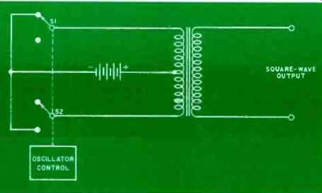
Fig. 2. Basic configuration of inverter circuit which changes d.c. to
a.c. by alternately connecting d.c. to one side of a transformer primary
and then connects it to the other side.
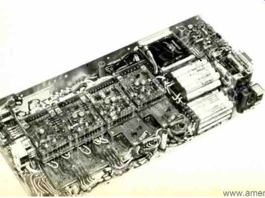
This supply designed for the F-111 has eight outputs with 150 watts delivered power in the temperature range of-54 to 95 degrees C. Built using many connectors, this supply has no board-to-board hand wiring and can be completely disassembled at PC card level in less than 20 min with screwdriver.
Oscillation control for the inverter can be supplied by one of a number of approaches. The simplest method is to have a separate oscillator which provides base drive for the inverter transistors. Another approach is to have a winding from the inverter transformer itself provide the base drive for the transistors. However, using this approach necessitates having some sort of start-up circuit to get the inverter cycling upon application of input power. Recently various schemes have been used in which the inverter transistors themselves are part of a built-in oscillator. Capacitance bridges or small timing transformers (or both) are designed to form a self-oscillating astable-multivibrator-type circuit with the inverter transistors.
If an inverter is being used with a switching regulator, the frequency at which the inverter is working is generally the same frequency at which the switching regulator will operate. This improves over-all power-supply stability and eases filtering for both the input and output lines. Using a common frequency, of course, implies that the switching regulator can provide regulation only via a pulse-width control approach.
The Power Supply
Many combinations of switching regulators and inverters can be and are used in the design of the complete power supply. A few of the possible combinations are shown in the block diagrams of Fig. 3. Fig. 3A is of a switching regulator power supply which regulates for line variation directly and for load changes via a feedback loop from the main (or only, as the case may be) output. Feedback is generally transmitted using some sort of chopper amplifier to maintain isolation. A series-pass regulator can be used (as shown) for low-power outputs and, because line regulation has already been taken care of, the efficiency is better than it would normally be for a pass regulator.
Fig. 3B shows the raw d.c. going directly into the inverter with regulation finally achieved just before the output by a switching regulator. This scheme allows quicker response to load steps. A series-pass regulator can, of course, be used at the output of the inverter, but since there is no line regulation, efficiency of this regulator will typically be low.
Fig. 3C shows separate switching regulators for line and load regulation. This allows faster response to load steps, with better over-all regulation, but with decreased efficiency. A series regulator hung off of the inverter in this approach will work very efficiently because it will see an input that has been regulated only for line variations.

Fig. 3. Several combinations of switching regulators and inverters.
(A) Regulator for line variations and for load changes; (B) Raw d.c.
goes directly to inverter with regulation achieved near the output;
(C) Separate switching regulators for regulation of line and load.
Frequency
One of the principal advantages of a switching regulator supply is light weight and small size for a given delivered output. Much of the benefit is derived from the frequency at which the inverter operates. Most switching supplies work with frequencies in the 7-25 kHz range. Since a transformer's size is highly dependent on the frequency at which it operates, a 60 or 400 Hz transformer used for isolation in a series-pass supply will be much larger and heavier than a high-frequency inverter transformer.
Lower limits on the inverter frequency are determined by two criteria: (1) the size and weight-obviously, if the frequency is too low the main reasons for using a switching regulator are negated; (2) audible noise-below about 12 kHz a switching regulator power supply can produce a high-pitched noise which is objectionable in many applications. For this reason many switching regulator manufacturers prefer to use switching frequencies above the audible range. However, with proper design of magnetic cores and sound packaging techniques, many high-power switching regulator supplies which use frequencies in the audible range are not, in fact, audible at all.
The upper limits on switching frequencies are determined by core losses. At frequencies above 20 kHz, efficiencies start to drop drastically and cooling becomes a problem if thermal runaway or the eventual degradation of the magnetic components is to be prevented.
Efficiency
Because in the basic buck (series) switching regulator scheme the transistor is used as a switch which is either full "on" or full "off," very little power is dissipated in the circuit. In the boost (shunt) switching regulator, because the transistor goes "on" more slowly, losses are somewhat greater. Efficiencies of a typical switching regulator power supply range from about 65 to 75% for a 5-volt output to about 85 to 90% for a 28-volt or higher output.
Greater efficiencies are important for a number of reasons. In airborne or shipboard applications where power is sometimes at a premium, a series-pass supply will generally dissipate more power than it delivers, while a switching supply will deliver at least twice what it dissipates. This means that a switching supply will reduce the heat given off by a complete system by more than one-third. This could easily mean that thermal problems will be reduced and reliability of the system (not just the power supply) will be increased. Because the switching supply itself doesn't dissipate much heat, heat sinks and other thermal conducting surfaces won't have to be quite so large, suggesting still further economies of volume and weight over series pass supplies.
Trade-offs of switching frequencies and efficiencies sometimes mean that although a higher frequency will reduce magnetic component sizes, the decrease in efficiency will necessitate larger heat-removal surfaces with no net decrease in the volume of the power supply.
Drop-Out
Since the input a.c. is rectified and filtered directly, storage of the raw d.c. is at a much higher voltage (165 volts). Since it takes a longer time to discharge the filter capacitors, a momentary decrease or drop-out of the input line will not cause a, like drop in the output voltage. A typical switching regulator power supply will operate for 30 milliseconds (fully loaded) to 60 milliseconds (half load) after a.c. power has been removed. This is especially important in computer applications where power must be removed from the memory before the logic starts to shut down. The input line can be sensed as low and the memory voltage can be crow-barred long before other voltages in the system go out of regulation.
Electromagnetic Interference
To many engineers the "switching regulator" is associated with electrical noise headaches. In the past this feeling may not have been completely unjustified. SCR switching regulators or inverters were used extensively and suppression of SCR switching noise is a difficult task at best. However, because of the many new high-power transistors introduced in the past couple of years, SCR's need not be used except when power requirements reach about 1000 watts. Shown on the front cover is an off-the-shelf 500-watt (5-volt, 100-amp) transistor switching regulator supply. This supply could not have been built a year and a half ago, using transistors which were available at that time.
Aside from using transistors as the switching elements, many other techniques evolved which have been used successfully for years in military applications. Here, size and weight have made the switcher a "must ", but EMI considerations are still critical. Some of these techniques include inverter oscillators using capacitive bridges which reduce switching spikes as they are produced, use of the boost (shunt) switching regulator which insures continuous current through the filter choke, careful wiring and printed circuit card layouts, and proper shielding of magnetic components and the unit itself.
Conducted interference on the input lines seems to cause the worst EMI problems. In a recent test, conducted for the U.S. Navy, using a simple rectifier circuit with a purely resistive load, it was shown that the rectifiers themselves caused an out-of-specification (MIL-STD-461) condition on the input lines at frequencies up to 5 MHz. This means that the rectifiers themselves turning on and off are responsible for much of the conducted noise. This source of noise is present whether an off-the-line switcher is employed or a series-pass supply is used, with the rectifier switching reflected through the input transformer. Proper input filtering is needed in any case. Because an off-the-line switching supply can more easily handle the input attenuation of such a filter, filtering for input-line-conducted interference is actually simpler to obtain in a switching supply.
The switching regulator doesn't do quite as good a job on containing output ripple and noise as a series-pass supply.
The switching regulator supply can generally be designed to have a maximum of 5 to 10 millivolts r.m.s. ripple and noise while the series-pass can get below 1 mV with no difficulty. For most applications, however, it makes no difference if the noise is 1 mV, 10 mV, or even 100 mV. Some logic designers will need the small size and weight of a switching supply, but will specify 1 mV of ripple and noise because that's what they saw on the data sheet for the series-pass supply they were using on the bench. Since most logic circuits have close to 1 volt of noise immunity, this is a clear case of over-specifying. Knowing exactly what the system requires is of prime importance in picking the right power supply.
Load Steps
One of the disadvantages in using a switching supply is its slow response to step-load changes. The feedback cannot be any faster than the maximum frequency of the switching regulator. Usually, because the switching regulator is ahead of the inverter, response times of several milliseconds are encountered. There are, however, a number of techniques for solving this problem. The best and most recent solution to this problem is the so-called "transient suppressor." During a step decrease in the load, this circuit clamps the voltage at a maximum level close to what it was before the step and absorbs the excess energy which is still being supplied to the output. During a step increase in load the voltage is clamped to a minimum level-again close to the original value-and the output is supplied energy until the switching regulator can meet the requirement. The transient suppressor is a passive-type circuit during normal power-supply operation and thus does not dissipate any power.
Another example of over-specifying is the case where a logic designer will call for a difficult dynamic-regulation parameter which increases the price of the power supply. In fact, a digital logic load will not vary more than 5% during a complete computation cycle.
-----This five-output supply provides 250 watts d.c. and 350 VA
a.c. for fans. It supplies logic and memory sequencing circuitry built
in to insure that memory is shut down before the logic. It is being
used in the Honeywell H316R computer.
Cost and Applications
A switching regulator power supply will always cost more than a series-pass supply with the same outputs. Presently, it costs anywhere from 25 to 100% more. As the price of switching transistors comes down (which they have already shown signs of doing), this gap will close, but the switcher will always be more expensive. To understand why is simple if you refer to Fig. 3.
Even if the cost of the switching regulator and inverter approach the price of the series-pass circuitry, the over-all switching supply always contains two sets of rectifiers and filters, one off –the-line and one at the inverter output.
The series regulator power supply, on the other hand, uses only one rectifier-filter combination.
Until recently the only people who would spend the extra dollars for a switching supply were those working on military contracts. For aircraft, shipboard, and mobile ground-support equipment weight, volume, and efficiency are of utmost importance.
Where weight penalties can be applied, the added cost of a switcher was minor when compared to penalty dollars. Most pieces of gear had to fit in a fixed volume. When most of that volume was allotted to the rest of the system, the power supply had to fit into the tiny space that was left.
Now, with MSI and LSI, computer and peripheral manufacturers are able to make complex equipment in very small boxes. And because logic speeds are increasing along with the watts per logic function, these small boxes use huge amounts of power. There are now many instances where a series-pass supply is larger, heavier, and dissipates more power than the computer it is driving. If nothing else this is not aesthetically pleasing. If you are trying to sell a desk-top computer with a power supply which is as big as the desk, you can understand the problem. Thus many computer people are looking to switching supplies. Companies using switching regulators right now read like a "Who's Who" of the computer industry: IBM, Honeywell, Univac, DEC, Burroughs, and RCA, to name a few.
Besides aesthetics, there are solid dollar reasons why the switcher makes sense to the computer industry. Thermal problems which necessitate a complex cooling system with a series-pass supply are sometimes eliminated by using a switcher. The cooler running switching supply means less temperature stress on components and greater reliability or MTBF (mean-time-between-failure) which, in turn, means lower maintenance costs.
There are applications where a switching regulator would make sense; but often is not used simply because the engineer is unfamiliar with the technology or has doubts about EMI. As more and more switching regulator power supplies are designed into new hardware this reluctance will disappear. Of course, for every application where a switching regulator is a must, there are many more where the extra cost isn't justified. As new and better transistors are introduced and as the recent arrivals start to drop in price, it will become harder not to consider a smaller, lighter, more efficient, and more reliable power supply for tomorrow's state-of-the-art designs.