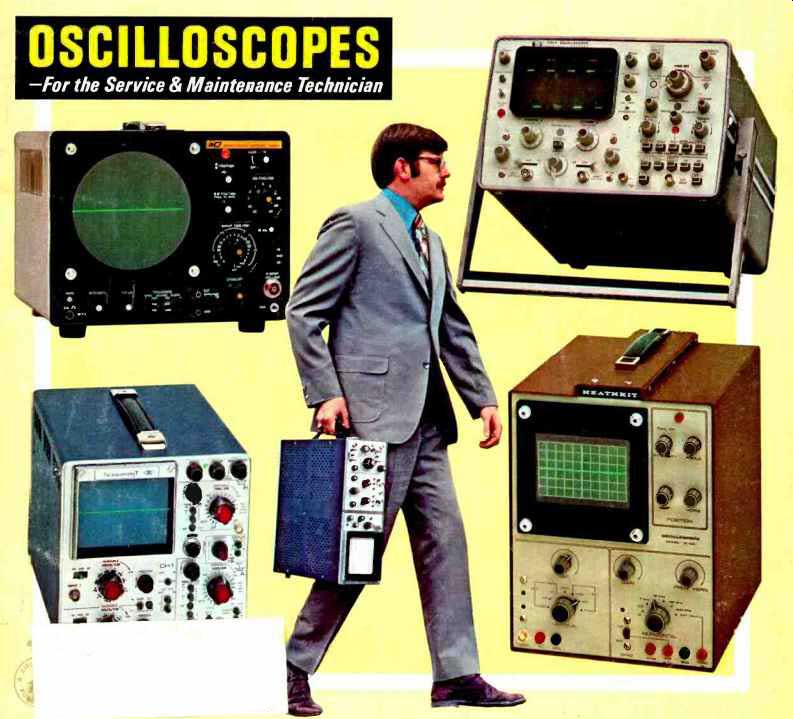
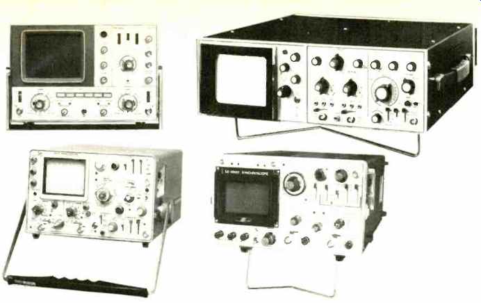
---Above: Some of the newer bench type scopes: Heathkit 10101 vectorscope; Sencore PS163; Lectrotech TO -50; Simpson 458. Below Eico 465. Bottom (from left to right): Leader LBO -301; Hickok 5002: Kikusui 5122; RCA WO -33A.
By STANTON R. PRENTISS
Author. "How to Use Vectorscopes. Oscilloscopes & Sweep-Signal Generators".
New and more sophisticated circuits call for equally sophisticated test equipment. Here's the rundown on portable and bench models.
(source: Electronics World, Nov. 1971)
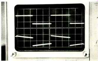
Fig. 1. The 6 10 graticule of a modern scope. Upper waveform is perfect
square-wave; lower shows tilt due to I.f. phase shift.
Fig. 2. (Left) Upper waveform is sync output of a TV receiver; lower trace shows the vertical driver output. (Right) Upper trace shows SCR conduction in horizontal output circuit of RCA CTC 46; lower, differentiated output of horizontal blocking osc.
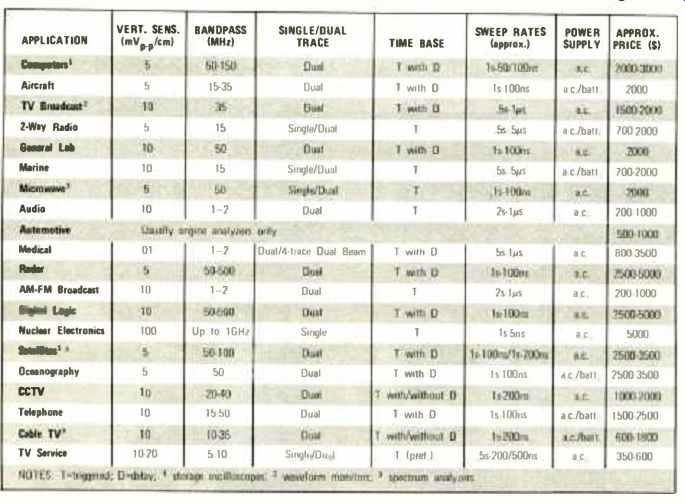
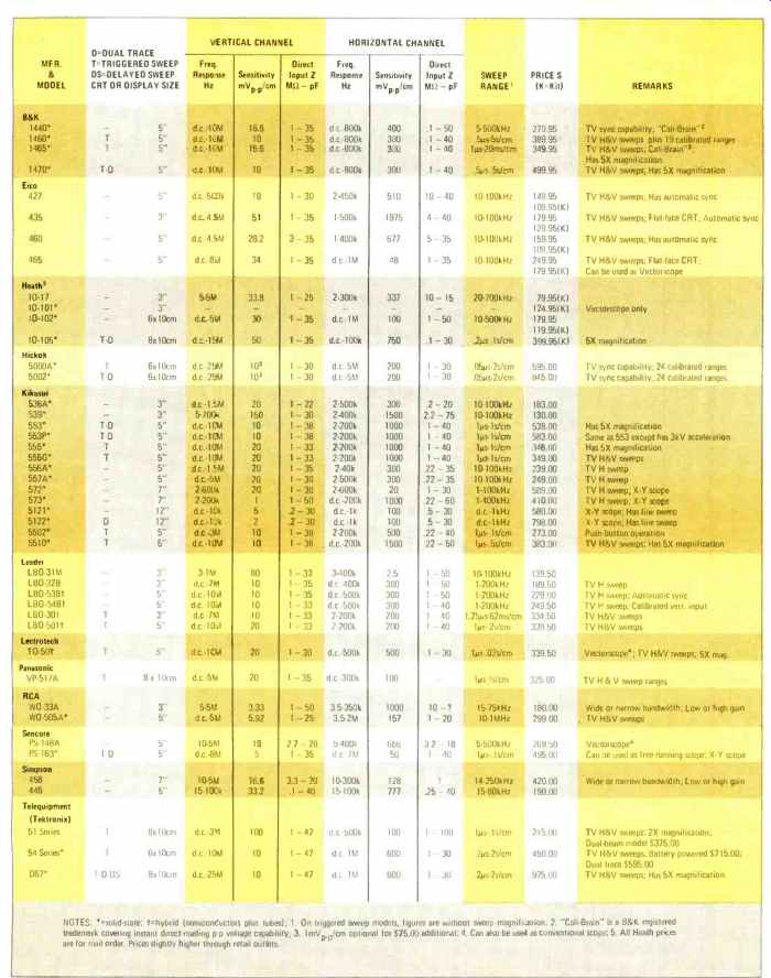
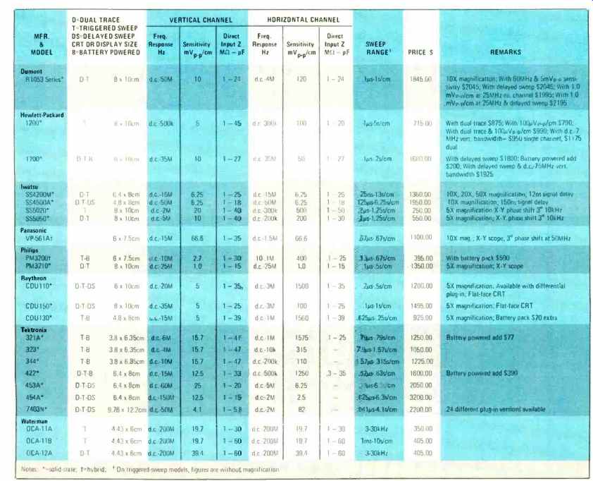
Table 1. Scope features required for various types of service work and
their price range.
THE days of relay switching and slow, current-consuming vacuum tubes have yielded to the transistor; computer; nanosecond logic; high-gain, high-slew-rate operational amplifier; light-emitting diode; ion implant; molecular electronics; and more. Today, emphasis is on gain and speed. Not long ago a bandwidth of 15 MHz was considered exceptional; now 500 MHz to a GHz is a reality. As one active element reaches a certain complexity and speed, another device is developed that surpasses it. There is a price to pay, however. The equipment required to test and analyze these fast, high-gain circuits must be equally sophisticated. One of the more versatile test instruments--the oscilloscope-is available over a wide price range and an equally wide range of sophistication. When purchasing a scope it is logical to select a unit that is adequate for the task at hand, but it is wasteful to choose one that is unnecessarily complex and costly.
All better standard oscilloscopes are judged by the capabilities of both the vertical and horizontal amplifiers, sweep speeds, and dual- or single-time base. Obviously, the less expensive scopes have fewer features. For instance, if the scope you are contemplating has a delay line for X-axis trigger-signal coincidence, a vertical amplifier with a bandwidth of 50 or more MHz, and a dual time base from about two seconds to 100 nanoseconds, then it is going to fall into the $1700-$2500 bracket. On the other hand, a scope with an a.c.--only vertical amplifier, recurrent sweep (no calibrated time base, only gross frequencies), vacuum tubes, and a five-inch CRT, in kit form or built, can cost from $180 up.
In between is the scope with a 10 or 15 MHz a.c. - d.c. vertical amplifier with no delay line but with triggered sweep from about 0.5 second to 500 nanoseconds, that can retail from $340 to $450 and have its calibrated accuracy well within 5 %. What overall accuracy do you really need? A new oscilloscope, with acceptable tolerance and guaranteed for a vertical-horizontal calibration of 3% is probably good over most of its ranges for 2 %, at least for the first year. Thereafter, with aging components and a few beta changes among the various transistors, the accuracy (without calibration) will probably stretch to between 4% and 5 %. It would not be difficult, however, to recalibrate to within at least 3 %. On the other hand, an inexpensive scope with initial tolerances of 10% can drift considerably between relatively frequent calibrations. In short, the better scope always has greater accuracy, less drift, and usually much longer periods of service between breakdowns.
Bandwidth /Sweep-Amplifier Relationships
There are certain relationships (and tradeoffs) between the various scope characteristics. For instance, a scope containing amplifiers with wide bandwidths will insure both a better rise time and usually greater sweep ranges, particularly at high frequencies.
The rise time of an amplifier is related to the bandwidth by t,. = K/BW, where the factor K is generally 0.35. Therefore, for a bandwidth of 15 MHz, the rise time will be t,. = 0.35/15 X 106 = 23.3 X 10 -s or 23.3 nanoseconds. Such oscilloscopes have sweep speeds from 200 to 500 nanoseconds with 5X magnifiers that permit them to show expanded rise and fall times as low as 40 nanoseconds provided, of course, that the cathode -ray tube has sufficient accelerating voltage to make the trace visible.
Along with wider bandwidth and faster horizontal sweep comes an improved vertical deflection factor. This is sometimes expressed in terms of deflection sensitivity (the inverse of the deflection factor) but such a description normally applies to the scope's CRT. Today's scope manufacturers use the deflection factor to express amplifier sensitivity, where vertical amplifiers are calibrated in volts per division (V/ div) whether they are measured in whole or fractional centimeters or in the antiquated unit of V /inch. The use of voltage divider and low-capacitance probes has expanded the voltage range of scopes from microvolts / per division to as high as 500 V /division.
The better oscilloscopes use a graticule with a 6 X 10 or 8 X 10 division.
The 6 x10 graticule is shown in Fig. 1.
Also shown in Fig. 1 is the effect of not using a low-capacitance probe (lower trace) for low frequencies with an a.c. amplifier. The phase shift of the low frequency components causes the waveform to tilt. The d.c. amplifiers, of course, show no tilt if they are properly compensated.
A 10:1 low-capacitance probe also adds 9 megohms to the normal 1-megohm input impedance of the oscilloscope while, at the same time, lowering the effective input capacity of the instrument.
For some types of measurements and observations in radio-frequency and intermediate-frequency circuits, diode demodulator probes are required.
---General-Purpose Oscilloscopes tor Servicing
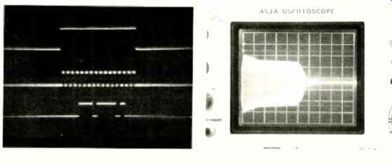
Fig. 3. (Above) Pulse train from computer shown on storage oscilloscope;
(Above right) Output waveshape of marine depth finder; (Bottom right)
Modulation envelope of a marine transmitter modulated by a 2 -kHz audio
-frequency tone.
D.C. Vertical Amplifiers
The d.c. vertical amplifier has no coupling capacitors and any d.c. input to the scope will be shown by a shift of the race. A direct -coupled amplifier is more complex and costly and the prospective purchaser should question its importance to him. This is especially true of the experimenter.
For example, in vacuum-tube circuits using the normal "B" supply voltage of 250 volts, the actual d.c. plate voltage is usually so high that using the d.c. amplifiers of the scope will flip the trace off the screen unless the vertical amplifier sensitivity is reduced. With reduced sensitivity, the a.c. portion of the signal would be difficult, if not impossible, to read. For example, a 20 -V p -p waveform swinging on a 400 V d.c. level would occupy only 1 /20th of the display and would be completely lost. On the other hand, a 15 -V p -p signal riding on 30 -V d.c. level would represent a 2:1 ratio and would be easily visible. This would indicate that scopes with d.c. amplifiers would have greater application in low d.c. voltage circuits -those using semiconductors -where a.c. and d.c. measurements could be made simultaneously and use of a meter avoided.
A d.c. voltage can be measured on the scope simply by observing the number of divisions it causes the trace to shift and then multiplying this figure by the vertical amplifier setting, taking into account the effects of any probe being used.
If you are an experimenter and your projects are con fined to vacuum -tube circuits, consisting of low-frequency oscillators, amplifiers, or stereo units, a relatively inexpensive scope will serve your purposes. It must, of course, be linear, have a bandwidth of from 1.5 to 3 MHz, a sensitivity of at least 50 mV /cm, and a normal input impedance of 1 megohm. The scope will have to be supplemented by a meter for the measurement of d.c. voltages and no accurate frequency measurements can be made with this type of unit. If you wish to compare stereo output channels, the scope will have to have matched vertical and horizontal amplifiers to prevent phase shift. If this is not available, the scope may provide direct access to the deflection plates.
With this arrangement, non-amplified Lissajous patterns can be used to determine phase and frequency relationships.
Should you be more ambitious and want to measure time or frequencies to within fairly close tolerances, then you must give up recurrent sweep with its gross calibration and purchase a time -base scope accurate enough for your purposes. Failing this, you can purchase an electronic counter to make your time and frequency measurements. While an improved scope will double your expenditure (still cheaper than the counter), it will also include d.c. amplifiers, an improved deflection factor, greater bandpass, and relegate your d.c. meter to measuring resistance or dB. The TV Service Technician What used to be an area of point -to -point wiring, sizzling tubes, and 380 -V low -voltage power supplies -the TV set has now changed drastically. Modular plug -in boards, IC's, transistors, 35to 150 -volt power supplies, and high-voltage triplers and quadruplers are here now -not in the future.
The inexpensive non -linear a.c. scope kit of the past, which was dusted off only on special occasions, is not too useful today. To troubleshoot the new solid -state TV receivers, with or without plug -in boards, a completely new approach is needed.
There are many more 5% tolerance resistors, closer tolerance capacitors, and transistors whose beta ratings must remain high to drive their dependent circuits. There are also direct -coupled amplifiers, digital gates, silicon controlled rectifiers, unijunction transistors, metal -oxide semiconductors, and just plain silicon transistors. These esoteric circuits and devices just don't respond too well to servicing with a 20k ohm /V multimeter. Measuring static power -supply voltage was satisfactory for vacuum -tube circuits, but is not for semiconductor troubleshooting.
The TV technician must attack his problems with a good oscilloscope in order to locate the offending part more easily. What component will it be? Usually a semiconductor as long as the biasing resistors are mostly 1/2 watters and the big capacitors haven't yet aged. Occasionally there will be an open coil or transformer, but most of the problems will be caused by marginal rather than completely defective transistors.
How can this type of problem be handled? Probably in no other way than with a scope containing triggered sweep and d.c. amplifiers. Initially, you'll require d.c. accuracy to at least 5% in order to eliminate the need for separate d.c. measurements with a meter. You can simply measure the a.c. and d.c. voltages simultaneously. An accurate time base is also necessary so that you can measure the frequencies in the horizontal and vertical circuits.
The scope can also be used to test for horizontal signal components in the vertical circuit and vice versa, poor oscillator output, and other vague types of difficulties that cannot be located or identified without a good scope.
As an example, consider the dual -trace display of Fig. 2 (left); the top waveform is the 16.67 -ms (60 -Hz) sync output waveform while the lower trace is that of the vertical driver. Observe anything unusual? The sweep is set for 5 ms/ cm. Since f= 1 / T, the lower trace is f= 1 / (2.8 X 5 X 101 = 73 Hz. Since the vertical frequency of a color transmission is 59.94 Hz, you know immediately that the lower trace is much faster than the sync trace and the receiver is well on its way to doubling its vertical frequency.
The frequency of the upper trace works out to f= 1 I (3.8 X 5 x 10-s) = 53 Hz. Since the transmitted sync signals are actually 59.94 Hz, you might assume this scope to be slightly off calibration and you'd be correct.
It might be well at this point to note that there is a difference between a dual -trace and dual -beam scope. The dual trace scope permits two presentations by switching the beam back and forth rapidly, while a dual -beam scope actually has two electron guns in the CRT which generate two independent beams.
Another application of the time-base scope is shown in Fig. 2 (right). The bottom trace is that of a differentiated output of the horizontal blocking oscillator of an RCA CTC 46. The top trace is the 330 -V p -p output of the horizontal SCR. Ground is the center line and cut off the top line of the graticule. With the time base set at 20 µs, the horizontal frequency can be calculated from f = 1/ T = 1/ (20 X 10-6 X 3.7 div) = 15.8 kHz; a figure very close to the 15,734.264 -Hz color scanning rate. As you might also suspect, this is a convenient way to check or calibrate your scope. Done very carefully you can achieve 2% to 3% accuracy. With horizontal and vertical frequencies translated into time-base information, you can check sync circuits, identify hum, transients, and other peculiar manifestations.
One further point deserves mention here. Obviously, a dual -trace scope has been used. Does TV work require two traces? If you are willing to spend between $500 and $1500 for a scope to service semiconductor equipment and want to work quickly, accurately, and dependably, get dual trace. While you're about it, invest in a pair of suitable low capacitance probes.
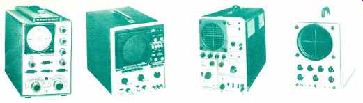
---Some portable oscilloscopes currently available include: (top
left) Philips PM. 3210; (top right) Du mont R1053; (bottom left) Tektronix
453A; and (bottom right) the Iwatsu SS4500.
above: Portable Oscilloscopes for Servicing
A good test for a scope to determine its suitability for TV work is to see if the trace is steady with internal sync at 60 Hz or below; if a 3,579.545 -MHz chroma oscillator sine wave is resolved cleanly and broadly; if the trace is still sharp, bright, and noise -free with maximum vertical amplifier gain; whether the scope will sync on a signal that is a portion of a division /cm; and if there is abnormal d.c. amplifier drift after warm -up.
Industrial /Laboratory Scopes
Now let's consider professional scopes that require the best accuracy, fast writing rates, a variety of vertical amplifier types, and a time base whose speed must range from fast to spectacular. These oscilloscopes are expensive, ranging from $1500 to $5000. They must operate over long periods of time, sometimes at above-normal temperatures, and with little or no maintenance.
The standard scope in this price class (and we're not speaking of spectrum analyzers, sampling, or storage oscilloscopes) must have high sensitivities (as low as 10 mV /cm or less), rise times in the low nanoseconds, bandwidths wider than 20 MHz, special time -base triggers for low -level and very rapid signals, and usually two time bases (A delayed by B) so that small portions of a waveform can be observed in detail.
While the above requirements almost dictate the need for plug -in amplifiers, smaller, lighter scopes are rapidly appearing on the market without plug -in capabilities but with characteristics broad enough so that they will do for many applications. If this is not the case then there are the larger scopes which accept plug -in amplifiers that offer vertical differentiated amplifiers with 10 -µV sensitivity, operational amplifiers, transducers, strain gages, current amplifiers, 4 -trace amplifiers, and even multimeters and counters (Tektronix 7400 Series). Very important, too, is the 4 to 12 kilovolts, or more, supplied to the CRT accelerating anode which permits trace resolution at extremely fast repetition rates.
These professional -type scopes also contain regulated power supplies in order to maintain steady-state characteristics over a prolonged period of time after calibration. The less expensive scopes must depend upon the regulation of the a.c. power line and this can cause inaccuracies even over short periods of operation.
Battery-Operated Scopes
Battery-operated scopes have become popular with the advent of low voltage and low -current transistors and special cathode -ray tubes. Both Hewlett-Packard and Tektronix have quality scopes in portable form which can be operated from batteries or a.c. power. Practical continuous operating time varies from 3 to 8 hours depending of course on the particular design, with all vital characteristics maintained over this period. In all probability the only real limiting factor is the current drawn by the CRT filament.
The portable scope finds its application on such jobs as aircraft maintenance, telephone long-lines, balloon electronics, shipboard communications, mobile rigs, and just about any application where no power lines are available. As far as price is concerned, the portable scope is bound to run higher.
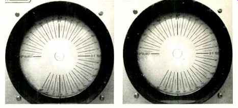
Fig. 4. (Left) A vectorscope pattern with luminance information; (Right)
The correct vectorscope pattern with luminance removed.
Professional Scope Specs /Uses
Since scope characteristics are pretty well covered, we can now set up a table of typical specifications needed for the various areas of the industry and the NASA-Military.
Jim Walcutt of Tektronix helped with this chart and it includes information on sensitivity, bandpass, single- or dual trace, time base (delayed or not), sweep rates, a.c. or battery-operated, and round-figure prices. Along with the table and discussion, we will show some typical waveforms from some of the gear described.
Computers: These can be analog or digital, but digital are faster, so we will take a look at one of this type. Ken Wallgren of Goddard Space Flight Center had us take a look at the pulse train in a 750 -nanosecond Systems Engineering Laboratories' 810B computer which will fetch and store usually in two cycles of the sub -microsecond rate. The display (Fig. 3) was made from a storage oscilloscope, accounting for the murky background.
Marine Depth Sounder. The trace shown from this unit (Fig. 3), appears as an amplitude -modulation envelope but really is the r.f. output of the sounder taken at 100 V /div and 100 µs /div on the X -axis. Slower sweep speeds simply show large pulses of voltage at regular intervals emanating from the depth sounder.
Konel Marine Transmitter. The output of the transmitter display at 2 V /div and 0.5 ms /div (Fig. 3) shows the effects of a 2 -kHz whistle. The rig (and whistle) was supplied by Alfred Fry III of Fry Electronics, Annapolis, Maryland.
Service Vectorscopes
The "garden 'variety" of vectorscope is a most useful instrument for making all Lissajous phase and frequency comparisons. It is ideal for color -TV troubleshooting as it can check chroma bandpass, burst transformer, 3.48 -MHz subcarrier output transformer alignment, and peaking. For stereo work it can be used to check the 19kHz - 38-kHz pilot to regenerated subcarrier precision alignment by a 2:1 discrimination.
Any oscilloscope can be a vectorscope since it has a set of both vertical and horizontal deflection plates. You can feed the plates through the X and Y amplifiers provided they are linear and matched for equal deflection and impedances.
Because of the voltages involved, capacitive coupling should be used from the signal source to the amplifier inputs or to the deflection plate connections at the rear of the scope. When feeding the deflection plates for vectorscope operation, one plate of the V and H must be grounded for a.c. (no push -pull operation). Further, both V and H plates must be reversible for color-grid drive or cathode drive which, of course, are 180° out-of-phase.
In addition to feeding through coupling capacitors you'll need an RC compensation network for the red amplifier to match the blue in order to produce a rounded pattern.
Some scopes designed for color work have this built in. Others require an outboard network that would consist of approximately 180 pF in parallel with 390k ohms in series with the TV red signal.
Another concern is whether the vectorscope loads the signal source being observed. If the scope has a low input impedance, the loading will cause phase changes ( Hue shifts) and the colors will shift positions.
Vectorscope Signal Generator
Since you are going to view patterns that are 90° out–of-phase, a very clean signal source is necessary for the amplifiers under test. Sine -wave inputs must have little or no harmonic content and other signal generators, particularly gated-rainbow color-bar generators, must be free from fundamental gating "spray" (usually 189 -kHz oscillations) to produce a clean, distortion-free pattern in the receiver's R -Y (red luminance) and B -Y (blue luminance) outputs. G-Y is not used since it is more than 180° from the reference 0 -360° burst and more than 90° from R-Y. Any color pattern that has patches of bar internal interference or runs rapidly up and down probably has such gating problems. On the vector pattern, this will show as a smear among the bars.
Other generators will not show blanking between 300° and 360° and will cause one or more bars in the vector output to distort, usually the first or tenth.
As examples of vector patterns we chose to use RCA's modular plug-in, solid-state 1972 color receiver. Fig. 4 (left) is an example of a vectorscope display with the luminance information still left in the pattern. The signal is fairly readable but somewhat distorted. Fig. 4 (right) shows the correct vectorscope pattern with the luminance removed and all petals of the vector pattern in their correct (approximately) position. The sharp rise and fall times of the third R -Y bar verifies the fact that the bandpass transformers are tuned correctly.
X -Y Scopes A type of instrument that is increasing in popularity is defined as the X-Y scope. This scope is different in that it has matched vertical and horizontal amplifiers. They are matched in input impedance, input capacitance, gain, frequency response, and -most important of all -phase shift.
Some models list a phase difference of only a degree. The advantage is that the scope can be used to determine the phase difference between two signals (without actually adding an error due to its own phase shift), using Lissajous patterns.
For this reason, the X-Y scope can readily serve as a vectorscope for color-TV work provided it has an adequate bandwidth. Unfortunately, many vectorscopes cannot double as X-Y scopes since they have insufficient gain.
Also see: