AMAZON multi-meters discounts AMAZON oscilloscope discounts
The Chromatic Probe* is a unit designed to convert the outputs of r.f. sweep and signal generators so as to meet the sweep requirements of video amplifiers and color TV circuits. The purpose of this probe is to supply a video-frequency signal for the proper alignment and servicing of color TV, as well as mono chrome (black and white) receivers. Such a probe is important (particularly for color TV) since very few of the present signal generators have a video sweep.
Probe circuit
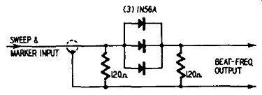
Fig. 901. Electrical arrangement of the Chromatic Probe.
Fig. 901 shows the circuit arrangement. It is essentially a nonlinear mixing device using three 1 N 56A crystal diodes connected in parallel. The heterodyning (mixing) action of the probe results in an upper and lower sideband when two different frequencies are applied to its input. The probe input connector is plugged into the signal terminals of an AM and an FM generator. The signals from these two different generators are then mixed in the probe network. The difference frequency between the FM and the AM generators becomes available across the 120-ohm diode load output resistor shown in the illustration.
This difference frequency can be used to test the video-frequency circuits of a TV receiver. Fig. 902 shows the internal layout of the probe. The small size of the probe is indicated by the ruler against which it is placed.
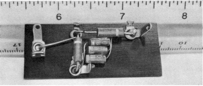
Fig. 902. Internal layout of the Chromatic Probe. The three crystals form
a non linear network. The output of the probe is the difference between the
two signals that are applied to the probe input.
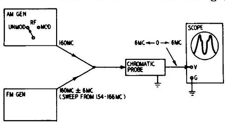
Fig. 903. Example of how a 6 -mhz video sweep is developed. For the settings
noted, the video voltage sweeps through a 6 -mhz band twice in 1/120 second.
Development of a wide-band video sweep
In operation, the function selector of the AM generator is set to the unmodulated r.f. position. The FM generator is set for a sweep width of several or more megacycles, depending upon the bandwidth of the circuit under test. The tuning dials of both generators are set to the same frequency. If the dial of the AM generator is set to 160 mhz, then the dial of the FM generator will also be set to 160 mhz. The output from both generators is applied to the input of the probe, as shown in Fig. 903. Setting the generators in this way will produce a twin image on the scope screen.
Single-image response
Response curves are customarily specified singly (not as twins, or mirror images) hence it is preferable to set the generator dials to obtain the sweep display only once each 1/120 second.
When the dials are set to the same frequency, as shown in Fig. 903, twin curves are displayed on the scope screen. When the dials are as shown in Fig. 904, a single curve appears on the scope screen in standard form. If some other sweep width such as 6 mhz were to be used, then the AM generator could be set to 160 mhz and the FM generator could be set to 163 mhz to obtain a standard form of response curve display.
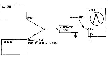
Fig. 904. To obtain a response curve in standard form it is necessary to develop
one video sweep in each 1/120 second.
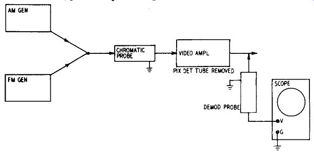
Fig. 905. Basic arrangement for sweeping a video amplifier. The out put from
the probe substitutes for the output from the picture detector.
Consider a typical operating condition in which a 160-mhz center-frequency signal from a sweep generator is swept over a 5 -mhz band, from 157.5 to 162.5 mhz, and in which a 157.5-mhz signal from a marker generator is mixed with the sweep signal. The probe modulates these signals and generates an upper and lower sideband. The lower sideband sweeps from 0 to 5 mhz and is the signal that interests the color TV technician. It is the signal output used to sweep-check the Y amplifier, I, Q, chroma amplifier and chrominance circuits.

Fig. 906. Resistor R substitutes for the plate resistance of the picture detector.
Using the Chromatic Probe
In Section 2 we showed how you could obtain a video response curve through the use of two generators and a crystal demodulator probe. The same curves can be obtained without beating the test voltages through the picture detector when the Chromatic Probe is used. This is accomplished by using the Chromatic Probe to substitute for the action of the picture detector. The test setup is shown in Fig. 905. The output from the Chromatic Probe is applied at the input of the video amplifier. This elementary arrangement must be suitably modified to provide proper values of source impedance when various video amplifier systems are under test.
This arrangement does not provide as high a value of source impedance to the video amplifier as when the test signals are beat through the picture detector, hence the high-frequency response may appear abnormally high, unless a suitable series resistor is included in the arrangement as shown in Fig. 906.
The value of the series resistor R should be made approximately equal to the a.c. plate resistance of the picture detector in order to obtain the same shape of response curve as when beating the test signals through the picture detector. This value may be found from tube handbooks or from crystal diode data sheets.
When making video-amplifier checks, it is desirable to keep the cable for the Chromatic Probe and the demodulator probe well separated. Otherwise you will find that sufficient coupling exists between the two cables to cause a displacement of the zero-volt reference line. Such displacement does not impair the accuracy of the curve display, but causes the zero-volt reference line to drop below its normal level on the scope screen.
D.c. voltage at video amplifier input A problem is sometimes presented by the presence of a d.c. voltage at the input of the video amplifier. In such cases, the probe loading resistor must not be permitted to drain off the d.c. voltage. This requires the use of a blocking capacitor as shown in Fig. 907. To choose a suitable value of blocking capacitor, remember that the reactance of the capacitor should be less than 0.1 times the value of the input impedance of the video amplifier at the lowest frequency of test.

Fig. 907. A blocking capacitor, C, is used whenever a d.c. voltage is present
at the video amplifier input.
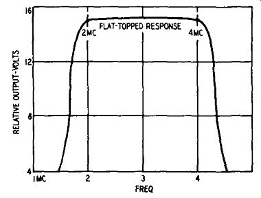
Fig. 908. Ideal response in output circuit of chrominance amplifier.
To make a sweep-frequency test, usually the lowest frequency of concern is 50 khz. If the 100-ohm termination of the probe is to work into a contrast control having a value of 500 ohms, for example, the reactance of the blocking capacitor should be less than 50 ohms at 50 khz. This means that the capacitor should have a value of at least .05 µf. To make a 60-cycle square-wave test, the value of the capacitor must be increased to present a reactance no greater than 50 ohms at 20 hz. This requirement may appear to be excessive, but remember that good 60-cycle square wave response requires relatively flat frequency response down to 20 hz.
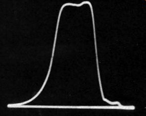
Fig. 909. Actual response curve in chrominance amplifier output circuit using
Chromatic Probe.

Fig. 910. The I synchronous detector curve. Note the peak at 1.5 mhz.
Testing color TV
There are many circuits in a color TV receiver that require video-frequency amplification, as compared with the usual single amplifier in a monochrome chassis. Fig. 908 shows the ideal response of a bandpass amplifier, as found in the output circuit of the chrominance amplifier. For comparison, Fig. 909 shows an actual response curve obtained with the Chromatic Probe.
Fig. 910 shows the ideal response for the I-channel synchronous detector. Fig. 911 shows the response obtained with the probe.
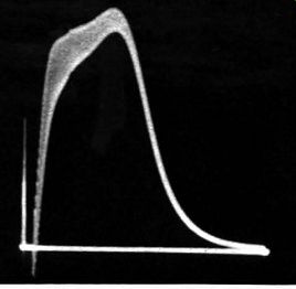
Fig. 911. The I synchronous detector curve obtained with the probe.
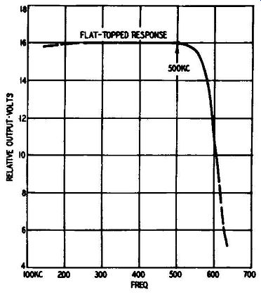
Fig. 912. Frequency response curve of the Q synchronous detector output.
The fuzz is caused by incomplete rectification and filtering of the peak-to-peak high-frequency probe, which also attenuates the extreme low-frequency response.
The frequency response of a Q synchronous detector output circuit is shown in Fig. 912. Fig. 913 shows the response obtained with the probe. The large amount of un-rectified and unfiltered fuzz is due to the use in the test of a different type of demodulator probe that uses a relatively small value of filter resistance in its output circuit. It is apparent that the appearance of the video display is greatly dependent upon probe characteristics.
Certain video circuits in a color receiver are adjustable, while others are not. The Y channel, for example, is not adjustable and in the IQ system utilizes a 1-µs delay line. It is not recommended that the technician attempt to sweep the Y channel because the delay line rings strongly and makes the test difficult to interpret. Instead, various receiver manufacturers recommend that the Y channel be checked out on the basis of d.c. measurements.

Fig. 913. Q synchronous detector response obtained with the probe. Results
that you get depend on type of demodulator probe that is used.
In a typical receiver, the I demodulator, the Q demodulator and the chroma amplifier contain adjustable inductors. No delay lines are included in these circuits and a ringing problem is not encountered. Fig. 914-a shows a suitable test setup for checking the chroma amplifier. This circuit includes a bandpass filter, with frequency limits from 2.1 to 4.2 mhz in a typical receiver.
Always consult the manufacturer's data and make the tests under the conditions specified. The example cited is only typical.
In this test setup, the output from the Chromatic probe is applied to the control grid of the chroma amplifier. This circuit has no external d.c. bias applied to the grid of the tube; hence no blocking capacitor is required between the Chromatic Probe and the grid terminal. The shape of the response curve being unaffected by the value of the output impedance of the sweep generator, no pad is required between the Chromatic Probe and the grid terminal.
The crystal demodulator probe can be conveniently applied across the color intensity control. If a half-wave type of probe does not provide full screen deflection on the scope, a video voltage-doubler probe of the type previously described can be used. In a test of this type give no consideration to the loading effect of the probe, since it is being applied across a low-impedance point in the circuit (the color intensity control of the receiver, 500 ohms).

Fig. 914-a. Test setup for obtaining the response of the chroma amplifier
(bandpass filter) in a typical color Tv receiver. The output from the probe
is applied directly to the grid of the chroma amplifier.
Output from the color intensity control is demodulated through a half-wave or voltage-doubler probe, and applied to the vertical input terminals of a scope.
In the example cited, the low-frequency response of the curve drops somewhat when the output from the Chromatic Probe is applied to the input side of the grid capacitor, as shown in Fig. 914-b. This drop in low-frequency response is caused by the greater reactance of the 50-µµf capacitor at 2.1 mhz as compared with its reactance at 4.2 mhz. (1,500 ohms vs. 750 ohms). This is an illustration of the necessity for consulting the test conditions specified by the receiver manufacturer before comparing curve shapes.
Since there is a d.c. voltage present on the input side of the coupling capacitor, a blocking capacitor should be used in series with the output from the Chromatic Probe. This capacitor avoids drain off of the d.c. voltage through the probe and also prevents biasing of the crystal diodes to an unfavorable operating point.
In some situations of this type it is possible to injure the crystal diodes or to damage receiver components if the blocking capacitor is not used.
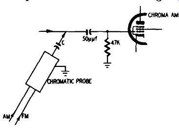
Fig. 914-b. When the output from the Chromatic Probe is applied to the in
put side of a 50-µµf capacitor the low frequency end of the response curve
is attenuated. The capacitor has a higher reactance at the low video frequencies
than at high video frequencies. Blocking capacitor C may be approximately .05
µf m this type of application.
Modifications
The probe will not work unless both sweep and CW output are applied. Since many generating units provide separate sweep and marker CW outputs, it is necessary to make a suitable mixing arrangement before the probe can be used. One practical solution is to remove the connector provided with the probe and substitute a Y connector to handle the output cables from the sweep and marker generators. Upon occasion, standing waves may cause trouble, but in most cases it is possible to select suitable generator frequencies to minimize the loss of flatness.
The generator frequencies should also be pure fundamentals (not harmonic or beat frequencies) or unusably low and distorted outputs will probably plague the technician. This point requires careful consideration, since the marker generator may not operate on pure fundamentals above 60 mhz, delivering only harmonic output, while the sweep generator may not deliver pure fundamental output below 75 mhz. In such case, suitable generating equipment must be obtained or use of the Chromatic Probe becomes impractical.
Demodulator probe limitations
In Figs. 905 and 914 we showed the use of a demodulator probe in connection with testing video and chroma amplifiers.
While the Chromatic Probe provides output down to 8 khz, permitting unusually low-frequency tests to be made in color TV circuits, conventional demodulator probes do not respond below 50 khz. If you want to check the extreme low-frequency response of a chrominance circuit, the scope must be applied directly (or via a low-capacitance probe) at the signal take off point in the receiver. This procedure does not develop a conventional response curve, but a "modulated carrier wave" type of display. The envelope of this display is the frequency response of the circuit.
Chromatic Probe maintenance

Fig. 915-a,-b. Response curves: a, using demodulator probe; b, using low-capacitance
probe. "A" is the area of low frequency attenuation.
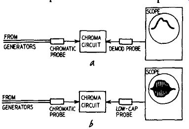
Fig. 916-a,-b. Chromatic Probe test setups.
The cop illustration, a, shows the use of a demodulator probe, while the lower illustration, b, shows a low-capacitance probe for testing a chroma circuit.
With normal use you should never need to repair the probe.
However, if the network should be damaged by mechanical or electrical abuse, you can replace the diodes and resistors. Use only 1N56A diodes for replacement, since a low-impedance characteristic is desirable. You can check crystal diodes for front-to back ratio with an ohmmeter. The ratio of front to back resistance will depend on the voltage of the ohmmeter battery and on the resistance range of the ohmmeter which is used.
With a v.t.v.m. a good crystal diode will check in the vicinity of 60 ohms on the Rx1 range and well over 100,000 ohms on the R x 10,000 range.
If an ordinary crystal demodulator probe is used to provide a signal to the vertical input circuit of the scope, the response curve will "pinch off" at frequencies below 50 khz, because of the inability of such a probe completely to rectify and filter frequencies below 50 khz.
If a low-capacitance probe is used to provide a signal to the vertical input circuit of the scope, low-frequency attenuation is eliminated. However, the technician usually finds the "modulated carrier wave" type of display somewhat more difficult to interpret than the conventional response curve. The difference between these two is shown in Fig. 915-a,-b.
Output is not obtained from the Chromatic Probe at frequencies below 8 khz because any two generators will eventually lock when tuned near the same frequency. The point at which locking occurs depends upon the amount of coupling between them.
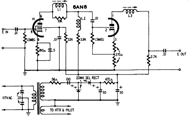
Fig. 917. Schematic diagram of the Chromatic Amplifier. All resistors are
1/2-watt. An interesting feature is the complete absence of any operating controls.
The amplifier provides a gain of approximately 30 times.
The two general test setups used with the probe are shown in Fig. 916. Complete low-frequency information is not obtained in a, because of the limitations in demodulator-probe response.
Complete high-frequency information may not be obtained in b unless the vertical amplifier of the scope has a flat response equal at least to the bandwidth of the chroma circuit under test. Since few service scopes have a flat response out to 4.5 mhz, the technician will usually have to make both tests to obtain complete information.
When the scope being used does not have as good a frequency response as the circuit under test, the result is distortion and attenuation of the curve at the high-frequency end. If the scope has full frequency response, either test is equally useful to deter mine the high-frequency response.
It may not be necessary to use a low-capacitance probe, if the scope is applied across a low-impedance circuit point; but the probe is essential if the scope is applied across a medium or high-impedance circuit point. Omission of the low-capacitance probe in such cases will cause substantial high-frequency attenuation.
Chromatic amplifier

Fig. 918. It is sometimes desirable to boost the signal level to the scope
when testing in very low-gain circuits. Use the amplifier between the receiver
and the demodulator probe as shown.
Fig. 919. Test setup for checking flatness of video sweep output from the Chromatic Probe. In this application the amplifier operates also as a filter.
Sometimes, when working in low gain circuits, you will find the deflection on the scope screen inadequate. In such cases the amplifier circuit shown in Fig. 917 can be used. The amplifier is very simple, with no adjustable controls. It is operated by plugging the amplifier unit into the power line and turning the panel switch to the on position. Instead of applying the demodulator probe directly to the receiver circuits, the amplifier 1s interposed, as shown in Fig. 918. A gain of 30 1s developed by the amplifier over a band of 4 mhz. The output is flat within ±0.5 db from 8 khz to 4 mhz. The input impedance is high and the output impedance is approximately 2,200 ohms.
All resistors in the amplifier are ½ watt, 10 %. L1, L2 and L3 are peaking coils. Their function here is similar to that of similar peaking coils in the video amplifier of a TV receiver namely, to insure wide-band response. L1 and L3 have a range of 102 to 212 µh while L2 is fixed at 93 µh. The power supply uses a voltage-doubler circuit, developing a plate-supply voltage of about 250. Low plate-supply voltage can result from aging of the electrolytic capacitors or the selenium rectifiers.
The amplifier pentode is series-shunt-peaked, and the triode is series-peaked, with negative feedback in the cathode circuit.
The triode grid leak is connected to the midpoint of the feedback resistor to obtain the proper operating point. The series peaking coil of the pentode is damped to flatten the frequency response and avoid excessive high-frequency peaking. However, the series peaking coil of the triode section is undamped because of the lower plate resistance of the triode.
The series peaking coils have adjustable cores to permit equalizing of the frequency response in case the 6AN8 is replaced.
They also compensate for slight tolerances in the factory wiring.
By slight stagger-peaking for a 4 -mhz rise, the over-all frequency response is flat within ± ½ db to 4.5 mhz.
The frequency characteristic of the pentode section depends substantially upon the value of the plate-load resistor (nominally 3,900 ohms). If the high-frequency response becomes abnormally high or low, the value of this resistor should be checked.
The test setup shown in Fig. 919 is very useful for checking the flatness of the video sweep from the Chromatic Probe. If the sweep is flat, the sweep trace appears as shown in Fig. 920. If the sweep trace is not flat within +- 5%, there is some fault in the equipment arrangement which should be corrected before proceeding with service tests.
Fig. 921 shows a similar test setup which is used to check the flatness of the sweep output from the Chromatic Probe when loaded by the input circuit of the receiver under test. There should be no variation from flatness in the sweep trace when this test is made. If there is excessive capacitance across the input circuit of the receiver under test, high frequencies will be attenuated. Normally, this will not happen.

Fig. 920. Appearance of sweep trace when out put from Chromatic Probe is flat.
There may be a slight high-frequency rise, as indicated by the dashed line.
This does not exceed 1/2 db.
After you have determined that the sweep input voltage to the receiver is flat, connect the amplifier as shown in Fig. 922 to observe the response of a video-frequency circuit in the receiver under test.
A shielded cable can be used with the amplifier for making connections to all low-impedance points in a color TV chassis.
A shielded cable has a value of shunt capacitance sufficient to affect the high-frequency response of high-impedance circuits.
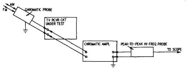
Fig. 921. Use of the amplifier to test the flatness of the sweep out put from
the Chromatic Probe when loaded by the input circuit of the receiver under
test.
Most sweep tests in color TV receivers are made with the signal take-off point chosen at a low-impedance point, such as at the cathode of a phase-splitter tube.
However, you may encounter situations in which the signal take-off point is in a relatively high-impedance, circuit, such as 5,000, 10,000 or more ohms. In such cases it is impractical to use a shielded input cable to the Chromatic Amplifier. Instead, use a pair of open test leads to minimize the shunt capacitance. Open test leads are avoided when possible because there is greater tendency for such leads to pick up stray voltages, such as horizontal and vertical sweep pulses.
Whenever interference from sweep circuits is excessive, you can avoid the difficulty by removing the sweep output tubes. In case the power supply voltage rises excessively upon removal of the tubes, you can put a dummy resistor load across the output of the power supply.
Fig. 922. Typical arrangement of Chromatic Probe, Chromatic Amplifier, and peak-to-peak high-frequency probe in testing a low-gain color-TV video frequency circuit.
In many tests, the use of the amplifier is not necessary, but you will need it in the testing of some low-gain circuits in color TV. Typical low-gain circuits are the chroma amplifier and the I demodulator circuits. The Y amplifier is also a low-gain amplifier but is infrequently checked by sweep methods because of the strong ringing of the delay line.
When a very low-resistance load is shunted across the Chromatic Probe, it may sometimes be observed that the high-frequency response tends to rise somewhat when checking the flatness of the sweep input voltage. In such case, the high-frequency response can be flattened by inserting a small series resistance of 100 ohms or more between the output of the Chromatic Probe and the input of the receiver under test. In rare instances, the nature of the load on the Chromatic Probe will be such that the low frequency response will tend to rise; in such case, a series capacitor of suitable value will serve to flatten the low-frequency response.
Color circuit checks
The Chromatic Amplifier does not have to be used in all color receiver circuit checks. When the circuit under test provides some gain, rather than loss, the amplifier becomes superfluous; for ex ample, tests of the red, blue and green video amplifiers do not require signal boost. However, tests of the Y channel or the matrix elements require amplification to obtain full-screen deflection (unless a very substantial input signal or a very high-gain scope is used). Using the amplifier Fig. 923 shows the three possible arrangements for an amplifier when used to boost the signal into or out of a circuit under test or out of a probe to obtain full-screen deflection on a low-gain scope or for testing a very low-gain circuit. Fig. 923-a is satisfactory from the standpoint of operating stability, but is more costly be cause the amplifier must work into a different circuit impedance for each test. Circuit impedances may vary from that of a 500-ohm contrast control to the grid circuit of the chroma amplifier. The shunt capacitance values in such circuits vary considerably.
Hence, if this method is used, a second tube is required in the amplifier so that a very low output impedance (such as 75 ohms) can be obtained. However, the use of an extra tube should be avoided if another method will prove more practical.
The second arrangement (Fig. 923-b) offers a very attractive feature in that the amplifier may now work into a constant load impedance; the input impedance of the probe. If the specified probe is used with the amplifier, a pentode-triode will develop the desired gain with response flat within + ½ db over the range of 8 khz to 4.5 me in all tests.
Fig. 923-a,-b,-c. In the drawings above we have three possible arrangements of the Chromatic Amplifier.
Bounce
Placing the amplifier between probe and scope might make it possible to use a relatively narrow-band amplifier, requiring one less section in the tube envelope. This arrangement (Fig. 923-c), however, is not practical for service work. Although the amplifier need not have a frequency response above 50 khz for the intended purpose, the low-frequency response of the amplifier must be extended to 20 cycles because a demodulated signal is now being amplified. With a low-frequency response of this type, "bounce" becomes a severe problem since any small variation of line voltage, such as is caused by snapping a light switch on or off, causes the pattern to bounce off-screen. The difficulty can be avoided by operating the receiver under test from an automatic line-voltage regulating transformer. Service shops do not commonly have this type of transformer available for bench work, so the arrangement shown in Fig. 923-b represents the most economical method for the service bench.
The amplifier does not respond to changes in source impedance, thus the input voltage from the circuit under test may be obtained from a low-impedance source such as the cathode of a phase-splitter tube or from a high-impedance one such as the grid of a picture tube, without disturbing the amplifier response. However, the input capacitance of the amplifier is important to the circuit under test since unsuitable test leads may shunt so much capacitance across a high-impedance TV circuit that its operation is disturbed and a distorted response curve obtained.
Effect of shielded cable
A shielded input cable has much more capacitance than does a pair of open test leads, but it is effective in minimizing the possibility of stray field pickup such as flyback pulses. Whenever a shielded cable is to be used in a high-impedance circuit, the possibility of circuit loading must be kept in mind. It is better to "kill" the horizontal sweep section of the receiver and use a pair of open test leads rather than take the chance of disturbing the normal operation of a high-impedance circuit with a shielded cable. Fortunately the majority of signal takeoff points in a color TV chassis can be obtained at low-impedance circuit points.
Bandwidth of scope
The present trend is toward the use of wide-band scopes that provide full gain at the color subcarrier frequency, and of course the gain of such scopes is relatively low. When such a scope is used for alignment work, the Chromatic Amplifier will be required for a greater number of tests. Some wideband scopes, however, provide a dual band arrangement, so that the input circuit can be converted by switching for high-gain narrow-band response. In such case, alignment checks can be made in the high gain position of the switch, and the Chromatic Amplifier will be called upon less often to boost the test signal.
AMAZON multi-meters discounts AMAZON oscilloscope discounts