AMAZON multi-meters discounts
AMAZON oscilloscope discounts
IN the mass of circuits and data that appeared during the earliest I years of the transistor's existence, the amateur radio operator found very little of direct use in his activities. This situation is changing, however, as new circuits are developed and as higher-frequency and higher-power transistors become available.
This section describes several circuits of interest chiefly to the radio amateur. Elsewhere in this guide are other circuits also of interest to the ham but which fall logically into other sections. Examples of these are 50- khz If Amplifier ( Section 2) ; Code-Practice Oscillators, 100- khz Standard-Frequency Oscillators, High-Frequency Crystal Oscillator, Wide-Band Rf Oscillator ( Section 4) ;
All-Wave Regenerative Receiver ( Section 6) ; Sensitive Rf Re lays, Sound-Operated Relay, Carrier-Failure Alarm ( Section 8) and many of the instrument circuits in Section 9.
Keying monitor
Fig. 1001 shows a simple monitor circuit for making CW signals audible to the transmitting operator. This monitor consists of an audio oscillator feeding a pair of headphones and operated from direct current obtained by rectifying the rf carrier picked up from the transmitter. No battery is needed. As long as the transmitting key is held down, rf is present, the transistor receives a dc operating voltage and a tone is heard in the headphones. In this way, the transmitted dots and dashes may be monitored.
The rf is picked up by the small pickup coil L which is placed near the final tank coil in the transmitter and is rectified by the 1N34A germanium diode. Rectified dc passes through the choke coil of a radio-frequency filter (C1-RFC-C2) and through the high-impedance winding of transformer T and the headphones in series to bias the collector of the p-n-p transistor (Raytheon CK722) negative.
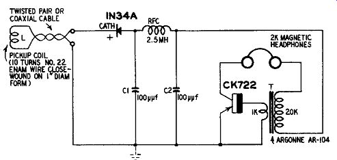
Fig. 1001. Keying monitor.
The oscillator circuit is a simple tickler-feedback arrangement with transformer T providing the regenerative feedback and also the impedance match between the high-impedance collector and low-impedance base. The transformer connections must be phased correctly for positive feedback, otherwise the circuit will not oscillate. If oscillation is not obtained readily, reverse the connections of either the primary or secondary winding of the transformer. The audio tone frequency will be approximately 2,000 cycles. It may be lowered, if desired, by connecting a capacitor in parallel with the 20,000-ohm winding.
Phone monitor
A simple diode detector connected to magnetic phones and rf pickup coil makes a convenient setup for the aural monitoring of radiophone signals. But the sensitivity of this combination is so low that the pickup coil must be coupled tightly to the transmitter, a practice that is dangerous both to the diode and the operator.
When an audio amplifier is added to the detector, the pickup coil may be removed to a safe distance from the transmitter circuit and, at the same time, the headphone signal is boosted. Fig. 1002 shows a phone monitor comprising a diode detector and two-stage transistor amplifier.
In this arrangement, the 1N34A diode acts as a demodulator.
Its output develops an audio-frequency voltage across load resistor R1 which is bypassed for rf by capacitor C1. This of energy is coupled through capacitor C2 to the first transistor. The first stage is direct-coupled to the second stage. Although direct coupling is employed, single-battery operation is made possible by the use of an n-p-n transistor (General Electric 2N170) in one stage and a p-n-p (General Electric 2N107) in the other.
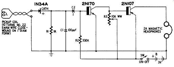
Fig. 1002. Phone monitor.
Speaker-type dynamic microphone
Fig. 1003 shows how a single-stage transistor amplifier may be used with a small PM dynamic loudspeaker to convert the latter in to an inexpensive dynamic microphone with increased output. The complete amplifier may be built small enough to be mounted on the back of the speaker frame.
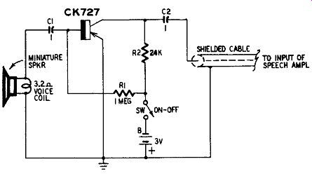
Fig. 1003. Speaker-type dynamic microphone.
Since this device is to be operated into the speech amplifier of a transmitter, its own noise level must be low. A low-noise type of transistor (Raytheon CK727) accordingly is used.
The battery drain is quite low (75 p.a. dc), so two 1.5-volt penlight cells connected in series as battery B will bias the transistor adequately. Mercury cells provide slightly less than 3 volts but maintain their voltage throughout their service life.
Any size of loudspeaker is permissible in this device. The best voice quality will be obtained with the larger diameters. In most instances, however, size requirements will limit the choice to the 4- or 5-inch size.
Signal peaker (CW filter)
Fig. 1004 shows the circuit of a peaked (bandpass) audio amplifier for increased selectivity in cw reception. The center response frequency is 1,000 cycles but may be shifted several hundred cycles above or below this figure by adjustment of the tuning screw of inductor L (UTC type V1C-15) .
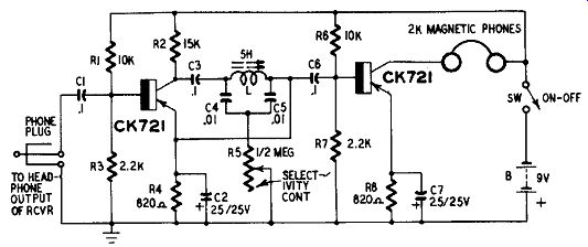
Fig. 1004. Signal peaker (CW filter).
The amplifier consists of two stages, each employing a Raytheon CK721 transistor. In the first stage, a bridged-T null network (C4 C5-L-R5) is connected as a negative feedback filter from the collector-output circuit back to the base-input circuit. This filter may be adjusted for sharp rejection of one frequency by varying the inductance of L and the resistance of R5. This suppresses one frequency from the feedback energy. The result is that the negative feedback cancels the first-stage gain on all frequencies but this one which is readily amplified.
The second stage serves the dual purpose of isolating the filter from the headphone output circuit and of providing power gain for the headphones.
To tune the amplifier initially: (1) Close switch SW. (2) Connect the input phone plug to the output of an audio oscillator set to 1,000 cycles. (3) Connect an ac vacuum-tube voltmeter in parallel with the headphones. (4) Using an Allen wrench, adjust the tuning screw of inductor L for peak deflection of the vtvm. (5) Adjust potentiometer R5 for a sharper and higher-amplitude peak and read just L. Reduce the output of the audio oscillator if the amplifier blocks (as evidenced by mushy headphone signals and sluggish operation of the meter) .
When the circuit is being used, adjustment of R5 gives a degree of selectivity control, allowing the response to be broadened slightly to prevent ringing of the signal.
Field-strength meter
The field-strength meter circuit shown in Fig. 1005 covers the frequency range 1.8 to 68 me in 5 bands: 1.8-4, 3.8-8.6, 8-18, 15-34 and 30-68. The first of these includes amateur 160 and 80; the second, amateur 40; the third, amateur 20; the fourth, amateur 10, 11 and 15; and the fifth, amateur 6 meters. Plug-in coils are used.
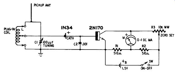
Fig. 1005. Field-strength meter.
General coverage tuning, rather than bandspread, has been employed, since this allows the instrument to be used for harmonic checking in transmitters, antennas and in interference tracing.
The instrument employs a single tuned circuit L-C1 operated from a pickup antenna which may be a short rod or whip. All coils are center-tapped for improved impedance match to the diode detector. They are wound on 1-inch-diameter plug-in forms. The coil table supplies winding instructions.
Dc output from the 1N34A diode detector is applied to the base emitter input circuit of the transistor (General Electric 2N170) with the transistor base positive. The transistor provides dc amplification with a gain of approximately 15. The collector-current increase due to application of the input signal deflects the 0-1 dc milliammeter M. A bridge-type zero-set circuit is provided for the meter.
When using the field-strength meter do not close switch SW until a coil is plugged in. The reason for this precaution is that the base input circuit is open when the coil is removed and this can cause violent deflection of the meter.

------------ Table 10-Coil Table for Field-Strength Meter
Coil A
57 turns No. 32 enameled wire closewound on 1-inch-diameter plug-in form.
1.8-4 mhz
Tap 28th turn from ground end.
Coil B
25 turns No. 26 enameled wire on 1-inch-diame ter plug-in form. Space to winding length of 1/2 inch. Tap 12th turn from ground end.
3.8-8.6 mhz
Coil C
12 turns No. 22 enameled wire on 1-inch-diameter plug-in form. Space to winding length of 1/2 inch. Tap 6th turn from ground end.
8-18 mhz
Coil D
5 1/2 turns No. 22 enameled wire on 1-inch-diameter plug-in form. Space to winding length of 1/4 inch. Tap 11/2 turns from ground end.
15-34 mhz
Coil E
2 1/2 turns No. 22 enameled wire on 1-inch-diameter plug-in form. Space to winding length of 1/4 inch. Tap 1 1/2 turns from ground end.
30-68 mhz
---------------------
Modulation monitor
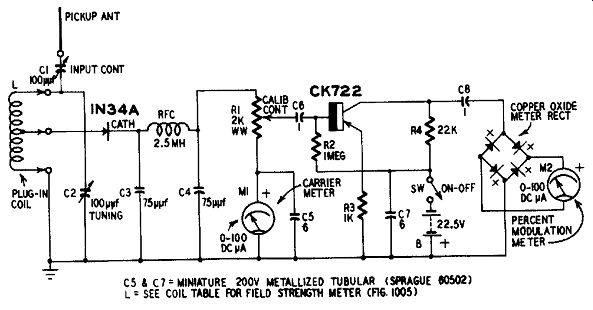
Fig. 1006. Modulation monitor. C5 and C7 = MINIATURE 200V METALLIZED TUBULAR
(SPRAGUE 00502); L = SEE COIL TABLE FOR FIELD STRENGTH METER (fig 1005)
Fig. 1006 shows the circuit of an amplitude-modulation monitor possessing sufficient input-signal sensitivity to permit its operation at a distance from the transmitter. This removes the necessity for dangerous close coupling to the transmitter tank circuit. An important feature of this instrument is that it uses no transformers.
The single tuned circuit (L-C2) is identical with the one employed in the field-strength meter previously described, and coil-winding data may be obtained from the coil table for it. An additional variable capacitor C1 is provided for adjusting the amplitude of the rf input signal.
The dc output of the 1N34A diode rectifier passes through the choke coil of the radio-frequency 1 is proportional to the average amplitude of the carrier component of the AM signal. This deflection is adjusted exactly to full scale by means of variable capacitor C1.
The audio-frequency component (modulation envelope) of the AM signal develops an audio voltage across RI and this voltage is presented to the transistor af amplifier (Raytheon CK722) through capacitor C6. The output signal of the amplifier deflects an audio voltmeter comprised of the copper oxide rectifier RECT and the 0-100 dc microammeter M2.
At any modulation percentage level, there is a corresponding ratio between the carrier and envelope amplitudes. At 100% modulation, for example, both amplitudes are equal. That is, when 100 µa flows through R1 and is indicated by M1, an af drop of 0.2 volt peak is developed across R1. This is because the ac and dc components are equal. This af voltage is amplified by the transistor and deflects meter M2. The deflection of M2 may be set to full scale (100% modulation) by adjustment of R1 . The scale of M2 is calibrated to read directly in PERCENT MODULATION.
The procedure in using the calibrated instrument is to tune in the signal by adjustment of C2 (with the proper plug-in coil L in place) , then to adjust the deflection of the carrier meter M1 to full scale by adjustment of C1, and finally to read the modulation percentage from the percent modulation meter M2. Potentiometer R1 is set during the initial calibration and is not disturbed during normal use of the instrument.
Since the response of meter M2 is not linear at the low signal levels involved, the initial calibration of the instrument is best performed with the aid of an rf oscillator or signal generator having an adjust able amplitude-modulation percentage (0-100%) measured either with an oscilloscope or another calibrated modulation meter. The generator must be connected to the antenna and ground input terminals of the instrument. First set the generator for 100% modulation. Then tune in on peak the modulated signal by adjusting tuning capacitor C2. Next, adjust C1 for full-scale deflection of meter M1. Finally, adjust R1 for full-scale deflection of meter M2.
From this point on, do not disturb the setting of RI. Make additional checks at 90%, 80%, 70%, 60%, 50%, 40%, 30%, 20%, 10% and at as, many intermediate points as possible. At each of these modulation percentage levels, readjust C1, if necessary, for full-scale deflection of MI and note the reading of M2. After a complete calibration run, a meter card reading in percent modulation may be prepared for meter M2 or a graph drawn for this instrument.
CW transmitter
The CW telegraph transmitter circuit shown in Fig. 1007-a has an rf output of only 27 mw but under favorable conditions it can give good account of itself.
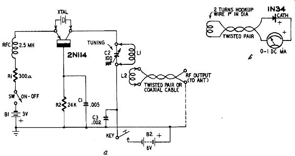
Fig. 1007-a,-b. CW transmitter.
The circuit is that of a simple 80- and 160-meter crystal oscillator employing an rf transistor (Raytheon 2N114) . Two batteries are used: 3 volts (BI) for emitter bias and 6 volts (B2) for the collector. The current drain from each is approximately 10 ma.
Baby-type, commercial, end-link, plug-in transmitter coils ( L1 L2) are employed. In each instance, L2 is the link coil. The 80-meter coil pair is a Barker & Williamson MEL-80 and the 160-meter pair a Barker & Williamson MEL-160. Low-impedance output (50 to 75 ohms) is provided for coupling to an antenna coupler or directly to the center of a dipole antenna.
Tuning in the conventional manner with a dc milliammeter in the oscillator circuit is not practicable with a transistorized oscillator. For tuning purposes, a crystal-type meter is shown in Fig. 1007-b. The small two-turn pickup coil is held close to coil L1 of the transmitter, and capacitor C2 turned for peak deflection of the 0-1 dc milliammeter.
Conelrad receiver
Fig. 1008 shows the circuit of a versatile receiver for Conelrad compliance. This receiver gives visual and aural indications and will operate a signal alarm. The circuit comprises a broadcast-band bandpass tuner, diode detector, two-stage dc amplifier, indicating meter and sensitive relay. Deflection of the 0-1 dc milliammeter M indicates the presence of the station carrier. Relay RY also is held in as long as the carrier is present. The station may be monitored aurally by means of headphones plugged into jack J. When the carrier is interrupted, the meter returns to zero and the relay drops out. The relay will operate a normally-closed relay in an external alarm device, such as a bell or horn circuit.
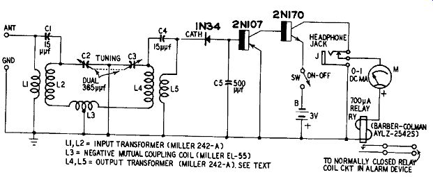
Fig. 1008. Conelrad receiver.
A bandpass tuner is employed since this gives maximum selectivity with diode detection. The tuner consists of the dual 36540 variable capacitor C2-C3, two radio-frequency transformers L1-L2 and L4-L5 and the negative mutual coupling coil L3. Transformer L1-L2 is connected in the normal manner with the low-impedance winding L1 as the primary. To match the low impedance of the 1N34 diode, however, the second transformer L4-L5 is connected into the circuit backward. That is, the low-impedance winding L5 is used as the secondary.
Dc output of the diode is amplified by the direct-coupled amplifier and actuates milli-ammeter M and relay RY in series. The first stage transistor is a p-n-p unit (General Electric 2N107) , while the second-stage unit is an n-p-n (General Electric 2N170) .
Transistors in conventional amateur receivers
There are numerous points in standard, tube-type amateur receiver circuits where transistorized sub-circuitry might be employed to advantage. Examples are: signal peakers, Q5ers, noise silencers, signal-strength indicators, received-signal modulation monitors, Q-multipliers, etc. which can be self-powered when transistorized and therefore place no added burden on the receiver power supply.
The amateur with experimental bent will find both education and diversion in transistorizing devices of this sort from their original tube circuits. Respectable power supply economies may be obtained by transistorizing as much as possible of the circuitry, especially in portable receivers.