AMAZON multi-meters discounts
AMAZON oscilloscope discounts
BATTERY-OPERATED electronic test instruments offer the advantages B of complete freedom from the power line, circuit simplicity and heat-free operation. Self-power minimizes the interaction and stray coupling which often occur between separate pieces of line operated equipment and removes the instrument hum problem.
Operation from batteries also makes completely portable operation practicable.
Heretofore, however, it has not been prudent to employ batteries in many instruments in which their use would have been desirable.
The reason for this is that vacuum tubes impose a comparatively heavy load on small batteries, resulting in short battery life. If a battery-operated instrument were left switched on accidentally during idle periods, an expensive set of batteries would be destroyed quickly. Such operation of course is uneconomical. Coupled to this disadvantage is the necessity in tube circuits of both an A and B battery, a factor which increases circuit complexity as well as initial and replacement costs.
The low current requirements of the transistor and its ability to operate at dc voltages easily supplied by inexpensive flashlight cells fit the transistor for use in test instruments. Even when a standard B battery must be used in a transistorized instrument circuit, it may be expected to give up to several hundred times its normal service life in an equivalent tube circuit. The current drain in some transistorized instruments is so low that the instrument might be left running continuously for several months without harming the battery. Thus, the accidental on-time hazard is removed. For this reason, some experimenters prefer to omit the ON-OFF switch, there being little point in switching off a battery when its service period will equal its shelf life.
The small size of the transistor and its circuit components permits miniaturization of instruments, an important consideration when the number of devices on the laboratory bench is continually growing.
At this writing, not all well-known instruments may be transistorized successfully.
Further refinement is needed in some of the parameters of commercial transistors and further circuit study is necessary. The day is in sight, however, when all portable test instruments (and perhaps the stationary variety as well) will be transistorized. This section describes some of the circuits which are readily transistorized and may be duplicated with success by the experimenter.
Low-gain single-transistor dc microammete
In Fig. 901, the base-to-collector current amplification factor of the Raytheon CK722 transistor is utilized to convert a 0-1 dc milli-ammeter into a 0-50 dc microammeter. The common-emitter amplifier circuit is employed with the milliammeter as the collector load.
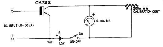
Fig. 901. Low-gain dc microammeter.
Full-scale deflection of the meter is obtained with a dc input of 50 microamperes. The 200-ohm wirewound rheostat R serves as a meter-shunting CALIBRATION control. With an accurately known 50-ma input to the circuit, R is adjusted for exact full-scale deflection of the meter. Response of the circuit is linear; e. g., 0.5-ma deflection indicates an input of 25 µa.
With i_co characteristic of the transistor.
This initial deflection may be suppressed, however, by setting the pointer to zero mechanically with the zero-set screw.
The input resistance of this circuit is approximately 8,000 ohms.
Zero-setting circuits for microammeter
The zero-signal collector current (ic) increases with tempera ture. It very easily can deflect the meter so far upscale that suppression cannot be accomplished with the mechanical zero set of the instrument. This seriously restricts the range and accuracy of the simple microammeter shown in Fig. 901. Zero-setting circuits, similar to those employed in vacuum-tube voltmeters, therefore are desirable in all but the simplest transistorized dc micro-ammeters.
Figs. 902 and 903 show how zero-set circuits may be added to the microammeter. Except for this addition, the microammeter circuit and its operating characteristics remain the same as stated for Fig. 901.
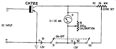
Fig. 902. Battery-type zero-set circuit for microammeter.
In Fig. 902, a second battery (B2) and a 2,000-ohm wirewound rheostat (R2) constitute the zero-set circuit. Current flows from B2 through the milliammeter in the opposite direction to that of ie. and is used to zero the meter by adjustment of R2. The range of the zero-set rheostat has been chosen such that the resistance setting ...
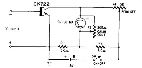
Fig. 903. Bridge-type zero-set circuit for microammeter.
... when the meter is zeroed will be at least 10 times the resistance of the meter and calibration rheostat (R1) in parallel. This insures that the collector-current change, when the circuit is actuated by an input signal, will pass through the meter instead of the zero-set circuit.
The zero-set battery B2 may not be left in the circuit when the instrument is not in use, since it will discharge through R1, R2 and the meter. To disconnect it, a second pair of terminals (S2) has been added to the original ON-OFF switch S1. This resultant dpst switch operates both batteries.
The current drain of the second battery is quite small, not exceeding under any circumstances twice the value encountered.
Nevertheless, it is an extra power supply component and may be regarded as a nuisance by some instrument builders and users. To permit single-battery operation of the entire circuit, a bridge-type zero-set circuit (similar to the one employed in conventional vacuum-tube voltmeters) may be used. This arrangement is shown in Fig. 903.
The four arms of the bridge are R1, R2, R4 and the internal collector-to-emitter resistance Rt of the transistor. The bridge is balanced (meter zeroed) by adjustment of rheostat R4. At null, since R1 and R2 are equal arms: R4 =
This circuit has the convenience of single-battery supply. however, its current drain is higher since a "bleeder" current of 1.47 ma flows continuously through RI and R2 in series as long as the instrument is switched on.
High-gain dc microammeter
There are three ways to increase the sensitivity of the simple low-gain microammeter circuit: (1) substitute a high-alpha transistor, (2) substitute a microammeter for the milliammeter or (3) both (1) and (2) . Only the circuits shown in Figs. 902 and 903 are recommended for use with either of these schemes since the higher sensitivity increases the need for electrical zero setting.
Full-scale deflections as low as 20 u-a may be obtained with the 0-1 milliammeter when a high-alpha transistor is used. Examples are Raytheon CK721 (25 ua) , Sylvania 2N34 (35 u-a) and Raytheon CK725 (20 u-a) .
When a dc microammeter is substituted for the milliammeter, rheostat R2 in Fig. 902 must be changed to one having a total resistance equal to at least 10 times the internal resistance of the meter. Also, R1 must have a total resistance equal to 2 times the meter resistance. When a microammeter is substituted in the circuit given in Fig. 903, rheostat R3 must have a total resistance equal to 2 times the internal resistance of the meter and the total resistance of R4 must equal 10 times the meter resistance. Fig. 904 shows a high-gain circuit in which a 0-100 dc microammeter has been substituted for the milliammeter. An n-p-n transistor ( Sylvania 2N35) is employed. Full-scale deflection indicates a dc input of 10 µa. The steady bleeder current through RI and R2 in series is 6.83 ma.
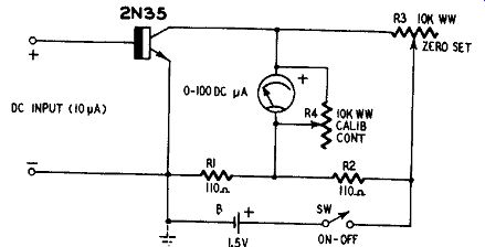
Fig. 904. High-gain dc micro-ammeter.
A large increase in sensitivity is obtained when both the transistor and the indicating meter are changed. For example, a Raytheon CK725 may be used in conjunction with the 0-100 dc microammeter in Fig. 904, provided the polarities of DC INPUT terminals, microammeter and battery all are reversed. A dc input of only 2µa then will give full-scale deflection of the meter.
Supersensitive dc microammeter
Fig. 905 shows the circuit of a two-stage dc microammeter which gives full-scale deflection with 0.5 µa input. This is a direct-coupled dc amplifier circuit in which collector current of the input transistor flows directly into the base-emitter input circuit of the output transistor.
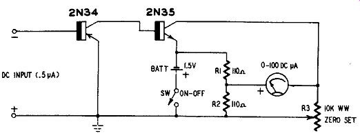
Fig. 905. Supersensitive dc microammeter.
To secure single-battery operation, a p-n-p transistor ( Sylvania 2N34) is used in the first stage and an n-p-n ( Sylvania 2N35) in the second stage. A bridge-type zero-set circuit (R1-R2-R3) is provided.
The steady bleeder current through R1 and R2 in series is 6.83 ma.
Electronic dc voltmeter
A transistorized version of the familiar dc vacuum-tube voltmeter is shown in Fig. 906. Basically, this circuit is a two-stage amplifier-type dc microammeter (0-10 µa) employing a 0-1 dc milliammeter and provided with suitable multiplier resistors to convert it into a multirange voltmeter.
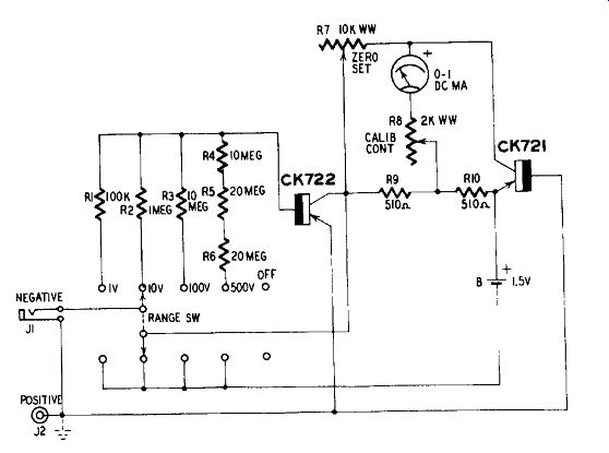
Fig. 906. Electronic dc voltmeter.
The high sensitivity of the microammeter circuit (10 µa full scale) gives this voltmeter a resistance rating of 100,000 ohms-per-volt. On the 100- and 500-volt ranges, it has an input resistance equal to or higher than that of commercial units. The voltage ranges are 0-1, 0-10, 0-100 and 0-500.
The multiplier resistors R1 to R6, must be selected to have the exact specified values. The 50-rnegohm value required for the 500-volt range is obtained by series-connecting one 10- and two 20-meg ohm resistors. While the highest-voltage range (0-500) will be adequate in many applications, a 0-1,000-volt range may be desired as well as various intermediate ranges. Table 5 shows the values for multiplier resistors required for common voltage ranges other than those indicated in Fig. 906.
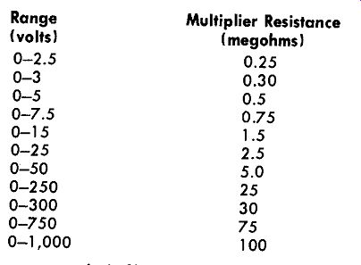
Table 5-Multiplier Resistor Values Range (volts) Multiplier Resistance (megohms)
0-1,000 100
One pole of the RANGE switch disconnects the battery. For protection of the instrument, the OFF position is placed after the highest voltage range.
Phone jack J1 is provided for the "high" dc input lead which in this circuit is connected to the negative terminal of the voltage source under test. This type of jack is employed because the "high" test lead usually is shielded.
The "low" positive lead is connected to pin jack J2.
The microammeter portion of the circuit is similar to the circuit described in the sections immediately preceding this. A direct coupled dc amplifier with two p-n-p transistors (Raytheon CK722 input and Raytheon CK721 output) is used. A bridge-type zero-set circuit is comprised of resistors R7, R9 and R10.
After setting the meter to zero by adjustment of rheostat R7, the instrument is calibrated initially by (1) setting the RANGE switch to its 1-volt position, (2) applying an accurately-known 1-volt potential to the input jacks and (3) adjusting rheostat R8 for exact full-scale deflection.
Audio voltmeter-millivoltmeter
An instrument for measuring audio voltages in the millivolt ranges is convenient for checking gain, small signal amplitudes, noise voltages, etc. Fig. 907 shows a transistorized millivoltmeter circuit.
Ranges provided are 0-10-30-100-300 millivolts and 0-1-3 volts. All are rms values. Higher voltage ranges have not been provided since they require impractically high resistance values in the range selector network. The indicating meter is a 0-100 dc microammeter.
The circuit consists of a five-stage amplifier driving a rectifier-type output voltmeter consisting of microammeter M and the four 1N34 germanium diodes. The input stage of the amplifier uses an emitter-follower circuit for high input impedance. This circuit ordinarily has an input impedance of 1 megohm but this is reduced to 0.5 megohm by the 1-megohm section (R8) of the input voltage divider. The input transistor is a Raytheon CK725 while all others in the circuit are Raytheon CK768's.
The instrument requires no zero adjustment since the meter receives no ac voltage until a signal is applied to the AC INPUT terminals. The only adjustment is the RANGE switch S1. The 25,000-ohm CALIBRATION CONTROL potentiometer R10 needs only occasional adjustment. It should be mounted safely inside the instrument case where its setting will not be disturbed accidentally.
Resistors R1 to R8 constitute the input-signal voltage-divider string and must have the exact specified values. Aerovox precision Carbo-film resistors are obtainable in the resistance values shown in Fig. 907, with an accuracy ± 1%.
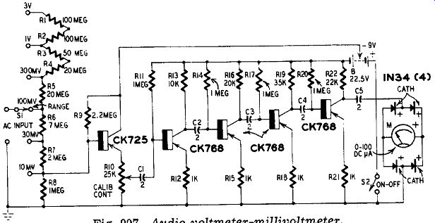
Fig. 907. Audio voltmeter-millivoltmeter.
To calibrate the instrument initially: (1) Close switch S2. (2) Set RANGE SWITCH S1 to its 1-volt range. (3) Apply an accurately known 1-volt rms, 1,000-cycle signal to the AC INPUT terminals. (4) Adjust CALIBRATION control R10 for exact full-scale deflection of the microammeter. (5) Check the deflection at 0.1, 0.2, 0.3, 0.4, 0.5, 0.6, 0.7, 0.8 and 0.9 volt input and at as many intermediate voltage points as possible. (6) Change RANGE switch Si to its 3-volt position. A 3-volt input signal now must be applied to the input terminals and should deflect the meter to full scale. (7) Check the deflection at 0.5, 1, 1.5, 2 and 2.5 volts and at as many intermediate voltage points as possible. (8) From the data obtained in steps 4, 5, 6 and 7 prepare a special card for the meter, with one scale graduated from zero to 1 and the other from zero to 3.
The instrument finally should be checked for accuracy through out the frequency range from 50 cycles to 20 khz. Response falls off rapidly at frequencies higher than 20 khz.
Millivolt adaptor for ac vacuum-tube voltmeter
The lowest range of conventional ac vacuum-tube voltmeters usually is 1.5 volts. Many of the older instruments go no lower than 3 volts full scale. Fig. 908 shows the circuit of a simple adaptor which may be used as a probe ahead of an ac vacuum-tube volt meter to convert it into a millivoltmeter. The adaptor increases the meter sensitivity 100 times, converting the 1.5-volt range to 0-15 my and the 3-volt range to 0-30 mv.
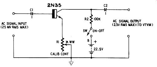
Fig. 908. Millivolt adaptor for ac vtvm.
The adaptor is a single-stage common-emitter amplifier employing a Sylvania 2N35 transistor. The high input impedance of 25,000 ohms is made possible by the large amount of degeneration introduced by the unbypassed emitter resistor R1 which serves also as the calibration control. The maximum input-signal voltage before severe output distortion is 25 mv rms. The corresponding maximum output is 2.5 volts rms. The adaptor output must be applied to a high-impedance load such as the input circuit of a vtvm or oscilloscope. The minimum permissible load resistance, for full utilization of the voltage gain of the adaptor, is 1 megohm.
To calibrate the adaptor initially: (1) Connect an ac vacuum-tube voltmeter to the AC SIGNAL OUTPUT terminals. (2) Apply an accurately known 10-mv rms, 1,000-cycle signal to the AC SIGNAL INPUT terminals. (3) Set the CALIBRATION CONTROL rheostat R1 for 1-volt deflection of the vtvm.
Sensitizer for high-range dc milliammeter
The base-to-collector current amplification of a power transistor (CBS 2N55) is utilized in the circuit shown in Fig. 909 to boost the sensitivity of a high-range dc milliammeter. The circuit is shown connected to a 0-10 milliammeter which it converts into a 0-0.5 dc milliammeter (0-500 microamperes) . The input-signal voltage is 200 mv dc.
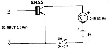
Fig. 909. Sensitizer for high-range de milliammeter.
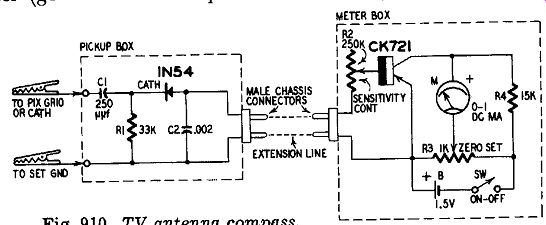
Fig. 910. TV antenna compass. This same scheme may be used to convert a 0-50
dc milliammeter to a 0-2.5 ma, a 0-100 ma to a 0-5 ma, or a 0-1-ampere instrument
to 0-50 ma. A heat radiator (based upon 6 x 6 x 1/8-inch aluminum base) must
be used when 1 ampere of collector current is to be handled.
TV antenna compass
The conventional compass used in the orientation of TV antennas for maximum signal pickup consists of a diode-type rf volt meter (germanium diode plus current meter). The current meter is placed on the roof in clear view of the antenna technician while the diode is connected to the receiver and feeds the meter through a long extension line. The diode is capacitance-coupled to the picture-tube grid or cathode, depending upon which element receives the output of the video amplifier.
The current meter usually is a sensitive dc microammeter. It can be both expensive and delicate. A single-stage transistorized dc amplifier makes it possible to use instead a 0-1 dc milliammeter in the compass and, at the same time, to obtain greater sensitivity than is afforded by the microammeter. Fig. 910 shows the circuit of the transistorized compass.
The pickup box is placed at the receiver. Crocodile clips permit connection to the picture tube and to receiver ground. The detector diode (Sylvania I N54) is capacitance-coupled through C1 to protect it from any dc component coming from the receiver. Dc output from the diode passes through a two-wire extension line (which may be ordinary rubber-covered electric cord) to the meter box on the roof.
The meter box contains, in addition to the 0-1 dc milliammeter M, the dc amplifier built around the p-n-p transistor (Raytheon CK721). The base rheostat R2 serves as the SENSITIVITY control, while potentiometer R3 is the ZERO-SET control in the collector bridge circuit.
The instrument requires no calibration since it is used only as a peak indicator. The antenna is rotated for maximum deflection of meter M. If the pointer is driven off scale by a strong signal, the sensitivity of the circuit must be reduced by resetting R2.
TV field-strength meter
Fig. 911 shows the circuit of a field-strength meter which may be used to measure the intensity of signals picked up by an antenna or as a highly sensitive TV antenna compass. The single tuning range of this instrument extends from 40 to 226 megacycles, covering all television channels and the various frequencies, amateur and commercial, between these frequency limits.
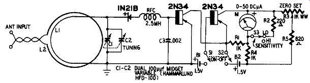
Fig. 911. TV field-strength meter.
The instrument circuit includes a tuner (L1-L2-C1-C2) , a detector employing a silicon point-contact diode (Sylvania 1N21B) for improved high-frequency performance, a two-stage dc amplifier (Sylvania 2N34's) which builds up the feeble dc output of the diode sufficiently to deflect the 0-50 dc microammeter M, and a bridge-type zero-set circuit (R1-R3-R4-R5) . The meter shunt resistor R2 reduces the sensitivity of the circuit when the SENSITIVITY switch S3 is thrown to its LO position. When S3 is in its HI position, an rf signal voltage of 1 mv will produce the smallest readable deflection of the meter.
The main coil of the tuner consists of a hairpin loop L1 made with No. 20 bare tinned copper wire. Fig. 912-a shows its dimensions. This coil is tuned by a 200-u-f midget variable capacitor. A satisfactory 200-uuf capacitor free from self-resonance within the tuning range of the field-strength meter could not be obtained. A dual 100-uuf unit (C1-C2) accordingly has been used with its two sections connected in parallel by a short straight piece of No. 20 bare wire. The antenna coupling coil L2 is a single 0.75-inch-diameter turn of insulated hookup wire, made as shown in Fig. 912-b and mounted 1 /16 inch from L1 (Fig. 911) .
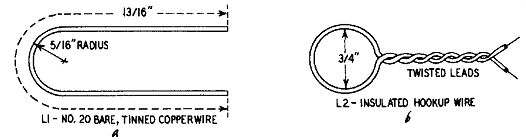
Fig. 912-a,-b. Details of field-strength meter coils.
The SENSITI VITY switch S3 shunts the microammeter with a 220-ohm resistor R2 to change the meter deflection by approximately 10. Cutting this resistor into the circuit disturbs the zero setting of the meter by less than 1% of full scale (one small scale division).
When S3 is set to its HI position, any random fluctuation of the meter pointer due to transistor noise is less than one-quarter of a small scale division.
With switch S3 at its Fti position, battery B1 delivers 18 u-a and B2 1.6 ma when an rf input signal deflects meter M to full scale.
With S3 set to Lo, B1 delivers 30 u-a and B2 2 ma. These low current drains make operation from flashlight cells entirely feasible.
The best frequency-calibrating source will be an accurate rf signal generator covering tht, range of 38 to 230 mhz, preferably on fundamental frequencies all the way. This instrument should be a standard oscillator (either modulated or unmodulated) but not a sweep generator. The generator output is connected to the ANTENNA INPUT terminals of the field-strength meter. If the generator has an output control (attenuator) calibrated in microvolts, it may be used to calibrate the scale of the microammeter in micro volts or millivolts.
In this field-strength meter, the microammeter response is approximately square-law due to the shape of the conduction curve of the crystal diode at the low signal amplitudes involved.
If the meter is to be used exclusively for television, the C1-C2 dial may be graduated conveniently in the TV channel numbers.
The tuner responds separately to the video and sound frequencies.
The former are recommended for the dial marking. For this purpose, the following table shows the video carrier frequencies corresponding to the various channel numbers.
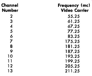
Table 6-Video Carrier Frequencies
Bridge null detector
An R-C-coupled, high-gain transistor amplifier followed by a rectifier type microammeter makes a compact null detector suit able for impedance bridges. Operated from 6 volts of flashlight battery, this self-contained instrument may be built small enough to be installed inside the bridge.
Fig. 913 shows the circuit of a null detector. By employing a common-collector input stage, the circuit is given an input impedance of 0.25 megohm. This stage is followed by two common emitter stages. The output stage is capacitance-coupled, through C4, to the meter circuit consisting of a miniature bridge-type copper oxide meter rectifier RECT and a 0-50 dc microammeter M.
Single-battery operation is made possible by employing an n-p-n transistor ( Sylvania 2N35) in the common-collector input stage and p-n-p's (Sylvania 2N34) in the two other stages.
When the GAIN CONTROL potentiometer R1 is set for maximum gain, an input signal of 5 millivolts rms will produce full-scale deflection of the meter.
The total drain from the 6-volt battery B is 1.2 ma dc.
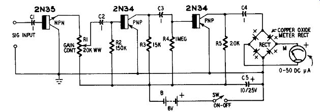
Fig. 913. Bridge null detector.
Sharply tuned null detector Fig. 914-a shows the circuit of a bridge null detector having high selectivity and high input impedance. Like the circuit previously described, it has an input impedance of 0.25 megohm afforded by the common-collector input amplifier stage. Two n-p-n ( Sylvania 2N35) and three p-n-p transistors ( Sylvania 2N34) are employed.
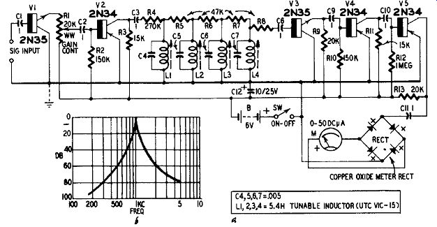
Fig. 914-a,-b. Sharply tuned null detector.
The common-collector stage V1 is followed by a high-gain common emitter V2. The output of the latter is presented to a four-section tunable bandpass filter 4 comprising variable inductors L1, L2, L3 and L4; capacitors C4, C5, C6 and C7 and resistors R4, R5, R6, R7 and R8. The inductors (UTC type V1C-15) are tuned by means of Allen-screwed slugs. A second common-collector stage (V3) follows the filter, the high input impedance of this stage offering negligible loading to the filter. The remaining common emitter stages (V4 and V5) build up the signal to compensate for the attenuation introduced by the filter and to drive the meter circuit (rectifier RECT and the 0-50 dc microammeter M) .
The circuit may be pre-tuned to any bridge operating frequency between 500 and 1,000 cycles. By increasing or decreasing capacitances C4, C5, C6 and C7, other frequency ranges may be obtained.
Fig. 914-b shows the response when the circuit is tuned to 1,000 cycles. Note from this plot that transmission is down 60 db at points one octave on each side of the center frequency. A 5-mv rms input signal at the center frequency will deflect meter M to full scale.
The null detector may be aligned in the following manner:
Connect an audio signal generator to the SIGNAL INPUT terminals and set its output high enough to give quarter-scale deflection of meter M. With the GAIN control RI set for maximum gain, start with L4 and work progressively back to L1, adjusting each inductor for peak deflection of the meter. If at any point in this adjustment the pointer is driven off scale, reduce the setting of the generator output control or of RI or both. Readjust each inductor for sharper peaking.
If the selectivity indicated by Fig. 914-b is too high, the four inductors may be stagger-tuned for a flat-topped response curve.
Crystal-type sound marker generator
Crystal-type marker-pip generators are required for spotting the 4.5- mhz sound-channel point in visual TV alignment since self excited oscillators are not accurate enough for this purpose.
Many early-model TV sweep generators have no provision for crystal marker-circuit operation. In such instances, the crystal oscillator circuit shown in Fig. 915 may be connected externally.
This circuit employs an n-p-n rf transistor ( Sylvania 2N94A) and is resonated by a 9-to-16-mh slug-tuned inductor L (Miller 4506) .
Peak deflection of an rf vacuum-tube voltmeter connected temporarily to the RF OUTPUT terminals will indicate resonance.
Emitter dc bias is supplied by the voltage drop across resistor R2; collector dc bias by the drop across R3. Total current drain from the 7.5-volt battery B is 13 ma dc. The open-circuit rf output of the oscillator is 5 volts rms.
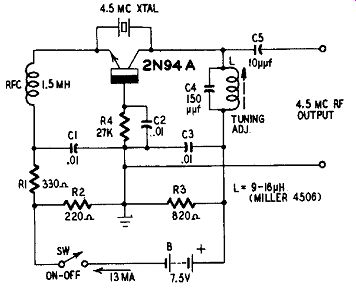
Fig. 915. Crystal-type sound marker generator.
Audio signal injector Fig. 916 shows the circuit of a miniaturized 1,000-cycle oscillator which may be built into a probe handle and used to troubleshoot audio amplifiers by the signal-injection method. A p-n-p transistor ( Sylvania 2N34) is operated from a 1.5-volt penlight cell in this device.
A simple tickler-feedback oscillator circuit is employed. The frequency is determined by the 2,000-ohm winding of transformer T and the capacitance of C 1
The transformer must be phased correctly or oscillation will not be obtained. The simplest procedure is to follow the color coding shown in Fig. 916. The ground connection marked chassis in the wiring diagram is a connection to the metal shell or shield of the probe into which the signal injector is built.
The signal output amplitude is 1 volt peak-to-peak across a load ...
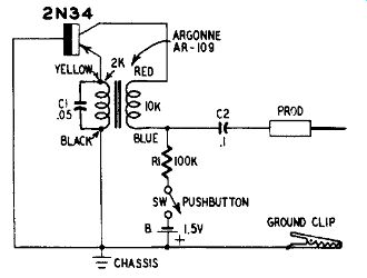
Fig. 916. Audio signal injector.
... resistance of 39,000 ohms. The amplitude drops to 50 millivolts peak-to-peak when the external load is reduced to 1,000 ohms.
When testing sensitive amplifier circuits, it is not necessary to connect directly to the circuit. Merely pointing the prod closely to the test point will couple sufficient signal into the amplifier.
The current drain from the 1.5-volt cell B is 8 µa dc.
Crystal-type set aligner
Crystal oscillators are convenient for spot-frequency alignment of receivers because these oscillators are stable and accurate. however, it is generally thought that a considerable number of crystals is needed for a complete alignment.
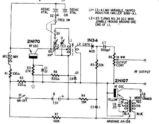
Fig. 917. Crystal-type set aligner.
Fig. 917 shows the circuit of an alignment generator for broad cast receivers, employing only two crystals. The 455- khz crystal, used primarily for if alignment, also furnishes strong harmonics at 910 and 1,365 khz. The 500- khz crystal supplies 500-, 1,000- and 1,500- khz frequencies, the latter two being harmonics. The desired crystal is switched into the circuit by means of the two-pole two-position FREQUENCY switch 82--83.
The collector tank circuit is tuned by trimmer capacitor C2 for 455 khz and by C3 for 500 khz. Both of these are fixed-tuned adjustments. The tank coil L1 is a slug-tuned 1.3- to-4.1-mh inductor (Miller 6199-A) .
When the slug has been set initially in the adjustment of the instrument, it requires no readjustment until the instrument is recalibrated.
The coupling coil L2 is made by jumble-winding 20 turns of No. 24 dcc wire around one end of L1.
The circuit consists of the crystal rf oscillator employing an n-p-n rf transistor (General Electric 2N170) , 1N34 diode modulator and a 1,000-cycle audio oscillator employing a p-n-p transistor (General Electric 2N107) . When switch S4 is set to its UNMOD position, the rf output signal is unmodulated.
The polarity of the 1N34 diode must be followed or this unit will not function correctly as a modulator. The polarity of the feedback transformer T also is important. Follow the transformer color coding shown in Fig. 917, otherwise this circuit will not oscillate. If a modulating frequency lower than 1,000 cycles is desired, increase the capacitance of C6. Two or more modulating frequencies may be accommodated by arranging a switch for cut ting appropriate capacitors into the circuit.
To adjust the instrument: (1) Connect an rf vacuum-tube voltmeter to the RF OUTPUT terminals. (2) Set OUTPUT control R6 for maximum output. (3) Set the FREQUENCY switch S2-S3 to its position A. (4) Screw the slug of inductor L1 about halfway into the coil. (5) Close switch Si. (6) Adjust trimmer C2 for peak deflection of the vtvm. (7) Throw switch S2-S3 to position B and adjust trimmer C3 for peak deflection of the vtvm. (8) If either adjustment (C2 with switch S2-S3 at position A or C3 with S2-S3 at position B) cannot be reached in the tuning range of the capacitor, reset the slug in L1 and repeat. However, this changes the inductance of the coil and both frequency adjustments must be remade.
The modulation may be checked by feeding the rf output signal into a receiver, throwing S4 to its MOD position, tuning the receiver to the aligner carrier frequency and monitoring by ear.
Rf signal generator
Fig. 918 shows the circuit of a general-purpose rf signal generator supplying both CW and amplitude-modulated signals in the range from 440 khz to 30 mhz. The upper frequency is dependent upon the individual characteristics of the rf transistor (Philco SB100) employed in the rf oscillator stage. Some of these transistors will reach 40 or 45 mhz. However, all should attain 30 mhz without difficulty. The frequency range is covered in five switched bands: 440 1,200 khz, 1-3.5 mhz, 3.4-9 mhz, 8-20 mhz and 18-30 mhz. Harmonics of the last band are usable to much higher test frequencies.
A complete coil set (main coil, tickler and output coupling winding) is switched into the circuit each time the band is changed. These coils are selected by means of the four-pole, five-position non-shorting switch (S1-S2-S3-S4) . The SB 100 collector is tapped down the main coil for impedance-matching purposes.
Each main coil is shunted by a 75-Nlf air trimmer capacitor (C4, C5, C6, C7, C8) for use in alignment. The coil table gives winding instructions for the five sets of coils.

------------ Table 7-Coil Table for Rf Signal Generator
Band A 440-1,200 khz Band B 1-3.5 mhz Band C 3.4-9 mhz Band D 8-20 mhz Band E 18-30 mhz
L1: 187 turns No. 32 enameled wire close-wound on 1-inch-diameter form. Tap 90th turn from low end.
L2: 45 turns No. 32 enameled wire close-wound on same form as L1. Space 1/16 inch from top of L1.
L3: 20 turns No. 32 enameled wire close-wound on same form as L1. Space 1/16 inch from bottom of L1.
L4: 65 turns No. 32 enameled wire close-wound on 0.5-inch-diameter form. Tap 33rd turn from lower end.
L5: 15 turns No. 32 enameled wire close-wound on same form as L4. Space 1/16 inch from top of L4.
L6: 8 turns No. 32 enameled wire close-wound on same form as L4. Space 1/16 inch from bottom of L4.
L7: 27 turns No. 26 enameled wire close-wound on 1/2-inch-diameter form. Tap 13th turn from low end.
L8: 8 turns No. 26 enameled wire close-wound on same form as L7. Space 1/16 inch from top of L7.
L9: 5 turns No. 26 enameled wire close-wound on same form as L7. Space 1/16 inch from bottom of L7.
L10: 10 turns No. 22 enameled wire on 0.5-inch-diameter form. Space to winding length of 0.5 inch. Tap 5th turn.
L11: 4 turns No. 22 enameled wire close-wound on same form as L10. Space 1/16 inch from top of L10.
L12: 3 turns No. 22 enameled wire close-wound on same form as L10. Space 1/16 inch from bottom of L10.
L13: 51/2 turns No. 22 enameled wire air-wound 1/2-inch in diameter. Space to winding length of 1/2 inch. Tap 3rd turn from low end.
L14: 4 turns No. 22 enameled wire air-wound, closewound 1/2 inch in diameter. Mount 1/16 inch from top of L13.
L15: 3 turns No. 22 enameled wire air-wound, closewound 1/2 inch in diameter. Mount 1/16 inch from bottom of L13.
-------------------------
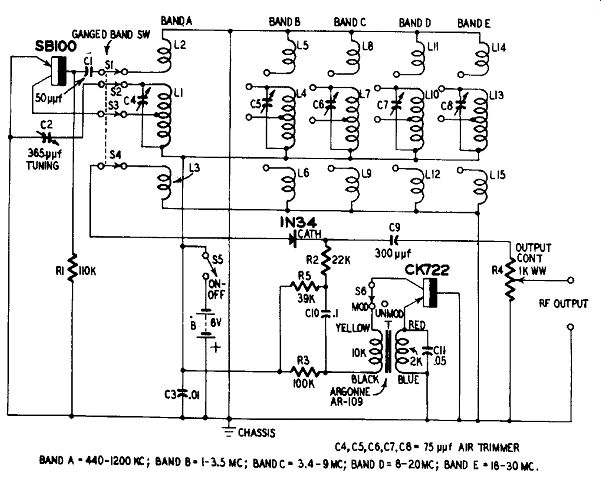
Fig. 918. Rf signal generator.
A 1N34 diode modulator is used and is driven by a 1,000-cycle audio oscillator employing a p-n-p transistor (Raytheon CK722) .
Lower modulating frequencies may be obtained by increasing the capacitance C 11. Switch S6 in the af oscillator circuit is the modulation selector. When it is thrown to its UNMOD position, the rf output signal is unmodulated. The correct poling of transformer T is essential, otherwise the af stage will not oscillate. Follow the color coding shown for this transformer in Fig. 918. Mount the transformer so that it is not in the fields of the rf coils.
The signal generator may be aligned initially by the conventional method, using another accurately-calibrated rf signal generator or a frequency standard. Each coil set must be peaked (by means of C4, C5, C6, C7 or C8) with tuning capacitor C2 set to its top-of-band point.
Radio-frequency comparator
An untuned heterodyne detector is useful for comparing aurally two rf signals, one usually being of unknown frequency and the other known. A germanium diode is convenient for the purpose but its audio output is so feeble when the rf amplitude is low that that zero-beat identification becomes difficult.
Fig. 919 shows the circuit of a diode type heterodyne detector to which has been added a two-stage audio amplifier. Simplified direct coupling between amplifier stages has been made possible by the use of an n-p-n transistor (General Electric 2N170) in the first stage and a p-n-p (General Electric 2N107) in the second.
The two rf input signals are presented simultaneously (through RF INPUT 1 and RF INPUT 2) to the 1N34 detector. Capacitance coupling, through C1 and C2, blocks any dc component which might be present in the two signal sources. A radio-frequency filter (C3-RFC-C4) is provided in the output circuit of the diode.
A strong headphone signal is delivered by this circuit. A certain amount of volume control is obtained by adjustment of rheostat R5.
The base resistor R3 of the first transistor may require some adjustment (usually an increase) for a smooth signal in the headphones.
Heterodyne frequency meter
A heterodyne frequency meter uses the beat-note method to measure an unknown radio frequency by comparing the unknown (by zero beating) with the frequency of a single-range variable-frequency rf oscillator. The two signals are mixed in an untuned detector and the beat note is amplified by an of amplifier and presented to headphones. The wide measurement range of the heterodyne frequency meter results from the fact that harmonics of the un known signal may be used and so may harmonics of the oscillator.
This extends the range far below and above the fundamental frequency band of the rf oscillator in the test unit.
Fig. 920 shows the circuit of a heterodyne frequency meter which may be used to measure frequencies from 50 khz to 30 mhz. The tuning range of the oscillator in this instrument is 500 to 1,000 khz.
The rf oscillator is a tickler-feedback circuit employing a p-n-p rf transistor (Raytheon 2N112).
Details of the coil combination (L1-L2-L3) are given in Fig. 921.
The windings of the coil must be phased correctly or the feedback will not be of the proper polarity ...
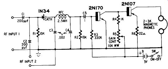
Fig. 919. Radio-frequency comparator.
... for oscillation. The ends of the windings have been given corresponding letter symbols in Figs. 920 and 921.
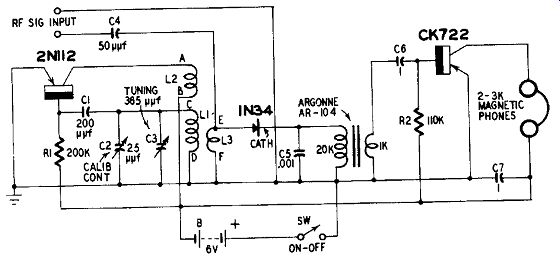
Fig. 920. Heterodyne frequency meter.
The detector (mixer) stage employs a 1N34 germanium diode.
The oscillator output is coupled into this diode through winding L3 of the coil combination. The external signal is coupled to the diode through capacitor C4 from the RF SIGNAL INPUT terminals.
The single-stage audio amplifier (Raytheon CK722) is transformer-coupled for maximum of power gain.
The initial calibration of the instrument may be made in the following manner: (1) Feed a 500- khz unmodulated signal into the instrument through the RF SIGNAL INPUT terminals. (2) Set the tuning capacitor C3 to its full-capacitance position. (3) Adjust trimmer C2 for zero beat. The C3 dial now may be marked 500 khz at this setting. (4) Substitute a 100- khz frequency standard for the signal generator. (5) Reset C2, if necessary, to establish a more accurate zero beat with the standard. (6) Tune C3 slowly from this 500-khz setting until the next standard-frequency point is tuned in at zero beat. Mark this point 600 khz on the C3 dial. (7) Repeat at each standard spot frequency, marking the dial 700, 800, 900 and 1,000 khz accordingly. If the frequency standard is equipped also with a 10-khz multivibrator, 10-khz points may be located and in scribed between adjacent 100-khz graduations on the dial.
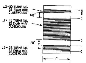
Fig. 921. Detail of coil for heterodyne frequency meter.
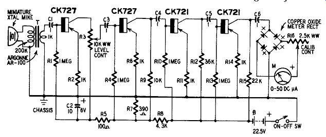
Fig. 922. Sound-level (noise) meter.
Periodically, a single-point frequency check of the heterodyne frequency meter may be made in the following manner: Set the dial to 1,000 khz (1 mhz) and, with a 100- khz frequency standard delivering a signal to the RF SIGNAL INPUT terminals, adjust trimmer C2, if required, to re-establish exact zero beat. This single adjustment compensates for any frequency drift due to variations in circuit or battery characteristics that have occurred since the initial calibration.
Sound-level (noise) meter
Fig. 922 shows the circuit of a compact portable instrument which may be used to make sound surveys and noise measurements. If a piezoelectric vibration pickup is substituted for the crystal micro phone, this instrument becomes a vibration meter. It also may be employed without change as an electronic stethoscope.
The instrument consists of a crystal microphone, four-stage high-gain af amplifier and output meter. Low-noise transistors (Raytheon CK727) are used in the two input stages; high-alpha audio units (Raytheon CK721) in the last two stages. Voltage divider R7-R8 reduces the collector supply to 2 volts for the two CK727's.
Potentiometer R3 serves as the LEVEL control. A precision step-type potentiometer (attenuator) may be used in this position when accurate decibel steps are required. Rheostat R16, the CALIBRATION CONTROL, is set for full-scale deflection of meter M with a standard sound input and with R3 set for maximum transmission.
The response of the instrument, not including the microphone, is 7 db down at 10 khz and is-14.8 db at 20 khz. Flat response is obtained from 50 to 1000 cycles, dropping to-2 db at 5,000 cycles.
AF-Rf signal tracer
The signal tracer circuit shown in Fig. 923, unlike many early transistorized tracers, is competitive with tube circuits since it has high input impedance (0.5 megohm) , adequate audio output for loudspeaker operation (100 mw) and provides aural (loudspeaker) and visual (meter) indications. Its low current drain permits operation from self-contained flashlight-type batteries, giving complete divorcement from the power line, compact construction, full port ability and freedom from interaction with the device under test or with the signal generator.
An amplitude-modulated test signal is employed when tracing rf signals with this instrument. An af signal at any frequency between 50 and 20,000 cycles is satisfactory for tracing in audio systems. The rf probe contains a 1N34 germanium diode which acts as a demodulator. The af probe is a conventional meter-type unit containing no resistors, diodes or capacitors. Both probes have shielded cables terminated with shielded phone plugs for insertion into INPUT jack J.
The tracer circuit is a four-stage, high-gain, high-output af amplifier employing five p-n-p transistors. The high input impedance of the first stage (1 megohm at the common test frequencies of 400 and 1,000 cycles) is due to the connection of the first transistor (Raytheon CK725) as an emitter follower. This basic input impedance is reduced approximately to 0.5 megohm by the shunting effect of the GAIN CONTROL potentiometer R1.
The high gain of the amplifier is contributed by the two inter mediate stages (Raytheon CK721) . The push-pull class-B output stage also employs two Raytheon CK721 p-n-p transistors.
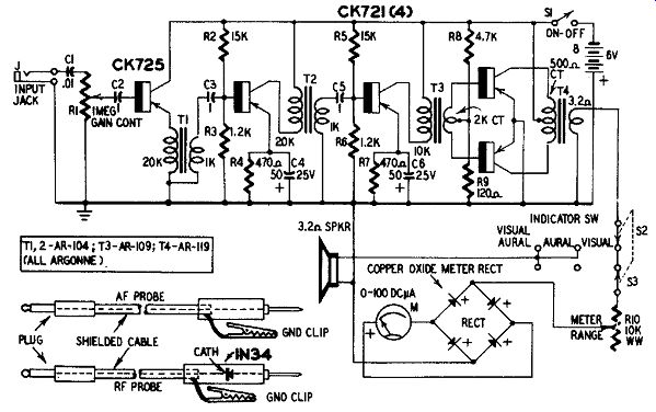
Fig. 923. Af-rf signal tracer.
The two-pole three-position indicator switch S2-S3 allows the operator to select visual or aural indication, or both. When this switch is set to its right position, the output-signal voltage is de livered only to the output meter circuit. When S2-S3 is at its center position, output is delivered only to the loudspeaker. And when S2-S3 is set to its left-hand position, output is delivered to both meter and speaker. The METER RANGE rheostat R10 allows the deflection to .be restricted to the full-scale point of the meter scale when GAIN control R1 is operated wide open.
"Grid"-clip oscillator
Fig. 924-a shows the circuit of a conventional dip oscillator which covers the tuning range of 1 to 30 mhz in four plug-in-coil bands: 1-3.5, 3.4-9, 8-20 and 18-30 mhz. The word grid actually is a misnomer in the name of this transistorized instrument since no grid is present.
The oscillator circuit is designed around an rf transistor (Philco SB100). Individual transistors of this type may oscillate as high as 45 mhz. However, all units should reach 30 mhz with no difficulty.
The indicating meter is an rf voltmeter consisting of the 1 N 34A diode, 0-100 dc microammeter M and the METER SET rheostat R1, capacitance-coupled across the tuned circuit through C3.
---------------

Table 8-Coil Table for "Grid"-Dip Oscillator
Coil A 1-3.5 mhz Coil B 3.4-9 mhz Coil C 8-20 mhz Coil D 18-30 mhz
L1: 72 turns No. 32 enameled wire closewound on 3/4-inch-diameter form.
L2: 18 turns No. 32 enameled wire closewound on same form as L1. Space 1/16 inch from low end of L1.
L1: 19 turns No. 22 enameled wire closewound on 3/4-inch-diameter form.
L2: 5 turns No. 22 enameled wire closewound on same form as L1. Space 1/16 inch from low end of L1.
L1: 9 turns No. 22 enameled wire on 3/4-inch-diameter form. Space to winding length of 1/2 inch.
L2: 4 turns No. 22 enameled wire on same form as L1. Space to winding length of 3/8 inch.
Space 1/16 inch from low end of L1.
LI: 3 turns No. 22 enameled wire on 3A-inch-
diameter form. Space to winding length of 1/2 inch.
L2: 3 turns No. 22 enameled wire on same form as 1. Space to winding length of 1/4 inch.
Space 1/16 inch from low end of L1.
------------------
A tickler-feedback oscillator circuit is employed. Each plug-in coil consists of a tuned winding (L1) and tickler winding (L2) wound on a 0.75-inch-diameter plastic plug-in form. Amphenol
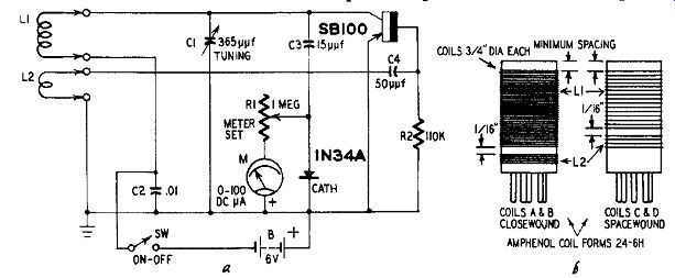
Fig. 924-a,-b. "Grid"-dip oscillator.
24-6H forms have been specified for this instrument since they are obtainable in the required diameter. However, only four of the six prongs of these forms are used for coil connections.
Fig. 924-b shows constructional details of the coils. Note that each L1 winding is placed as close as possible to the top of the form to facilitate inductive coupling into the external circuit under test.
The coil table gives winding data.
This dip oscillator is used in the regular manner. Potentiometer R1 is adjusted for full-scale deflection of the meter and must be reset as capacitor C1 is tuned through a band. A strong downward dip is obtained when resonance is established with the external circuit under test.
Low-frequency "grid"-dip oscillator
Broadcast and intermediate frequencies are covered by the single-range dip oscillator circuit shown in Fig. 925-a. This instrument has a tuning range of 350-1,700 khz without plug-in coils and in this range is convenient for the usual resonance, capacitance and inductance measurements afforded by "grid"-dip oscillators. An inexpensive rf transistor (Raytheon CK768) is used.
The tuning capacitor C1-C2 is a midget 365-gif dual variable with both sections connected in parallel to give a total capacitance of 730 uf This unit must be insulated from the chassis or case since both the rotors and stators are above ground.
Fig. 925-b shows constructional details of the L1-L2 coil assembly. The tuned coil L1 is wound on a 1-inch-diameter form (1 1/4 inches long) . An insulating sleeve of Scotch tape or insulating paper then is wound on top of this coil, and finally coil L2 is wound
L1: 113 turns No. 32 enameled wire closewound on 1inch-diameter form.
L2: 42 turns No. 26 enameled wire closewound on insulating-paper or Scotch tape sleeve on top of L1. Wind in same direction as L1.
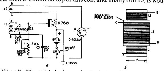
Fig. 925,-a,-b. Low-frequency "grid"-dip oscillator.
... on top of the sleeve. Both coils must be wound in the same direction. They must be connected in the circuit as shown by the letter symbols in Figs. 925-a,-b. Otherwise the feedback will not be of the correct polarity for oscillation.
"Grid"-dip adaptor
The circuit shown in Fig. 926-a permits the use of an rf test oscillator or signal generator as a "grid"-dip oscillator. The resonant frequency is read from the dial of the signal generator. Coil L in the adaptor is coupled to the external circuit under test, as when using a regular "grid"-dip oscillator, and dip is indicated by 0-1 dc milliammeter M. Rheostat R3 is the ZERO-SET control used to set the meter to zero in the absence of an input signal.
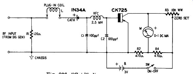
Fig. 926. "Grid"-dip adaptor.
The adaptor is connected to the rf output (modulated or un modulated) of the signal generator through the RF INPUT terminals.
The adaptor circuit may be built into a hand-type probe, with coil L inserted into its end and the rf connections made to the signal generator through a flexible, shielded cable.
The adaptor coil is untuned. All tuning is done with the signal generator. The generator output is adjusted for full-scale deflection of meter M. Three plug-in coils give the adaptor a frequency cover age of 100 khz to 250 mhz in three ranges: 100 khz-6 mhz, 5-35 mhz and 30-250 mhz. All coils are wound on 1-inch diameter plug-in forms.
Table 9 gives coil-winding data for the adaptor.

--------------------- Table 9-Coil-Winding Data for Adaptor
Coil A 86 turns No. 32 enameled wire closewound on 100 khz to 6 mhz 1-inch diameter plug-in form.
Coil B 11 turns No. 24 enameled wire closewound on 5 mhz to 35 mhz 1-inch diameter plug-in form.
Coil C 2 1/2 turns No. 24 enameled wire on 1-inch diameter plug-in form. Space to winding length of 1/8 inch.
---------------------------
The adaptor circuit consists of the untuned coil L, a 1N34A germanium diode detector, rf filter Cl-RFC-C2, high-gain dc amplifier and indicating microammeter M. High current amplification is obtained through the use of the super-alpha transistor (Raytheon CK725) . The meter-zeroing circuit is a four-arm bridge.
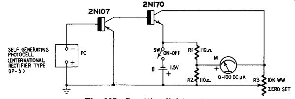
Fig. 927. Sensitive light meter.
Sensitive light meter
Most simple light meters (or exposure meters) composed of a self-generating photocell and dc microammeter have a full-scale sensitivity between 70 and 100 foot-candles. This sensitivity is in adequate for experimental low-intensity measurements.
Fig. 927 shows how a two-stage high-gain dc amplifier may be added to the simple light meter to increase its sensitivity. This circuit gives a full-scale meter deflection with 0.1-foot-candle light input.
Direct coupling is employed in the amplifier. To operate successfully from a single 1.5-volt cell B, transistors having opposite electrical characteristics are employed: one p-n-p (General Electric 2N107) in the input stage and one n-p-n (General Electric 2N170) in the output stage. The meter is connected in a bridge-type zero-set circuit. This circuit has good stability because of the drift of 40 in opposite directions in the two transistors.
In use, the meter is set to zero (by adjustment of rheostat R3) with the photocell darkened. The instrument then is ready for operation. The meter scale may be calibrated in foot-candles if a standard light source is available. The basic range 0.1 foot candle may be multiplied by means of shunt resistors connected across the photocell (2N107 input circuit) .
Instrument circuits in other sections The following instrument circuits have been described in other sections under the headings of which they most logically fall:
Audio Oscillators. Section 4.
Variable-Frequency RF Oscillator. Section 4.
Frequency Standards. (100- khz Oscillators) . Section 4.
Square-Wave Generators. (Multivibrator) .
Section 4. (Flip-Flop) . Section 7.
Modulation Monitor. Section 10.
REFERENCES
Transistorized Voltmeter, RADIO-ELECTRONICS Magazine, December, 1954; p. 54.
Electronic Compass Orients TV Antenna, RADIO-ELECTRONICS Magazine, January, 1956; p. 118.
3 Transistorized TV Antenna Compass and Field-Strength Meter, Radio 8c Television News, January, 1956; p. 43.
4 Tunable 500-to-1000- Cycle Bandpass Filter, Radio Sc Television News, August, 1956; p. 106. (Guy Dexter) . Crystal Marker for TV Alignment, Radio & Television News, July, 1956; p. 80.
Miniature Signal Injector, Audiocraft, July, 1956; p. 22.
Heterodyne Frequency Meter Uses Pair of Transistors, RADIO ELECTRONICS Magazine, October, 1953; p. 88.
8 Transistor Dip Oscillator, Radio & Television News, July, 1955;p. 51.
* Author is Rufus P. Turner.