The latest Intelsat V series of satellites promises greater capacity through the use of advanced technology. Brian Dance reports.
IF ONE PICKS UP a telephone and makes an intercontinental call, the chances are that it will be connected through one of the satellites stationed over the India, Pacific or Atlantic oceans. The demand for international telecommunications has increased enormously during the past few years and increasingly sophisticated satellites have been placed in orbit to provide more and more channels. Most of the satellites currently in use are cylindrical in shape with solar cells on the outside of the body, but future trends are stretched arms so that all of the solar cells are directed towards the sun. These new look satellites will provide even more channels of communication than their predecessors.
About 80% of satellite traffic is for telephone use. Although long distance television signals produce quite an impact in millions of homes, television accounts for only about 2% of the use of global satellite communications. About 15% of the traffic is for data and message transmission. Apart from international communications, satellites are now used for communications across a single country such as Canada, Nigeria, Indonesia, etc.
Satellites are used for conveying television signals to remote areas and it is rather interesting to note that the earth station which received more occasional television transmission in 1975 was any other earth station was at Manaus--a Brazilian rubber port about 1 400 km up the river Amazon!
HISTORY
A regular inter-continental telephone service was first introduced from London to New York in 1927 using a 60 kHz transmitter, but the first trans-Atlantic cable became available in 1956 with 48 speech circuits and provided much better quality and reliability. Reflections from the moon were used to provide a speech link across the U.S.A. in 1956, but our natural satellite is a poor reflector of radio waves and is too far away for low noise wide band signals.
The first artificial communications satellite, Echo 1, was a balloon about 30 m in diameter which was launched in 1960. Its aluminized surface reflected both radio waves and light very well; it formed a very bright object in the sky which has probably been seen by more people than any other man made object. Echo 1 orbited the earth in about two hours and acted as a passive reflector of radio waves so that it could be used to relay signals between Europe and the U.S.A. Echo 2 was rather similar, but the first television transmissions between the U.S.A. and Europe were carried by Telstar 1 in 1962; this satellite had its own transmitter operating on 4170 MHz with a power of 2.25 W. the power being provided by 3 600 solar cells. These and similar satellites had the severe disadvantage that they were visible from any earth station only for a short time--about 20 minutes in the case of Telstar 1--and had to be followed across the sky by the earth station aerials. Complex systems using as many as 50 satellites were proposed so that continuous communications could be maintained, but each earth station would have required at least two aerials so that one could follow the satellite whilst the other searched for the next satellite coming above the horizon.
A much better system was proposed as long ago as 1929 in which satellites in circular orbits 36 000 km above the earth are used; such satellites have orbital periods of about 24 hours, so they can be made to appear stationary from a point on the earth. The early rockets did not have enough power to place a satellite in one of these geosynchronous orbits. In addition, it took time to develop the technology required to enable the satellites to be maneuvered in orbit, etc. Satcom 1 was the first geosynchronous satellite launched in 1963, but all modern communications satellites are geosynchronous.
The International Telecommunications Satellite Organization (INTELSAT) was founded in Washington in 1964 to provide telephone and television communications to all users on a non-discriminatory commercial basis. INTELSAT owns the satellites and leases circuits to numerous countries, but the earth stations are normally owned by the telecommunications authorities in the countries concerned.
The INTELSAT satellites launched up to the present time are known as the I, II, Ill, IV and IVA series, whilst a new type V series is planned for this year. The first INTELSAT I ("Early Bird') could carry only 240 telephone conversations and could communicate with only two earth stations at any time. INTELSAT II ("Blue Bird') had the same capacity, but could operate with several ground stations simultaneously.
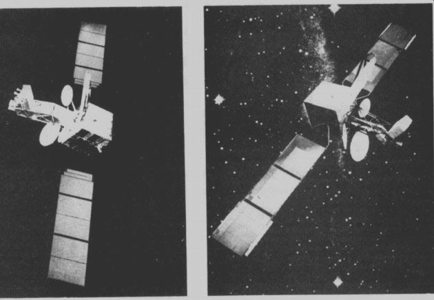
Figs 1 and 2. These two models show the outstretched solar arrays of
the Intelsat V satellite.
The INTELSAT III, IV and IVA vehicles have bodies which are spinning for optimum stability, the rate of spin being of the order of 1 revolution per second. The aerials are placed on a 'de-spun' shelf so that they point in a constant direction. Special lubricants are required for the bearings in the high vacuum of space which can operate over a wide temperature range. Failures occurred in over half of the INTELSAT III spacecraft, but a much greater proportion of the INTELSAT IV and IVA craft have provided the desired performance.
The aerials of the INTELSAT IV satellites include 'global' beams for covering the largest possible area of the earth (including remote islands) and spot beam antennae which provide a 4.5 beam for optimum communication with areas where the traffic density is very high. Each successive type of satellite provides more channels of communication. The main improvement in the IVA-series is the use of directional aerials for the east and west beams so that the same frequencies can be used in both of these beams without mutual interference.
INTELSAT V
One of the main disadvantages of the cylindrical spin stabilized craft is that only a small proportion of the solar cells on the cylindrical body are facing the sun at any one time. Thus the available power is much smaller than that which could be obtained from a satellite with a similar number of cells which all face the sun. The new INTEL SAT V vehicles will therefore employ three axis body stabilization with the solar cells on extendible arms 'which can be rotated so that all of the cells face the sun at all times. This type of system can provide about three times the power per square meter of solar cells than in a spinning satellite. The new satellites will use the 11 GHz and 14 GHz bands for communications as well as the 4 GHz and 6 GHz bands used by the existing INTELSAT craft.
The contract for the supply of INTELSAT V vehicles was awarded to Aeronutronic Ford (now Ford Aerospace and Communications Corporation) in September 1976 at a cost of $236 million for seven satellites with options on a further eight. Each INSTELSAT V craft will have a capacity of about 12 000 telephone channels and 2 color television channels. The first will be placed over the Atlantic to cater for the very heavy traffic in that region. The second will be a spare for the first, whilst the third is scheduled for the Indian Ocean (including Australian use). It is hoped to use the NASA space shuttles to launch some of these craft, since this should reduce the cost from about $ 25 million to $15 million.
All seven craft are due for launching by May 1981.
The INTELSAT V Atlantic satellites will employ space diversity with shaped beams to the east and west so that Europe and Africa are covered by the east beam and North and South America by the west beam. Thus the 500 MHz wide frequency band will be used twice, as in the current IVA craft. In addition, INTELSAT V will re-use the frequency spectrum a second time for the Northern Hemisphere where the traffic demand is heavy. This will be accomplished by polarizing these additional beams perpendicularly to the normal beams. The simultaneous use of polarization and directional isolation is one of the major technical challenges of INTELSAT V.
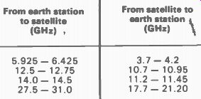
TABLE 1 Frequencies used for satellite communications.
FREQUENCIES
The current INTELSAT system employs frequencies in the 6 GHz band for transmission from the earth stations, whilst the satellites transmit in the 4 GHz band. These frequencies and other likely to be used are shown in Table 1.
The bandwidth at the lower frequencies is 500 MHz, but, there is a 3.5 GHz bandwidth in the 19 and 29 GHz bands for the up and down links respectively. In general the use of the bands is shared with terrestrial services and there is a limit to the power which can be used to avoid interference. However, the frequencies of 19.7 21.2 GHz and 29.5-31.0 GHz are to be reserved exclusively for down and up satellite links respectively.
The maximum permitted power in the 4 GHz band is--152 dB W / m2/4 kHz at arrival angles of less than 5' rising to -142 dB W / m^2/ 4 kHz at arrival angles of 25' or more. These values are 2 dB higher in the 11 GHz band, whilst in the shared part of the 20 GHz band it is increased by a further 11 dB, but the latter is specified for a 1 MHz rather than a 4 kHz bandwidth.
The greater available bandwidth and reduced chances of interference makes the use of the higher frequency bands very attractive, but one of the most fundamental obstacles to the use of frequencies above 10 GHz for satellite communications is the degradation of the signal by heavy rain in the vicinity of the receiving station. Rain and precipitation in the atmosphere not only attenuate the signal from a satellite, but cause de-polarization, increased noise and increased interference between terrestrial and satellite systems. Even when 4 GHz signals were being received from the early Telstar satellite, it was noted that the noise level increased when the receiving station was near heavy rain.
The effects of rain can be overcome by the use of diversity techniques with switching between two or more receiving stations, but this is obviously expensive.
The use of high transmitter power also helps to reduce the effects of rain.
Telemetry and command signals are transmitted to the satellites within the communications band, but outside the communications channels themselves. The INTELSAT IV spacecraft have 223 command channels.
POSITIONAL CONTROL
Gravitational fields due to the sun, moon, etc. and variations in the earth's gravitational field cause small movements in the position of a geosynchronous satellite. Solar radiation pressure also produces a small effect which accumulates with time. The drift in the orbit inclination out of the equatorial plane is about 0.8- per year in the case of small inclinations. If uncorrected, the would cause the satellite to move progressively around in a figure of eight. In addition, a satellite is accelerated towards two stable points at 75'E and 105' W due to the non-uniformity of the earth's gravitational field.
When a satellite has moved from its desired position by a certain amount, small thruster jets operated by command signals from the earth cause it to return to the desired position. The gas jets used consist of a mixture of nitrogen and hydrogen obtained by admitting liquid hydrazine into a reaction chamber containing a catalyst which causes the liquid to separate into its two constituent elements. Jets can also be used to keep the aerials on the de-spun shelf of existing satellites pointing towards the earth with an accuracy of 0.1 0; the reference direction may be obtained by an infra-red sensor detecting radiation from the earth and from the sun.
Although the use of geosynchronous satellites gives Vise to the problems discussed, it brings many advantages, such as no Doppler shift of the signal frequency, few thermal stress cycles, low radiation environment, low magnetic fields, etc. The earth subtends an angle of about 18 at a geosynchronous satellite; a global beam from the satellite will cover about 4/ 10 of the earth's surface, so ground stations can be linked over great circle distances of up to 17 000 km.
POWER LEVELS
The variation of the signal power level at various points is extremely large. Let us trace the levels which are typical for a television signal being relayed from one amplifier in an earth transmitting station to the output of the amplifier of an earth receiving station.
The signal comes into the transmitter power amplifier at a level of around 1 mW, but is amplified to a level of a few hundred watts before it is fed to the aerial at the centre of one of the giant 30 meter diameter dish aerials.
This dish provides an effective gain of about a million by concentrating the power into a narrow beam; a power of a few hundred megawatts would be required to achieve the same signal level at the satellite if this power were radiated equally in all directions. This signal is attenuated by a factor of about 1 020 during its journey to the satellite, so it arrives at a level of a few picowatts. The satellite aerial provides a gain approaching one hundred and the satellite receiver amplifier a gain of about 100 000, so the signal leaves the receiver at a level of about 100W. Power levels in the circuits from the satellite back to earth are of the order of one million times lower than those in the up path in many cases. The 10 uW signal from the satellite receiver is amplified to a level of about 10 W and fed to an aerial with a directional gain of about 50; the effective power radiated by the satellite is thus around 500 W. This suffers a loss of the order of 10^20 in the down-path, so it arrives at the ground station receiving aerial at a level of about 5 attowatts (1 attowatt = 10^-18W). However, the enormous receiving dish provides a gain of about a million to bring the signal level up to around 5 pW; without such a dish, the signal would be lost in noise. The signal is then amplified in the ground station receiver system so that its power level is brought up to about the lm W level (similar to the level at which it arrived at the power amplifier of the ground station transmitter at the start of the cycle). It is difficult to fully appreciate the enormous range of power levels involved. This range is some 10^26 times or 260dB between the effective power radiated from the transmitting aerial of the earth station and the effective power level at the aerial of the receiving earth station.
SATELLITE REPEATERS
A satellite repeater accepts the incoming signal, amplifies it, changes its frequency for the new band and amplifies the power level for re-transmission. Frequency modulation is normally employed for simplicity in both the up and down links, the modulation being identical in each case. In the Intelsat IV craft, the band is divided by a filter into 12 channels of 36 MHz each with a 40 MHz spacing of the centre frequencies.
The incoming signal in the 5.932 to 6.418 GHz region is fed to a tunnel diode amplifier operating at the signal frequency. It is then converted into a 2225 MHz signal for broadband amplification before being converted into a 4 GHz signal which is passed to a travelling wave tube for power amplification. These tubes offer efficiencies of about 30% and require a high voltage supply. There is a four fold redundancy in the electronic systems of a satellite to ensure reliability is high.
Tunnel diode amplifiers are simple and light in weight, but other amplifiers can be used in the receiver circuits of satellites. For example, the European Orbital Test Satellite (OTS) uses a parametric amplifier operating in the 11 and 14 GHz bands instead of a tunnel diode. It seems likely that gallium arsenide (GaAs) field effect transistors will replace tunnel diodes and possibly even travelling wave tubes at frequencies of up to at least 14 GHz.
EARTH STATIONS
The design of earth station equipment is very different from that of the circuits in the satellite, since the weight and size of the ground station aerial can be far greater than that of the satellite system. In addition, ample power is readily available at earth stations. The carrier power required from a satellite is approximately inversely proportional to the gain of the earth station aerial in the receiving direction (G,) and directly proportional to the earth station noise temperature (Ts). Thus the factor G,/T, can be used as the figure of merit for an earth station which is conveniently expressed as 10 log,c , (G,/ Ts ) dB r K. This figure of merit is an important parameter of an earth station, since it determines the traffic handling capability. The figure of merit is usually measured by pointing the aerial at a distant radio star so that the noise level may be compared with that of other aerials using the same star. This method is most satisfactory for large aerials, but the moon may be used for smaller 10 meter diameter dishes. For small aerials of up to 8 m diameter, it is more convenient to obtain the figure of merit from the noise temperature and gain.
All standard earth stations in the INTELSAT network must have a high figure of merit, namely 40.7 dB / K. An aerial of at least 26 m diameter is required to obtain this figure, but a 30 m dish is normally used to give more flexibility in the positioning of low noise receivers by using longer wave guides with higher losses. The total weight of a '5th generation' standard aerial for INTEL SAT use is about 300 000kg and the overall height some 28m.
The satellites are not quite stationary. A fixed antenna is unsatisfactory, since the aerial beam angle is narrow (about 0.2c at 6 GHz for a 30 m aerial). A servo system is usually used to control the movement of the aerial, the error signal being obtained by using a beacon signal emitted by the satellite. Most aerials are fully steerable and can be moved to operate with any satellite.
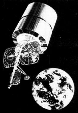
Fig 3. The antennas of the Intelsat Ill and IV satellites are "de-spun" on
a shelf.
EARTH STATION RECEIVERS
Some of the very early earth station receivers employed master amplifiers in the first stage, but these amplifiers cannot operate over the wide bandwidth used in the INTELSAT system. A very low noise amplifier is essential to handle a low power signal over a 500 MHz band width.
Parametric amplifiers cooled to about 15 K are usually employed. Such an amplifier can provide a gain of some 30dB with an effective noise temperature of about 15°K. It may be followed with a tunnel diode amplifier giving a gain of about 10 dB or with a travelling wave tube amplifier. Continuously operating cryogenic cooling devices using gaseous helium have been developed in which the helium is re-circulated in a closed system.
Although the receiver noise temperature is about 15 K by losses in the feeders, by 15 K by side lobe pick-up and by 25' K by atmospheric absorption. Thus the total effective noise temperature is about 70'K. Each earth station receives a carrier from every other earth station with which it wishes to communicate. The number of carriers sent from stations is reduced to a minimum by using a single carrier for conveying signals to various destinations. Thus the number of transmitted carriers is lower than the number of signals received by various stations.
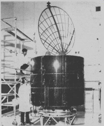
Fig 4. Intelsat satellites are not small, as can be seen here. The use
of the Space Shuttle will reduce launch costs tremendously.
EARTH STATION TRANSMITTERS
The power required from an earth station transmitter depends on the aerial gain, on the geographical position and on the gain of the satellite system. The latter will depend on whether global or spot antennae are being employed and on the number of channels available. The required power can be obtained at the earth station by using narrow band transmitters (some tens of MHz) using klystrons or a wide band transmitter using travelling wave tubes (500 MHz bandwidth). If klystrons are used, each carrier is amplified to a suitable level in a separate transmitter and the outputs of the transmitters are combined before the signals are fed to the aerial.
This arrangement is used mainly in stations operating with relatively few carriers. The initial cost and the running costs are fairly small with klystrons, but long breaks are required to change frequencies.
Large stations operating with many carriers favor travelling wave tubes. The carriers are combined at low power and then are amplified by the wide band transmitter before being passed to the aerial. The non linearity of the travelling wave tube produces some intermodulation products at the output and these must be limited by operating the tube some 10 dB below its capability to prevent interference with other signals.
Travelling wave tubes are more expensive and less efficient than klystrons in these circuits, but their wide band capability is very convenient.
DOMESTIC SATELLITES
THERE is a rapidly growing demand for communications via 'domestic' satellites across a single country. Signals from satellites used for this purpose can be concentrated within the boundaries of a nation so smaller earth station aerials can be employed than for international communications where the beam energy must be more widely dispersed. For example, 10 m diameter antennae give Gr / T s values of around 31 dB / ° K, whilst 10 m antennae of Gr /T2 about 26dB / ° K are being delivered in the USA for receiving only television signals. Antennas of 2 to 3 m in diameter with a figure of merit of 14 to 20 dB /°K can be used in remote areas for providing 12 voice channels for emergency use or on oil drilling rigs, etc.
Telephone companies cannot charge such high rates for inland calls as they do for international calls, so the viability of domestic satellites is more severely limited by costs than that of international communications systems. However, domestic systems are now well established in countries such as Canada whose Telesat system provides television and voice communication throughout the country, the USSR (mainly television), the USA, which has three systems provided by three different companies and various other countries.
Some countries, such as Spain and Mexico, have leased INTELSAT circuits for their domestic use, but the charges are high enough to make it more economical for most large countries to have their own system. In some cases a group of countries close together can jointly own a system.
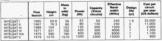
TABLE II. The INTELSAT satellites
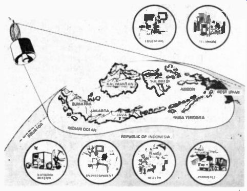
Fig 5. Satellite Communication is ideal for areas such as Indonesia.
COMPARISON WITH CABLES
Satellite communication links are generally cheaper than long distance cables operating under the ocean, but the cables have a minimum expected life of 25 years against 7 for a satellite. It is uneconomic to connect remote islands by cable, so satellite or radio links are used.
Satellites are essential for carrying high bandwidth signals (like television) over intercontinental distances.
The new TAT-6 cable laid across the Atlantic can carry 4 000 voice channels, but satellites of the IVA series can carry 6 000 speech channels and some domestic satellites even more. Cables may be more vulnerable to enemy attack and communications are vital in war.
A peculiarity of a satellite link arises from the fact that the signal must travel rather over 36 000 km to the satellite and a similar distance back to the earth. Thus there is a delay of about a quarter of a second before the signal reaches its destination and a delay of at least half a second before any response reaches the sender. If a signal received by a satellite was transmitted to another satellite before being returned to earth, the delay of a second or so before any response could be returned to a person might be unacceptable in ordinary telephone conversations. The longest delay on sub-oceanic cables is about 1/16 second.
CONCLUSIONS
Satellite communications are one of the most useful products of the huge investment in space technology.
They have radically changed the pattern of world communications and confer outstanding benefits on the lives of ordinary people. It seems likely that satellites able to handle 100 000 telephone circuits will be developed without any great increase in the satellite mass. Improvements in frequency re-use, 3 axis body stabilization, high efficiency solar cells, on board switching, hybrid modulators, etc. will provide great improvements. The life of satellites is partly limited by the life of the batteries used to provide power when the vehicle is eclipsed by the earth, but new nickel-hydrogen cells are showing great promise for this application.
(adapted from: Hobby Electronics magazine, Mar. 1979)
Also see: