by Owen Bishop
It's fast, accurate and not too fancy. The HE Digital Capacitance Meter is easy to build and will become one of the most used items in your workshop.
A GLANCE through an electronics catalogue soon shows that most of the cheaper multimeters do not measure capacitance. A few may measure values in the microfarad range, but not many measure in the nanofarad or picofarad ranges. This low-cost meter will, therefore, be very useful; it covers values from 100pF to 9900uF with two digit accuracy, it's cheap and easy to build. It also provides a good indication for values in the 10-100pF range but, in general, the main ranges will satisfy the requirements of most hobbyists.
Many types of capacitor are manufactured to about 10% tolerance yet, for building filters, tuned circuits, timers and the like, it is often important to be able to know the precise value of a capacitor. Electrolytic capacitors, for example, are notorious for having very wide tolerance and for changing capacitance with age and use. Then there are all those look-alike polystyrene capacitors, which are marked in ink that seems specially prone to rub off at the first handling (their physical size is no real guide to their value, by the way). Finally, there are the bargain packs, containing an assortment of imported capacitors whose markings bear no recognizable relationship to any known classification system. When using these, the perplexing question is: "What have we here?". So, a capacitance meter is a distinct asset for these and many other circumstances.
------------
How It Works
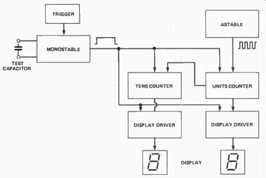
The HE DCM measures an unknown capacitor by counting the number of clock pulses which occur during the period of a gating pulse, produced by the monostable. The pulse is triggered by operating a push button switch (the trigger circuit ensures a clean start to the pulse) and its width is proportional to the value of the test capacitor, which is connected into the RC timing network of the monostable.
The gate pulse 'enables' the display drivers and the counters, which then begin to register pulses from the astable multivibrator. At the end of the monostable gate pulse, the display drivers are locked and a two digit number is displayed. The counters are reset to zero, ready to begin a new count.
The DCM has eight ranges, produced by changing the frequency of the astable multivibrator and by controlling the width of the monostable pulse by using different resistors in combination with the test capacitor. This is described more fully in the text.
-------------
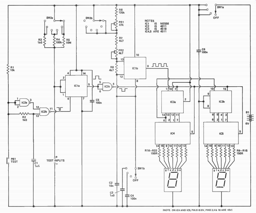
Figure 1. The circuit of the Digital Capacitance Meter.
The Circuit
The circuit uses the 556 dual timer IC in two common configurations. One half, IC1b is an astable multivibrator used to produce a square wave at either of two fixed frequencies. The pulses from the astable are counted by IC3, which contains two complete decimal counters. The first counts units and its output carries over to the second, which counts tens. The display drivers, IC4 and IC5, convert the BCD (Binary Coded Decimal) outputs from the counters to provide the outputs required for driving the 7-segment displays.
The counting action is controlled by the other half of the timer, IC1a, connected as a monostable multivibrator; when triggered, this gives a single positive pulse. As the pulse begins (rises), the counters and display drivers are 'enabled' and pulses from the astable are counted. As the pulse ends (falls), the display drivers are latched to 'hold' and the count is displayed. 1 he counters are reset to zero at this time, ready to restart the count at the next high pulse, but the display 'holds' the count. The display is returned to zero by the enable pulse at the beginning of each run and counting begins immediately.
The length of the pulse from the monostable, IC1a, is proportional to the capacitance of the test capacitor; the greater the capacitance, the longer the pulse and, therefore, more pulses from the astable are counted. The two figure display is read according to the format indicated by the range-setting knob.
The period of the monostable is set by the test capacitor and whichever resistor, R3, R4 or R5, is selected by SW2a. The frequency of the astable, IC1b, is set by the timing capacitors C2, C3 or C4 and resistors R6, PR1, R7 and PR2. By selecting the appropriate combination of timing components, the meter provides eight decade ranges from 100pF upwards.
Construction Most of the circuit is accommodated on the printed circuit board. It is best to begin construction with the display circuit. The two 7-segment LED displays are soldered to the board first; make sure the iron is hot and work quickly, so as not to overheat the LEDs. It is better to solder a few pins, then wait a few minutes for the heat to escape before continuing; the decimal point pins (dp) do not need to be soldered. Next, mount R9-22 (or you could use two 14-pin DIL resistor arrays, if you wish).
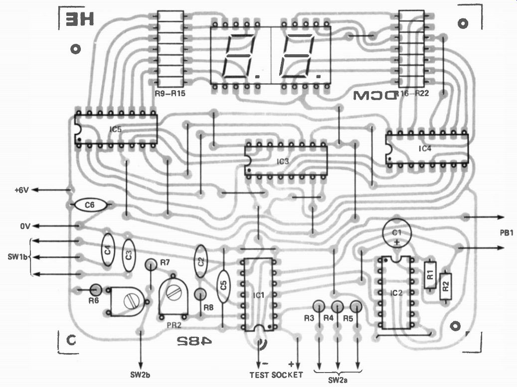
Figure 2. The component layout; note that R9-15 and R16-22 can be either
individual resistors (as shown) or 14-pin DIL resistor arrays.
When you have mounted the displays and resistors, make the battery connections and test the display. Temporarily join the positive line to each of the resistors in turn and check that the correct segments light up on the display. WARNING --the current must go through a resistor before it goes to a segment.
The two segment-drivers, IC4 and IC5, are wired in next. The counter, IC3, completes the display section of the meter. To check its operation, connect a pulse generator to pin 1 of IC3; the displays should show a regular count up to 99, returning to 00 and repeating. If you do not have a generator, you can use the output from IC1b which, with its associated components, is the next section of the circuit to be completed.
When the pulse generator (or astable) circuit is complete, connect the power supply. When pin 4 of IC2c is taken low (to 0 V), the display should count rapidly at about 1 kHz. When it is taken high, the count freezes at its current value. The rate of counting is too fast to see properly (the display will appear to show a steady '8'), but you can slow it down by temporarily wiring a large value capacitor (say, 10uF) in parallel with C2. This will let you check that the counters are working properly.
Finally, complete the monostable and trigger circuits, IC1 and IC2, and the remaining components. You will need to make off-board connections to SW2, PB1 and the capacitor test sockets before this part can be tested.
It is probably best to mount the panel components and complete all the off board wiring now. Determine the orientation of SW1 and SW2 and drill the registration holes accordingly. If PB1 and the negative capacitor test socket are correctly positioned, the tag of the socket can be soldered directly to one of the lugs of PB1. The power comes from four HP7 (or similar) cells in a battery holder, which can be held in placed by a 'sticky fixer'. To test the complete circuit, mount a capacitor in the test sockets; it is useful to have a pair of test leads, with 4 mm plugs at one end and crocodile clips at the other, for short-lead and otherwise 'difficult' capacitors. Remember to observe polarity, when testing electrolytic or tantalum capacitors.
You are now ready to switch on and . . . the display should immediately show a value. If nothing happens when you switch on, check that the trigger circuit, which normally has a high output (IC2b, pin 11), goes low for an instant (about 1 mS) when PB1 is pressed. The output of IC1a (pin 5) should normally be low, going high for an instant when PB1 is pressed. If you use a 100 uF test capacitor with SW2 at X1 n, the output should stay high for about 10 seconds and, during this time, the display will run from 00 to 99 several times.
Calibration IC1a is a monostable oscillator that controls the period for which the display counts pulses from IC1b. The period, t, is equal to 1.1RC, where C is the value of the test capacitor and R is the value of whichever resistor (R3 to R5) is switched into circuit. For example, if the test capacitor is 10 nF and we use R4 (100k), t = 1.1 x 100 x 10^3 x 10 x 10^-9 = 1.1 mS. During this brief period the counter has to count 10 pulses from IC1 b so that the display shows '10' at the end of the counting period. Now 10 pulses in 1.1 mS is equivalent to a frequency of 9.09 kHz, and this is the frequency to which IC1b is set when PR1 and R6 are short-circuited out of the timing chain by SW2b. If the test capacitor is 100 nF, the period becomes 11 mS; the display must again count 10 pulses, to show '10', so the frequency of IC2 must be reduced to 0.909 kHz by switching PRI and R6 into circuit.
To calibrate the instrument we simply have to adjust PRI and PR2 to give frequencies of 9.09 kHz and 0.909 kHz. The easiest method is to use an oscilloscope. Switch SW2 to position 1, bypassing PRI and R6; monitor the output from pin 9 of IC1b and adjust PR2 until the period of the signal is 1.1 mS (9.09 kHz). Now switch SW2 to position 2 and adjust PR1 until the period is 11 mS (0.909 kHz) --do not re-adjust PR2 at this stage.
The astable is not calibrated for the two slow frequencies, which are used with test capacitors over 100 uF in value. Additional timing capacitors, C3 and C4, are simply added to the timing chain by switching them in via SW1.
With C4 in circuit and SW2 in position 6, the frequency becomes 90.9 Hz; with C3 in, it becomes 9.09 Hz.
The accuracy of these two ranges depends on the tolerance of C3 and C4. The polyester capacitors recommended have a tolerance of 10%, which is close enough for this end of the range. You could, of course, purchase several of the same nominal value and test them (using this meter!) to find two closest to the specified values.
If you have no oscilloscope, the only method of calibration is to put a close tolerance capacitor in the test socket and adjust the astable circuit until the correct reading is obtained. It is better not to do this on the lowest range, for stray capacitance may bias the results.
Use a 47 nF polyester capacitor on the X1 nF range and adjust PR2 to get a reading of '47' almost every time (you may occasionally get '46' or '48', but errors should be no greater than this). Then use a 4n7 polystyrene capacitor on the X100 pF range and adjust PR1 until '47' is obtained. The meter should then be correct for all the other ranges.
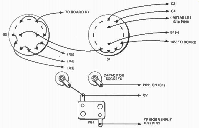
Figure 3. Wiring diagram for the panel-mounted components. Check against
the circuit to ensure all the wires go to the right place!
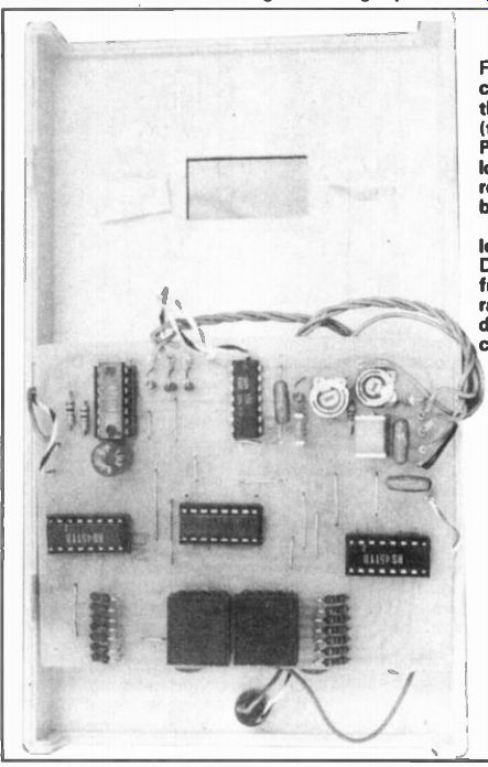
Figure 4. Internal view of the completed DCM, showing the insulated bezel
fixings (the display window) and the PCB connecting pin locations. Note
that the three resistors at the bottom of the board are mounted vertically.
In our prototype, we used long-legged wire-wrapping DIL socket pins (available from Vero Electronics) to raise the seven-segment displays so that they were 3 closer to the bottom surface r of the window, producing a brighter display. It's a trick worth trying.
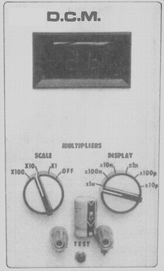
Using the Meter
Plug the test capacitor into the socket and select the required range. If in doubt, select a range greater than the one you expect the capacitor to lie in.
Switch on, and press PB1. The value will be displayed instantly (though it actually takes a few milliseconds to get there). On all ranges, the displayed figure is multiplied by the display range and the scale factor. For example, if the display switch, SW2, is set to x1 u, the scale switch to X10 and the display reads '26', the value of the capacitor is 26 x 10 x 1u = 260 uF. If the tens digit is zero, switch to the next lower range and press PB1 again.
For the two highest ranges; SW2 must be in position 6 (x1u) and SW1 turned to X10 or X100, as necessary.
Switch the meter off when it is not in use, since the display consumes considerable power. In use, however, the meter works so quickly that the reading can be taken in a couple of seconds and the battery will last for many months.
-------------
Parts List
RESISTORS
All ¼ W, 5% except where specified
R1 10k
R2 1k0
R3 1k0, 2%
R4 100k, 2%
R5 10M, 10%
R6 R7,8
R9-22 120k 4k7 150R (or two 14-pin DIL thick film resistor networks)
POTENTIOMETERS
PR1, 2
47k sub-miniature vertical presets
CAPACITORS
C1 1u0 35 V tantalum
C2 10n polyester
C3 1u0 polycarbonate
C4-6 100n polyester
SEMICONDUCTORS
IC1 556 dual timer
IC2 4011B quadruple 2-input NAND
IC3 4518B dual decade counter
IC4,5 4511 7-segment decoder/ drivers
MISCELLANEOUS
PB1 push button switch SW1,2 2-pole 6-way rotary switches PCB, two 7-segment LED displays (common cathode 0.5" ); ABS case 190 mm x 110 mm x 60 mm; knobs for SW1,2; 2 x 14-pin, 3 x 16-pin DIL sockets; 4 mm terminal sockets (1 red, 1 blue); battery holder for 4 x HP7; 1.0 mm terminal pins; self adhesive feet; connecting wire; solder, etc.
For sources of components for the HE DCM, see Buylines, page 21 A full-sized PCB foil pattern is reproduced here.
-----------------
(adapted from: Hobby Electronics magazine, Apr. 1982)
Also see: