| PREV: | NEXT: |
AMAZON multi-meters discounts AMAZON oscilloscope discounts
ill. 1 (below) shows a typical logic circuit that indicates the condition of doors on a heating oven for a painting process. The oven has two doors that both must be closed during the heating process. A fan must also be running before the electric heating coils can be energized. A limit switch is mounted near each door to indicate if the door is open or closed. A flow switch is mounted near the fan to indicate if the fan is moving air. If both doors are closed, and the start switch is turned on, the coil of control relay CR1 will become energized. When the NO contacts of CR1 close, the fan motor will be energized, causing the fan to move enough air to close the switch. When the flow switch closes, the electric heating element will begin to draw current and heat the oven. AMAZON multi-meters discounts AMAZON oscilloscope discounts |
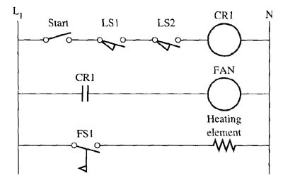
Above: ill. 1: Relay logic circuit of a heating oven for a painting process. Notice that the limit switch for both doors must be closed to energize the fan, which must be running to energize the heating coil.
| Top of Page | PREV: | NEXT: |