| PREV: | NEXT: USING RELAY LOGIC TO DETERMINE ROBOT PROGRAM FOR INSERTING STUDS INTO TAILLIGHTS FOR AUTOMOBILES |
AMAZON multi-meters discounts AMAZON oscilloscope discounts
AMAZON multi-meters discounts AMAZON oscilloscope discounts Relay logic can be used to control the extension and retraction of a pneumatic (air) cylinder, as discussed in the previous paragraph. ill. 1 (below) shows a drill press that uses an air cylinder to move a drill up and down through its drilling cycle. The cycle begins with the drill at the top of its stroke. The air cylinder is retracted and the drill motor is turned off. When the start button is depressed momentarily, the extend solenoid is energized and the retract solenoid is de-energized so that air is moved to the air cylinder to make it extend, which causes the drill to move down. The drill motor is turned on by the drill motor starter during the down stroke. When the drill is extended to its full down stroke, it will strike a limit switch that will open and cause the retract solenoid to be energized, and the cylinder retracts moving the drill back to the up position. |
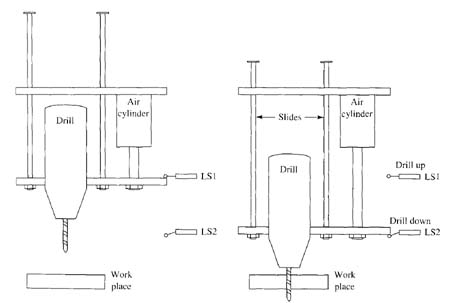
Above: ill. 1: Diagram of air cylinder used to move a drill up and down through its drilling cycle.
ill. 2 (below) shows the relay diagram with a timing diagram for the drill press. From the first line of the diagram notice that CR1 will be energized when the start button is momentarily depressed. The NO CR1 contacts connected in parallel with the start button will close when the coil is energized and seal in the start button. A second set of NO CR1 contacts is also used in line 2 of the diagram to energize the CR2 coil if the drill press is at the top position, which closes LS1.
It's important to understand that the limit switch symbol that's used for LS1 indicates this limit switch is normally open, held closed, and the symbol for LS2 is a normally closed limit switch. That is, any time the drill press is in the up position, LS1 will be held closed, and LS2 will be normally closed. When the drill press is in the down position, LS1 will move to the open position because it's no longer being held closed, and LS2 will become open since the drill is pressing against its arm, which forces its contacts open.
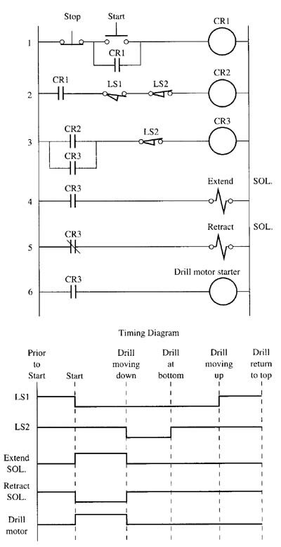
Above: ill. 2: Example of relay logic that's used to control the extension and retraction of an air cylinder to move a drill through its stroke.
From the timing diagram notice that before the start button is depressed, the retract solenoid is energized, which keeps the drill press in the up position. When the start button is depressed, the extend solenoid will become energized because both LS1 and LS2 are closed. After the extend solenoid is energized and the drill begins moving down, LSI will open, which de-energizes CR2. Since CR3 in line 3 was energized by LS1 when the press cycle was started, it must use a set of its own NO contacts to seal in LS1, so that the coil of CR3 will continue to be energized after LSI opens. The NO contacts of CR3 will keep the extend solenoid energized until the drill moves to the bottom of its stroke and depresses LS2 and causes it to open. When LS2 opens, the coil of CR3 is dc-energized, which de energizes the extend solenoid. The NO CR3 contacts in line 5 will energize the retract solenoid and cause the cylinder to retract the drill press to the up position. Since the drill motor starter coil is energized by CR3 contacts, it will also be de energized when the cylinder is being retracted. Since the drill depends on the air cylinder to provide speed for the drill, the air pressure on the cylinder must be adjusted to meet the cutting rate of the drill bit.
| Top of Page | PREV: | NEXT: USING RELAY LOGIC TO DETERMINE ROBOT PROGRAM FOR INSERTING STUDS INTO TAILLIGHTS FOR AUTOMOBILES |