| PREV: USING RELAY LOGIC TO DETERMINE ROBOT PROGRAM FOR INSERTING STUDS INTO TAILLIGHTS FOR AUTOMOBILES | NEXT: SOLID-STATE DEVICES USED FOR LOGIC |
AMAZON multi-meters discounts AMAZON oscilloscope discounts
In ill. 1 (below) notice the operation of the relay logic. Each of the three proximity switches is connected to a relay coil. Each line of the logic has a set of contacts from each of the relays connected in series. The output of each of the four lines of logic is connected to the robot as a program request. A combination of NO or NC contacts are used to ensure that the correct output is energized to tell the robot which program to run. AMAZON multi-meters discounts AMAZON oscilloscope discounts |
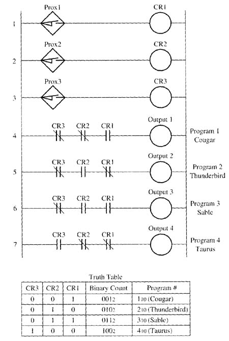
Above: ill. 1: Example of the relay logic used to determine the correct taillight assembly. The output of the logic tells the robot which one of four pro grams it should execute.
When the Cougar taillight is placed on the carrier, the finger to activate proximity switch 1 is lowered, and fingers 2 and 3 remain up. When this carrier passes the proximity switches, proximity switch 1 is activated and the coil to CR1 that's connected to it's energized. All of the CR1 contacts in the logic part of the program are activated, and all of the contacts from CR2 and CR3 remain in their normal position. Since the normally open CR1 contacts become closed when proximity switch I energizes CR1 coil, the first line of logic will become true and the robot will receive the output requesting it to run the program to insert studs into a Cougar taillight.
Lines 5 and 7 of the logic program will be de-energized because they contain NC contacts from CR1, which will move to their open position. Line 6 of the logic will also be de-energized because it has an NO set of contacts from CR2. Since the finger to activate the second proximity switch is not lowered for the Cougar taillight, the NO contact won't be closed and the output in line 6 will remain de-energized.
When a Thunderbird taillight is placed on the carrier, the technician lowers the second finger on the carrier to trip proximity switch 2, and the first and third fingers remain in the up position. When the carrier passes over the proximity switches, proximity switch 2 is activated and it energizes CR2. Notice from the four lines of logic, only the second line of logic will become true, and its output will request the robot to execute the Thunderbird program.
The fingers for the first and second proximity switches are lowered when a Sable taillight is loaded on the carrier. When the carrier passes over these proximity switches, the coils of CR1 and CR2 will be energized, which close their contacts and energize line 6 to request the Sable robot program. When the output for line 6 of the logic is energized, it sends a signal to the robot to request the program for the Sable. Since CR2 coil is energized, it will open the CR2 contacts in line 4 and line 7, causing these outputs to be de-energized. The energized CR1 coil will cause the NC CR1 contacts in the fourth line to open and de-energize output 4.
When the Taurus taillight is placed on the carrier, the third finger is lowered, and fingers 1 and 2 remain up. When the carrier passes over the proximity switches, finger 3 activates CR3. Line 7 of the logic will become activated because it has NO CR3 contacts and NC CR1 and CR2 contacts. Lines 4, 5, and 6 of the logic will be de-energized because they have sets of NO CR1 or CR2 contacts. When output 4 becomes energized, the robot is requested to run the program for the Taurus.
If you look at the output signals in the logic program closely, you will notice that they are activated when the contacts of the control relays provide the correct code. The code in this case is a binary code. If you assign CR1 the one’s position, CR2 the two’s position, and CR3 the four’s position, you would notice that the proximity switches for the Cougar provide the code 001, which equals program 1. The proximity switches for the Thunderbird would provide the code 010, which equals program 2; the switches for the Sable provide code 011, which equals program 3; and the switches for the Taurus provide code 100, which equals program 4. You could get up to eight different combinations (0-7) with the same three proximity switches. The equivalent solid-state logic circuit using logic gates for this application is shown later in this section.
| Top of Page | PREV: USING RELAY LOGIC TO DETERMINE ROBOT PROGRAM FOR INSERTING STUDS INTO TAILLIGHTS FOR AUTOMOBILES | NEXT: SOLID-STATE DEVICES USED FOR LOGIC |