AMAZON multi-meters discounts AMAZON oscilloscope discounts
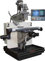
Computer numerical control (CNC) machines have been in use in industrial applications for nearly 30 years. These machines use lathes, mills, or turning centers and control them with computer control similar to robot axis control. ill. 1 shows a CNC mill. The mill has a bed that travels right and left (the X-axis) and toward and away from the operator (the Y-axis). A spindle motor that holds the cutting tools is mounted above the table and it moves up and down to control the depth of cut, which is the Z-axis. These three motions allow the mill to cut parts in three dimensions (XYZ). In other words, the CNC mill will operate very similarly to an XYZ robot.
Since the CNC mill has three axes, it will use three-axis amplifiers and three servomotors. The axis amplifiers and servomotors are similar to those found in robots. The CNC mill may also have variable-speed control on its spindle motor. The speed of the spindle motor can be controlled through gears as well as variable-speed control to control the cutting speed of the tools.
The CNC machine program will be similar to the XYZ program except that the CNC program usually has many more service codes than the robot. For instance. a CNC mill has service codes to turn on the spindle, to turn on the coolant, to open and close the chuck, and other codes that control the program. ill. 2 shows an example of a CNC program.
Some CNC equipment such as the Fanuc GE controllers incorporate motion control, velocity control, and positioning control in one part of the controller, and a programmable logic controller (PLC) in a second section of the controller. This arrangement allows data from the motion controller to be passed to the PLC to energize outputs such as clamp-close solenoids and conveyors or parts feeding systems and read input signals from limit switches, proximity switches, and photoelectric switches to indicate a part is ready to be loaded into the mill or a part is ready to be removed from the mill.

Above: ill.1 A CNC
N1;THIS PROGRAM IS FOR USE ON THE BRIDGEPORT MILL
N2G7 X0.7525Y0.512ZO.SF80. N3G I Z0.1 F60. N4G1Y0.2553
NSGIZO.SF80.
N6G 1X0.9836Y0.4864 N7G 1 Z0.1 F60. N8G7 XL035Y0.512 N10G1X1.1377
N l 2G 1 X 1.189 I Y0.4864 N14G 1 Y0.435 N16G 1 X0.9836Y03066 N18G7 Y0.2553
N20G 1 X 1.189 I N21G 1 ZO.SF80. N22G I X 13174 N23G 1 Z0.1 F60. N24G1
XL5229Y0.512 N25G 1 ZO.SF80. N26G1X1.7026Y0.3836 N27G 1 Z0.1 F60. N231
G 1 ZO.SF80. N234GOM30 ;END
Above: ill.2 A typical program.
| Top of Page | PREV: BASIC Programs and C Programs | NEXT: Basic Parts of Industrial Robot Systems |