AMAZON multi-meters discounts AMAZON oscilloscope discounts
ill. 1 shows an example of a typical amplifier for an AC robot motor. The motor for this circuit is a three-phase AC motor. It has a DC generator that acts as a tachometer, which is directly connected to the shaft of the AC drive motor. An encoder is also connected to the AC motor shaft to provide positional data.
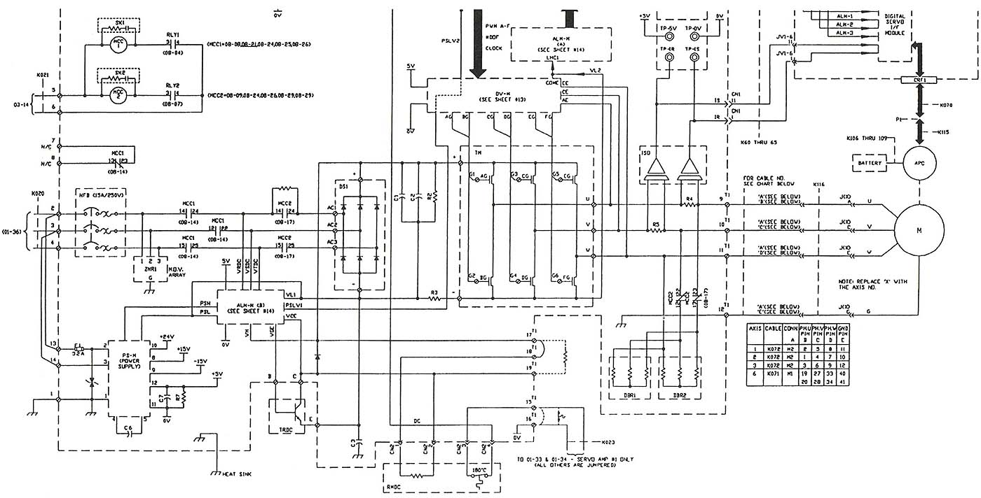
Above: Electronic schematic of an AC amplifier for
three-phase AC drive motor. CLICK HERE
or image for larger size.
From the diagram in ill. 1 note that the AC amplifier looks similar to the diagram for the variable-frequency drive. The amplifier is powered with three-phase voltage on the left side of the diagram. The three-phase voltage wires are connected to a three-phase circuit breaker to provide over-current protection for the motor. It's important to note at this time that the circuit breaker provides physical protection, and the logic and fault circuits in the robot take samples of the current and voltage that the motor uses and interrupts all voltage to the motor if the current becomes too large and if the voltage is too high or too low. The value of the setpoints for the voltages and currents can be programmed through the teach pendant so that the levels can be adjusted to each application for the robot.
The voltage from the circuit breaker is sent to the three-phase bridge rectifier circuit. The bridge rectifier changes the three-phase AC voltage to DC voltage. A set of capacitors and an inductor are provided with the rectifier to filter the pulsing DC to pure DC. The DC voltage is provided to the output transistors as a bus. From the information about the AC variable-frequency drives that the diodes in the three-phase rectifier are mounted in molded plastic and are installed in the circuit as a module so that individual diodes can't be replaced. Rather the entire module must be replaced if a problem occurs with any of the diodes.
The transistors in the output section of the amplifier are used in a circuit to create an AC sine wave for the motor that's similar to the sine wave provided by an AC alternator. Refer to diagrams that show the AC waveforms for the variable-frequency drives to see how the transistors are switched on and off to provide the sine wave. Notice in ill. 1 that the transistors are mounted in pairs. The top transistor of each pair provides + (positive) DC voltage that's used to make the positive part of the sine wave, and the bottom transistor of each pair provides - (negative) DC voltage that's used to make the negative part of the sine wave.
The transistor pairs are mounted in a module so that they can be easily removed and replaced when they become faulty. The transistors in the amplifier output section may be insulated gate bipolar transistors (IGBTs) or they may be Darlington pairs. The base of each transistor is controlled by the base drive circuit that's shown directly above the transistors. The base drive circuit receives its signals from the axis drive board that converts all of the positional data signals from the processor to motor speeds, number of pulses (how long the motor should remain energized), and acceleration and deceleration ramps. The base drive circuit receives feedback information about motor current requirements and adjusts the base signal to each transistor to ensure that each motor receives the proper amount of torque to move its load smoothly.
The AC motor is shown in this diagram connected to the output of the
transistor drive circuit. It's important to remember that the amplifier
circuit is mounted in the servo axis board that's located in the main
robot cabinet, and the motor is mounted in the robot axis. A large cable
is provided for each motor on the robot that connects the three-phase
voltage from the servo axis module to the motor. The connection at the
robot uses threaded military-type connectors called cannon plugs so that
the cable can be quickly and easily removed and replaced any time a motor
must be removed.
| Top of Page | PREV: DC Amplifiers | NEXT: Acceleration and Deceleration of AC and DC Servomotors in Robots |