| PREV: Timing and Counting Values Beyond 9999 | NEXT: Other Sequencer Functions |
The carbon brush manufacturing process must control the mixing of several ingredients. The mixing and blending process occurs in a very specific sequence. Since this operation is sequential, it will be easier to control it with the SLC 100 sequencer instruction (see Fig 3-21 below ). From this example you can see that the sequencer instruction looks like a timer in the program except its mnemonic is 500. The sequencer also uses a reset (RST) like the timer and counter. To fully understand the sequencer, you need to see that it controls its outputs like a matrix that's made of columns and rows (see ill. 22 below).
AMAZON multi-meters discounts AMAZON oscilloscope discounts 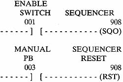
ill.21: Example of the sequencer instruction for the SLC
100.
![]()
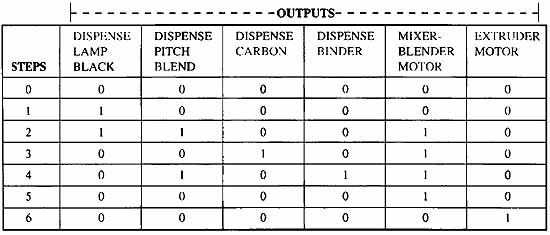
ill.22: Example of the matrix for a sequencer instruction. The
outputs represent the solenoids and motor starters for the mixing part
of the carbon brush manufacturing system.
The sequencer instruction in ill. 22 is filled in to represent the industrial mixing application of the carbon brush manufacturing process. Since carbon brushes are made from four raw materials (lamp black, pitch blend, carbon, and binder), the system has four solenoids that control dispensing these materials. The mixing system also has two major motors: the mixer/blender and the extruder motor. Each of these six outputs is identified across the top of the matrix.
Seven steps in the process are identified down the left side of the matrix. The process begins with the zero step, which is used to reset and start the process. You should notice that all the outputs are turned off at this point by placing a zero in each column. When the sequence begins, an internal timer is used to drive the sequencer and ensure that each step lasts for 3 minutes. Step 1 is the start of the process and the lamp black dispensing solenoid is energized for 3 minutes.
At the end of 3 minutes, the timer times out and sends a signal to the sequencer that advances it to step 2. During step 2 you will notice that the lamp black solenoid remains on, and that the pitch blend dispensing solenoid and the mixer motor starter are energized to start mixing the product. The amount of lamp black in the product requires that its solenoid remains on for 6 minutes (two of the sequencer steps). If it was required to be on for a longer period of time, additional steps would be inserted to ensure it remained on for the correct amount of time. The amount of time delay that's used in the timer is the lowest unit of time that any one step requires.
When the timer times out and moves the sequencer to step 3, you will notice that the lamp black and the pitch blend solenoids are turned off, but the mixer motor remains energized. The carbon solenoid is also energized during this time, which allows carbon to be dispensed while the mixing is occurring. This causes the product to be mixed and blended thoroughly.
When the sequencer moves to step 4, you will notice that the pitch blend solenoid is energized again. Now the binder solenoid is energized so that binder is blended with the product as it's continually mixed. At the end of this 3-minute period, the timer advances the sequencer to step 5 where all of the solenoids except the mixer blender motor are de-energized. At this step the mixer continues to be energized, so the product is continually mixed for an additional 3 minutes.
In the final step, the extruder motor starter is energized and it begins to turn a large fluted screw, which forces the material out through a die. This process is called extrusion and it ensures that all of the brushes are the same width. A knife blade continually cycles so that each carbon brush is cut to the same size. The carbon brushes drop onto a metal conveyor belt where they are moved into the oven for the curing process. You should remember that all of the logic in the controller prior to the sequencer is used to control the conveyor and oven. When the sequencer ends step 6, the sequencer is reset to step 0 where all the outputs are de-energized until the process is ready to start again.
Programming the Sequencer Matrix into the SLC 100
The matrix is divided into three major sections that are identified across its top row: bit address data, program code, and preset values. Each of these sections is discussed separately. ill. 23a shows each of these sections for the sequencer instruction. ill. 23b shows a sequencer instruction completely filled in.
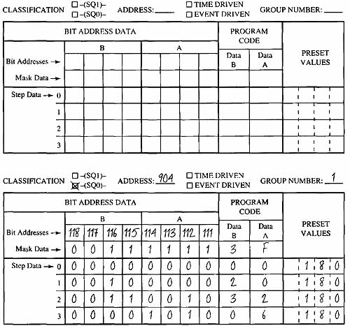
ill.23: (a) Diagram of the sequencer instruction with the
three major sections highlighted. The major sections are the bit
address data, the program code, and the preset values. (b) Example
of the sequencer instruction completely filled in for the carbon
brush mixing operation.
In batch-mixing applications, the sequencer will control six outputs 111—116 as bit addresses. These are the addresses to which the solenoids and motor starters are connected. The sequencer knows that the outputs are going to be addresses 111—116 because the person who enters the program uses the table in ill. 24 to locate the output addresses. You can see from the table that the output addresses are placed into groups of six real outputs and two internal outputs. It is important to use the addresses of only one group in any one sequencer instruction and to use them in the order of least significant bit (LSB) address in the rightmost column.
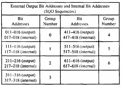
ill.24: A table showing the output addresses assigned to each
group number for a sequencer. External Output Bit Addresses and Internal Bit Addresses (SQO Sequencers). Bit Addresses; Group Number
In the example in ill. 23b you can see the programmer entered addresses 111—116 in the matrix instruction under the column of Bit Address Data, and in the row marked Bit Addresses. If the outputs were to be connected to addresses 211—216, the programmer would have entered these numbers in this part of the sequencer matrix. Since this application only requires six outputs to control its solenoids and motor starter, only one group needs to be selected. If more than eight outputs were needed, a second group would have to be selected and it would be controlled by a second sequencer.
Selecting a Mask for the Sequencer
The next step of the programming process is to select a mask for the outputs. The mask is a set of l’s and U’s that's placed in the matrix in the row directly below the Bit Address row, which indicates the addresses you are placing under control of the sequencer. If you only needed four of the outputs to be controlled by the sequencer, you could place a 0 in the mask of the other outputs. Then they would not be controlled by the sequencer and they could be used in the ladder logic as needed. The 1’s and 0’s in the mask are actually ANDed logically with the number addresses listed above it. This means that if a 1 is placed in the mask directly under address 111, output 111 will be controlled by the sequencer. If a 0 was placed in the mask directly below address 112, it would mean that address 112 would not be used by the sequencer. (Note: In the SLC 100 the mask is placed in the sequencer during the programming phase of the project and it's normally not changed.)
The mask is determined by a four-digit hexadecimal number shown in ill. 25. From this table you can see that the numbers use binary l’s and 0’s to represent numbers 0—15. Since the hexadecimal system uses a single value to represent all of the numbers, the letters A—F are used to represent the two digit numbers 10—15. Once you have determined the l’s and 0’s to correspond with the outputs you want to have energized and de-energized, you can use the table to convert this value to its hexadecimal equivalent. The hexadecimal number is then placed in the sequencer matrix in the row marked Mask Data under the column marked Program Code (Data B and Data A). You should notice that since addresses 111—114 are listed under column A, and addresses 115—116 are listed under column B, the mask for addresses 111—114 should be placed in Data A column and the mask for addresses 115—116 should be placed in Data B column.
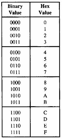
ill.25 : Hexadecimal numbers used to represent the mask for
the sequencer. Hex Mask and Hex Data Codes (for personal computer
software data form).
Setting the Time for Each Step of the Sequencer
In our example for mixing and blending the products to make the carbon brushes, we set each step to last for 3 minutes. The value for the time delay is placed in the column in the matrix that's identified as Preset Values. The time must be listed in seconds. Since the example needed 3 minutes, the value 180 would be entered into the column for each step to represent the 3 minutes of time required. The timer that keeps track of this time delay is integrated as an internal part of the sequencer instruction and no additional external timer is required. The time delay for each step does not need to be the same amount of time.
| Top of Page | PREV: Timing and Counting Values Beyond 9999 | NEXT: Other Sequencer Functions |