| PREV: Typical Problems a Technician will Encounter with PLCs | NEXT: Documenting a PLC Program with Software |
AMAZON multi-meters discounts AMAZON oscilloscope discounts
If you are technician, you may find it necessary to work on other PLCs such as the Allen- Bradley PLC2. This mid-sized PLC is very common in industrial applications. When you troubleshoot a limit switch that's connected to a terminal on one of the input modules, or a motor starter that's connected to a terminal on one of the output modules, you will need to know how to decode its address to find the correct status indicator on the correct module. The address for each input and output is defined by the location of inputs and outputs in the permanent internal memory of the PLC2. A memory map for the permanent memory for the PLC2 is shown in ill. 32.
AMAZON multi-meters discounts AMAZON oscilloscope discounts 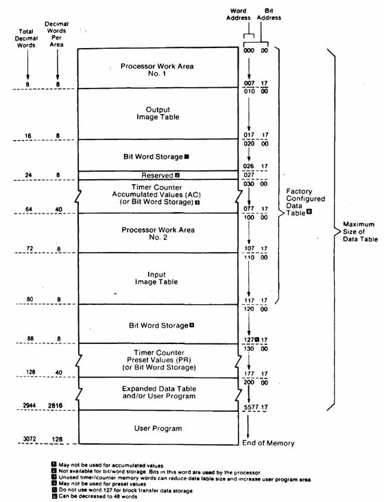
ill.32: Example of Allen-Bradley PLC2 memory and data
table.
From the diagram in this figure, you can see the first section of memory is called Processor Work Area 1, and this area is used only by the processor. The output image table is located at address 010 to 017 (octal). The input image table is located at address 110 to 177 (octal). These addresses will also be assigned to the coils and contacts in the program. The remainder of the memory map will be discussed later, but first you need to know that the numbers 010—077 and 110—177 are also used to decode the rack, module, and terminal location for each input and output. This information will also indicate where you would find the field wiring connected to a specific terminal.
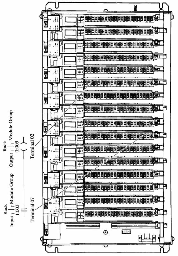
ill. 33 shows a typical address for a limit switch connected to terminal 110/03 and a motor starter connected to output 011/06. From this figure you can see that the first three digits of the input are 110. The first 1 in the address indicates that it's an input address. The second 1 indicates the address is located in rack 1, and the 0 indicates the module is located in module group 0 in the rack.
Notice that the PLC2 processor is mounted in the far left slot of the rack. In the addressing scheme, the first slot is dedicated to the processor and it's not counted as one of the rack addresses. The remaining slots are paired for addressing purposes and are called module groups. The module groups are numbered 0—7 and their numbers are indicated across the top of the rack. The number 03 in the input address indicates the limit switch would be connected to terminal 03 on the module. Since the addresses use the octal numbering system, terminal 03 is actually the fourth terminal on the module. An arrow indicates the exact location for the address of the limit switch.
The example in ill. 33 shows the address for the output in this circuit is 011/06. The same addressing scheme is used. The first 0 in the address indicates the address is for an output. The first 1 in the address indicates the module is located in the second module group, which is number 1. (Remember that the addresses for an octal numbering system start at 0.) The terminal number for this output address is 06, which is the seventh terminal on the module.
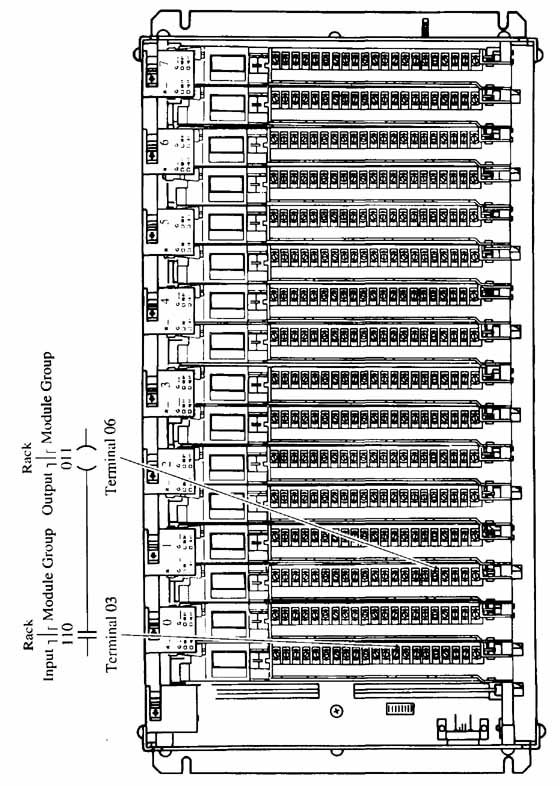
ill. 33 : Allen-Bradley PLC2 addressing system for an input and an
output.
To fully understand all of the addresses in the PLC2 memory map and in the addresses of input and outputs, you need to know that the PLC2 can have a maximum of seven racks that will be numbered 1—7. The racks are available in several sizes for 2 slots, 4 slots, 8 slots, and 16 slots. This means the system has the possibility for module groups for the largest rack and the groups will be numbered 0—7. Since each module group in the rack has two slots which will each accommodate one module, the numbering system must indicate whether the terminal number in the address is for the module in the left or right slot of the module group. The numbers for the terminals on the module that's in the left slot of a module group are 0—7, and the numbers for the terminals on the module in the right slot are 10—17. Since the PLC2 uses the octal numbering system, numbers 8 and 9 are not used.
Now when you refer to the memory map for the PLC2, you will see that the addresses for the outputs and inputs are an exact copy of the rack, module group, and terminal addresses used to determine the physical location of the module in the rack. In fact address 010 in the memory map is called Output Image Table for Rack 1, and address 020 is called Output Image Table for Rack 2. It is important to remember that the term image table is used because the PLC2 processor keeps an updated copy of a 1 or 0 in this area of its memory to indicate if an input or output is on or off. If the PLC uses only one or two racks, which is very typical, the remainder of the input addresses 130 through 170 and output addresses 030 and 070 can be used for other purposes such as storing the preset and accumulative values for timers and counters. Additional memory locations are available at ad dresses above 200. The total number of memory addresses above 200 will depend on the size and amount of memory that's purchased and installed in the PLC. The user program consisting of contacts and coils that determine the program logic is stored in the user program area at the bottom of the memory map.
Allen-Bradley PLC2 Addressing System
The addressing system for the PLC2 is more complex because this system can have multiple I/O racks and a variety of input or output modules in each rack. The racks provide a means of mounting modules so that they can quickly be removed and replaced in case of a failure. The electrical wiring for each input or output is connected to a wiring arm that makes connection on the front of the module. The wiring arm can swing out of the way to allow the module to be removed and replaced from the rack. In this way, no changes in the wiring are required when a module is replaced. The rack also provides a means to connect each module to a bus that allows data to be passed from the microprocessor to each module. The bus connection is on the back edge of each module. When the module is placed into the rack and seated into the edge connector, it will automatically be connected to the processor bus.
ill. 33 shows examples of addressing an input and an output. You should remember from the discussion in the previous section that the numbers in the address will indicate four distinct features of each signal: whether the signal represented is an input or an output, the rack the module is mounted in, the slot within the rack where the module is mounted, and finally the terminal on the module where the device is connected. All of this information is necessary for both the computer and the technician. The computer must know where the input signals are coming from and where output signals are going. The technician must also know where the specific input or output module is physically located in the rack to take a voltage reading.
Allen-Bradley SLC 500 and PLC5 Addressing Systems
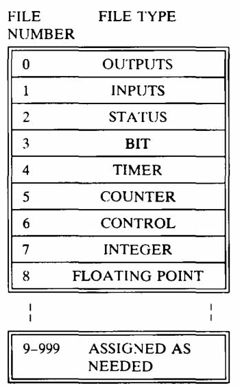
The Allen-Bradley SLC 500 and PLC5 use a memory structure that's nearly identical to each other and it's similar to the PLC2 system. The main difference between the PLC2 and the PLC5 and SLC 500 memory maps is that more of the memory is dedicated for specific purposes in the PLC5 and SLC 500. ill. 34 shows an example of the memory map for the PLC5 and SLC 500 systems. From this figure you can see that the PLC5 and SLC 500 can have a maximum of 1000 files numbered 0—999. The first eight files are dedicated, and the remaining memory can be assigned for the user program and for additional locations for any of the eight types of files except inputs and outputs. This provides a great deal of flexibility in assigning memory addresses to files. The memory types are: outputs, inputs, status files, bit files, timer files, counter files, control files, integer files, and floating- point files. The other major difference between file addresses in the memory of the PLC5/SLC 500 and the PLC2 is that the PLC5/SLC 500 addresses use the decimal numbering system and the PLC2 uses the octal numbering system.
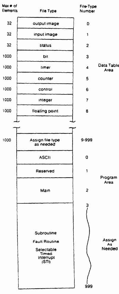
ill.34 : The memory map for the Allen-Bradley SLC 500 and PLCS. Data Table Area. Subroutine; Fault; Routine; Selectable Timed
Interrupt (STI)
The files in the PLC5/SLC 500 also are assigned file-type numbers. ill. 35 shows an example of the memory for the SLC 500 and the PLC5. From the figure you can see the files are named for the type of values that are stored in them. E.g., the output file is number 0 and it contains all of the output image register addresses. These are the addresses for all of the hardware output modules. The input image register is stored in file 1 and it provides a similar function for all of the input addresses.
ill.35: Example of Allen-Bradley PLC5 and SLC 500 data files.
The first nine files are assigned by the processor and will always have the assigned number. When an address is used in the program a key letter is used with the file type to define the addresses within the file. E.g., all timer functions that use a timer file address would use the key letter T and the number 4 as in T4. The remainder of the key letters are as follows: output = O, input = l, status=S, bit=B, timer=T, counter=C, control=R, integer=N, and floating point=F. If additional files are required, the key letter is used and any file number above 10 can be assigned.
ill. 36 shows an example of addressing inputs and outputs for the PLC5. This addressing system is similar to the previous systems except that the letter I is used as the first part of an input’s address, and the letter 0 is used for the first part of an output’s address. The remainder of the SLC 500 and PLC5 address that describes the location of the rack, module group, and terminal number is similar to the PLC2. The main difference in the PLC5 is that two digits are reserved for rack addresses since the PLC5 can have a maximum of 64 racks numbered 0—77 (octal).
ill. 36: Allen-Bradley PLC5 addressing system for an input and an output.
You should notice that the programming areas of the PLC’s memory are also shown in this diagram. The programming areas of memory include program 0, which is the area for ASCII, program 1, which is reserved by the processor, program 2 where the main program is stored, and the remainder of the memory where the subroutines and fault routines are stored. The PLC5 and SLC 500 can have a number of separate programs stored in the main program area, but you should remember that the processor executes all of the programs in the main program area of memory as one large program.
Allen-Bradley SLC 500 and PLC5 Hardware
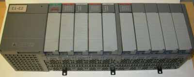
The PLC5 is used in many industrial applications. In modern industrial facilities, the amount of space for electrical control cabinets on the factory floor is limited because more space is needed for production or process equipment. This means that the size of PLC controllers and modules must be as small as possible. The SLC 500 is much smaller than the PLC5 since it uses hardware that's similar in size to the SLC 100. ill. 37 shows a typical PLC5 system installed in a rack, and ill. 38 shows a picture of the SLC 500 system. Both systems can use software that resides on a personal computer and the SLC 500 can use a hand-held programmer for making changes to its program. The hand-held programmer is also shown in ill. 38.
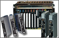
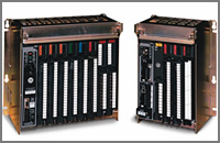
ill.37: A PLC5 processor in a rack with I/O modules.
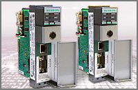
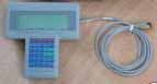
ill.38: A variety of Allen-Bradley SLC 500 programmable controllers
with input and output modules. A hand-held programmer is also shown.
| Top of Page | PREV: Typical Problems a Technician will Encounter with PLCs | NEXT: Documenting a PLC Program with Software |