| Home | Sitemap/Articles |
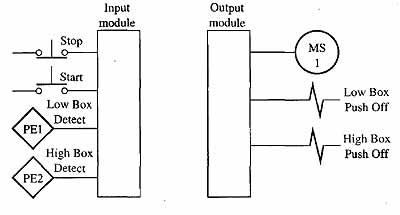
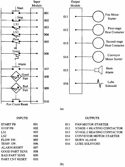
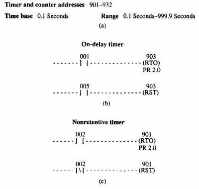
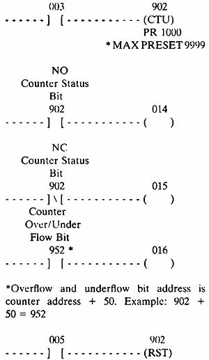
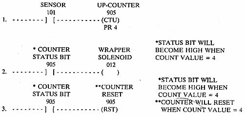
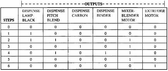
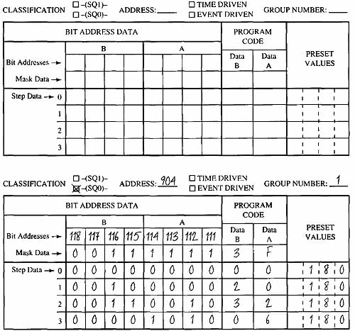
AMAZON multi-meters discounts AMAZON oscilloscope discounts You are a technician who has been assigned the job of converting a machine that's presently con trolled by relay logic and motor-driven timers so that it will be controlled by a programmable logic controller (PLC). The machine also has a drum switch with a number of cams used to energize a group of solenoids in a machine sequence. The drum switch should be replaced by a sequencer instruction in the PLC. Your assignment includes providing a printout of the ladder logic diagram and a full set of drawings including the switches and outputs connected to input and output modules. Your supervisor will tell you the brand of PLC you will be using and the addresses for the inputs and outputs you should use. Your supervisor will also provide the original relay logic diagram. AMAZON multi-meters discounts AMAZON oscilloscope discountsSolutions to Job AssignmentYou were assigned to convert a machine that's operating on relay control to be controlled by a PLC. Your teacher should supply the original diagram. The first step of your solution should be to identify each input switch and identify its type. The inputs should then be assigned an address and a diagram similar to the one in ill. 5 or the diagram in ill. 16 should be prepared that shows all inputs and outputs that the system will need. The next step of your solution should include a step-by-step conversion of the relay logic to PLC ladder logic. Since the original machine used relay logic, the conversion should be rather simple. If the machine has timers or counters, you will need to assign a number for each PLC timer and counter that you will need. The preset value of each timer and counter should also be determined, and the condition that will be used to reset each should be identified. When you are ready to program the timer and counter into the program, use the examples in Figs. 3-17, 3-18, and 3-19. If your solution uses a sequencer, you will need to list all of the outputs for the sequence in the order that they need to be energized. Figs. 3-22 and 3-23 can be used as examples for your sequencer instruction. Be sure to include all of the drawings and documentation for your program with your solution.
|
Monday, August 25, 2008 13:13