AMAZON multi-meters discounts AMAZON oscilloscope discounts
A more complex application of a closed-loop control system is a motion control system that has a positioning loop and a velocity loop. ill. 1 (below) shows an example of this type of motion control loop used to drive a servomotor that moves a welding index table. The servomotor in this application has an encoder attached to its shaft that's used to provide velocity data as well as positioning data. The pulse train from the encoder is sent to the frequency-to-voltage converter, and the output voltage signal from the converter is sent to the summing junction. A position setpoint is set in the up/down counter, which is converted from a digital value to an analog voltage. The voltage is sent to the summing junction as a reference signal. The summing junction compares the position reference signal to the velocity feedback signal and produces an error signal that's sent to the op amp as the inverting input signal. If the error is negative, it means the motor hasn't moved the table into the correct position, and additional voltage will be sent to the motor from the output signal from the op amp. The output signal from the op amp must go through a pulse-width modulator (PWM) circuit, a control logic circuit, and a motor control circuit.
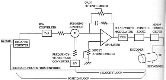
Above: ill. 1: Block diagram of a servomotor
used to control the position of an index table for a welding application.
This diagram shows an encoder that's used to provide a velocity and position feedback signal.
When the motor shaft moves the table, the encoder will indicate that the table is at a new position. The position loop compares the setpoint position (the desired position) in the up/down counter buffer with the actual position that's reported by the encoder. The amount of difference is converted from a digital signal to an analog voltage and sent to the summing junction. The velocity loop compares the amount of actual error to the amount of possible error and determines how close the indexing table is to its destination. The closer the table gets to its destination position, the smaller the amount of signal voltage is sent to the op amp and to the motor and it will slow the table. When the encoder indicates that the indexing table is at the correct position, the setpoint signal and the feedback signal will cancel each other and the resulting signal value will be zero, which means that no voltage is sent to the motor so it will stop at that position.
PREV: Simple Analog Servo Positioning System | NEXT: Quiz
HOME