AMAZON multi-meters discounts AMAZON oscilloscope discounts
The valve positioning system in ill. 1 shows an electrical system that's combined with an op amp to provide a signal to a current to pressure (I/P) transmitter. The transmitter receives a 0-10 volt signal and sends a 3-15 psi air signal to open or close a water valve. When the valve is opened, additional water will flow into the tank and change the level of the float that's used as a sensor to indicate the water level in the tank. The water level in the tank is the PV for this system, and the valve is the output device.
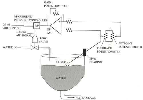
Above: ill. 1 Diagram of a servo system that controls the level of water
in a tank.
The SP and PV (feedback) signal are both connected to movable arms on potentiometers. The voltage from these two potentiometers is used as the input for an op amp. The op amp is used as an error amp and its gain can be determined by the size of the feedback resistance and the input resistance. The SP is entered for the system by adjusting the SP potentiometer. Since the voltage from that potentiometer will be different from the voltage that comes from the feedback potentiometer, the op amp will send a signal to the I/P transmitter that indicates the amount of error.
When the I/P transmitter receives the error signal, it will send a change of air pressure to the valve, opening farther to allow more water to flow into the tank, and the tank level will increase. When the tank level starts to increase, the float will rise and change the position on the feedback potentiometer. The voltage from the feedback potentiometer will increase, the amount of difference between the SP voltage and the feedback voltage will become smaller, and the output signal will decrease.
When the feedback signal becomes the same voltage as the SP signal, the error will be zero. Since the error is zero, the voltage to the valve would become zero. The valve for this application must hold its position when voltage is at zero, and it will increment (add to the position) or decrement (subtract from the position) anytime the valve position is increased or decreased.
The rate of response can be controlled by changing the amount of gain. This means that a variable resistor (potentiometer) is used as the feedback resistor on the op amp and it's called the gain pot. If the resistance of the potentiometer is increased, the gain will increase and the response will be faster.
PREV: Bumpless
Transfer
NEXT: How
Fast Controllers Will Change the Output