AMAZON multi-meters discounts AMAZON oscilloscope discounts
INTRODUCTION:
Each year 120-V circuits cause more deaths and injuries than circuits of all other voltage levels combined. Such low-voltage circuits are extremely hazardous for two reasons. First, low-voltage circuits are the most common. Because they are the final distribution voltage, 240-V and 120-V circuits are used throughout residential, commercial, industrial, and utility systems.
The second reason for the extreme danger of low-voltage circuits is user apathy.
Comments such as "It can't hurt you; it's only 120 volts" are heard all too often. Reference to TBL. 1 shows that 120-V circuits can produce currents through the human body that can easily reach fibrillation levels. Consider a perspiring worker using a metal electric drill with one foot immersed in water. TBL. 1 clearly shows that under such conditions, a worker can be subjected to a lethal shock. Furthermore, if sustained for a sufficient period, 120-V contact can create severe burns.
A 480-V circuit is more than four times as lethal as a 120-V circuit. A 480-V circuit has sufficient energy to sustain arcing faults and to create severe blast conditions. This section summarizes some of the safety-related concerns that apply to low-voltage circuits-that is, circuits of 1000 V ac and less and 250 V dc and less. Generally, workers should treat low-voltage circuits with the same degree of respect afforded medium- and high-voltage circuits. Refer to sections. 3 and 4 for detailed information. Note that some of the safety related information covered in this section also applies to medium-voltage and high voltage systems. Where necessary, the information is repeated in Section 11.
Electrical safety requirements when working on or near electronic circuits can be a problem. For example, the dictates of electrical safety would seem to require that circuit parts and workers be insulated from one another. In some electronic circuits, however, the prevention of static electricity damage requires that the worker be grounded. Also, many workers develop a sense of false security believing that 12,000 V in an electronic circuit is somehow less hazardous than 12,000 V in a power system. This section will also present and explain the electrical safety procedures to be employed when working on or near electronic circuits.
===
TBL. 1 possible Current Flow in 120-V Circuit
Body part Resistance, Ohm, Wet hand around drill handle 500 Foot immersed in water 100 Internal resistance of body 200
Total resistance 800
Total current flow possible in 120-V circuit = I = (120/800) = 150 mA
===
LOW-VOLTAGE EQUIPMENT
Hand tools and extension cords are the most commonly used pieces of low-voltage equipment. Each of these items is responsible for hundreds of injuries and deaths each year.
The following sections summarize the types of usage procedures that should be employed with such equipment.
===
TBL. 2 Visual Inspection points for Extension Cords and Cord-Connected Tools
• Missing, corroded, or damaged prongs on connecting plugs
• Frayed, worn, or missing insulation
• Improperly exposed conductors
• Loose screws or other poorly made electrical connections
• Missing or incorrectly sized fuses
• Damaged or cracked cases
• Burns or scorch marks
===
TBL. 3 Recommended periodic Tests and Test Results for Extension Cords
Test Description pass/fail criteria Ground continuity test 25 A minimum is passed through Voltage drop across the cord the cord's ground circuit. Should not exceed 2.5 V.
Insulation breakdown High voltage is applied to the Leakage current no more than cord's insulation system and 6 µA @ 3000 V (500 M-ohm).
The leakage current or insulation resistance is measured (3000 V maximum direct current applied).
==
Extension Cords
Flexible cord sets (extension cords) are used to extend the reach of the power cord for low voltage-operated tools and equipment. They typically have a male plug at one end and a female receptacle at the other. The tool's power plug is inserted into the female receptacle, and the extension cord's male plug is inserted into the power source or into yet another extension cord's female receptacle. Extension cords can be used to supply power to tools that are located many meters away from the source of power.
Extension cords can be extremely hazardous if not used properly. The following precautions should always be observed when using extension cords:
• Closely inspect extension cords before each use. TBL. 2 lists the types of items that should be looked for during the inspection. (Note that TBL. 2 applies to both extension cords and portable tools.)
• Never use an extension cord or power cord to lift or support a tool.
• Make certain the ground connection is complete from one end of the cord to the other.
• Never alter the plug or receptacle on an extension cord. This applies especially to altering or removing the ground connection.
• If the extension cord is of the locking or twist-locking type, the plugs should be securely locked before using the cord.
• Do not use an extension cord in wet or hazardous environments unless it is rated for such service by the manufacturer. If extension cords are used in wet or hazardous environments, insulating safety equipment such as rubber gloves with appropriate leather protectors should be used.
• Only personnel who are authorized and trained in the use of extension cords should be allowed to use them.
• Extension cords should be subjected to the electrical tests outlined in TBL. 3. If the cord fails any of the listed tests, it should be replaced or repaired.
• When not in use, extension cords should be carefully rolled and stored in such a way that they cannot be damaged.
• Extension cords should never be used for permanent power installations. If power is required for more than the short duration, permanent electrical installation should be used. The maximum allowed is generally 90 days for seasonal types of installations, such as Christmas lights and other types of decorations.
• All temporary power connections in industrial and commercial facilities should be supplied from a circuit protected by a ground-fault circuit interrupter (GFCI). Alternatively, the cord itself should be equipped with a GFCI. (See Section 3 for more information on GFCIs.) An extension cord that exhibits any of the visual inspection problems listed in TBL. 2 or that does not pass the tests listed in TBL. 3 should be removed from service until it can be repaired or replaced.
Electric Hand Tools
Electric hand tools generally fall into one of three categories:
1. Metal tools with ground
2. Double-insulated types of tools
3. Battery-powered tools
Metal Tools with Ground. Metal tools are equipped with a three-conductor power cord.
FIG. 1 is a pictorial diagram of such an assembly. The three conductors are the hot (or line), the neutral, and the safety ground. The hot wire and the neutral wire form the actual power circuit of the tool. The safety ground is connected to the metal frame of the tool. If the hot wire is short-circuited to the case of the tool, the safety ground wire forms a continuous, low-impedance path back to the service box. In this situation, the worker will form a parallel path to ground, causing current to flow through the worker's body. Metal tools should always be connected to the power through a GFCI.
Double-Insulated Tools. Even the relatively low-impedance path provided by the safety ground in a metal tool can create lethal voltages from the hands to the feet. The double insulated tool does not employ a metallic case. Instead, its case is made of a high-strength, nonconductive plastic or composite material. The power connection for such tools is a two conductor power cord with no safety ground. Since the tool case is nonconductive, the user is protected by both the case and the normal insulation of the electric circuit. The double insulated tool can still present a shock hazard if it is dropped in water or if water enters the case. Because of this fact, many companies and workers have opted for the battery-powered tools described below.
Battery-Powered Tools. FIG. 2 is a photo of a typical battery-powered tool. This battery-powered drill (also a driver and hammer) is powered by an 18-V rechargeable battery. Heavier-duty battery-powered tools for use in industrial and construction environments will normally have higher-voltage batteries for reduced current and longer life. Most workers have two or three batteries that are kept fully charged for backup. When the tool battery runs down, it takes only seconds to replace it with a fully charged backup.
Because the battery-powered tool is not connected to an ac power circuit, and because it has an insulated case assembly, it is considered to be intrinsically safe from an electrical hazard standpoint. However, battery-powered tools are physically dangerous and must be handled properly to prevent injury.
===
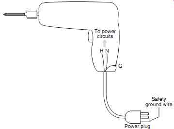 FIG.
1 Typical metallic case hand tool. To power circuits H N Power plug Safety
ground wire G
FIG.
1 Typical metallic case hand tool. To power circuits H N Power plug Safety
ground wire G
===
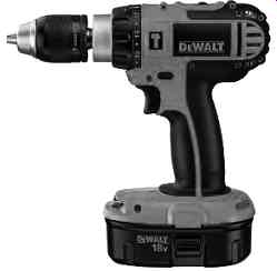
FIG. 2 Battery-powered drill.
Precautions for AC-Powered Tools. Both insulated case and metal case should be subject to the same types of precautions as those outlined for extension cords in the previous section. Specifically, the following should be observed:
• Closely inspect tools before each use. TBL. 2 lists the types of items that should be looked for during the inspection. (Note that TBL. 2 applies to both extension cords and portable tools.)
• Never use the tool power cord to lift the tool. If the tool must be lifted, tie a hand line or rope to the tool.
• Make certain the tool's ground connection is complete. For metal-cased tools, the safety ground connection is the difference between life and death when an internal short circuit occurs.
• Never alter the plug or receptacle on a tool. This applies especially to altering the ground connection.
• If a tool employs a twist-lock or locking type of plug, it should be securely fastened before the tool is used.
• Do not use a tool in wet or hazardous environments unless it is rated for such service by the manufacturer.
• If tools are used in wet or hazardous environments, insulating safety equipment such as rubber gloves with appropriate leather protectors should be worn.
• Only personnel who are authorized and trained in the use of power tools should be allowed to use them.
• Cord-connected tools should be subjected to the electrical tests outlined in TBL. 4. If the tool fails any of the listed tests, it should be replaced or repaired.
• When not in use, tools should be carefully stored in such a way that they cannot be damaged.
• All temporary power connections in industrial and commercial facilities should be sup plied from a circuit protected by a GFCI. (See Section 3 for more information on GFCIs.) Any tool that does not meet the pass/fail criteria listed in TBL. 4 should be removed from service until it can be repaired or replaced.
Current Transformers
The safety hazards of current transformers are identical for low-, medium-, and high-voltage circuits. Refer to Section 11 for a detailed coverage of the nature of current transformer hazards and methods for protecting workers from those hazards.
=======
TBL. 4 Recommended periodic
Tests and Recommended Results for Cord-powered Tools
Test Description pass/fail criteria
Ground continuity 25 A minimum is passed through
Voltage drop across the cord test the cord's ground circuit. Should not exceed 2.5 V.
Insulation breakdown High voltage is applied to the Leakage current not more than cord's insulation system and 6 mA @ 3000 V (500 M?).
The leakage current or insulation resistance is measured (3000 V maximum direct current applied)*.
Leakage test
Measures the current (0 to 10 mA) that would flow through the operator if he or she were to provide a path to ground at normal operating voltage.
Operational check
Operates the tool to verify proper
Operating current should be operation and to indicate within nominal nameplate operating current. Values.
* Refer to tool manufacturer's directions for allowed maximum test voltages.
=======
GROUNDING LOW-VOLTAGE SYSTEMS
The subject of electrical grounding is a complex one. The following sections focus on the grounding concepts and requirements of low-voltage systems as they relate to safety.
Section 5 of this handbook provides a much more in-depth coverage of electrical grounding principles and requirements. Also, the reader may refer to the various ANSI/IEEE standards including IEEE Guide for Safety in AC Substation Grounding (ANSI/IEEE standard 80) and IEEE Recommended practice for Grounding of Industrial and Commercial power Systems (ANSI/IEEE standard 142).
What Is a Ground?
A ground is an electrically conducting connection between equipment or an electric circuit and the earth, or to some conducting body that serves in place of the earth. If a ground is properly made, the earth or conducting body and the circuit or system will all maintain the same relative voltage.
FIG. 3a shows an electrical system that is not grounded. In such a situation, a voltage will exist between the ground and some of the metallic components of the power system. In FIG. 3b, the earth connection has been made. When the system is grounded, the voltage is reduced to zero between the previously energized sections of the system.
Note that FIG. 3 assumes that the earth is a perfect conductor. The earth is not a perfect conductor; consequently, a voltage drop may exist between the metal and the measurement point. This is covered in more detail in the Voltage Hazards sections below.
Bonding versus Grounding
Bonding is the permanent joining of metallic parts to form a continuous, conductive path.
Since the earth is generally not a good conductor, bonding is used to provide a low-impedance metallic path between all metallic parts. This, in essence, bypasses the earth and overcomes its relatively high impedance. A good grounding system is a combination of solid connections between metallic parts and the earth as well as between all metallic parts.

FIG. 3 Grounding. (a) Before system is grounded, a voltage exists between
the system and the earth; (b) when ground connection is made, no volt
age exists. (a) (b)
FIG. 4 Four voltage hazards related to system grounding.
Voltage Hazards
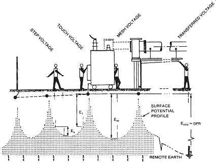
FIG. 4 illustrates the four standard voltage hazards that are associated
with and relieved by proper system grounding. If a system is ungrounded
and the non-energized metallic parts become energized, the metallic parts
will have a measurable voltage between themselves and ground. If the
system is grounded by driving ground electrodes into the earth, current
will flow from the rods into the earth. At each ground electrode, the
voltage will rise relative to the remote reference point. The voltage
will drop off away from the electrodes and peak at each electrode. This
situation creates the four types of voltage hazards as follows:
• Step voltage. As a worker steps across the ground, the front foot will be at a different potential than the rear foot. This effect is caused by the voltage gradient created by the ground electrodes ( FIG. 4). Step voltage can easily reach lethal levels. It can be mitigated by increasing the number of grounding electrodes, increasing bonding between the metal parts, and employing a grounding grid.
• Touch voltage. Because of the voltage gradient, the voltage of the earth only a short distance from the grounded metallic equipment will be different from the voltage of the equipment. Thus, if a worker touches the grounded equipment, his or her feet will be at a different potential than his or her hands. This voltage can be lethal. Touch voltage is mitigated by increasing the number of grounding electrodes, increasing bonding between metal parts, and employing a grounding grid.
• Mesh voltage. Mesh voltage is the worst case of touch voltage. Cause, effect, and mitigation methods are identical to those described for touch voltage.
• Transferred voltage. Because metal parts have a much lower impedance than the earth, the voltage drop between remote locations is lower on the metallic connections than the earth. This means that the earth may be at a significantly different voltage than the metallic connections. Transferred voltages are particularly noticeable on neutral wires that are grounded at the service point and nowhere else. Transferred potential can be mitigated by providing the entire area with a ground grid; however, this solution is infeasible in any but the smallest systems. Transferred voltage must be mitigated by avoiding contact with conductors from remote locations and/or using rubber insulating gloves.
======
TBL. 5 DC Circuits That Require Grounding
Circuits to be:
Type of circuit grounded Exceptions/comments Two-wire dc All Systems less than 50 V or greater than 300 V between conductors need not be grounded.
Limited-area industrial systems with ground detectors need not be grounded.
Certain rectifier-derived dc systems do not need to be grounded.
DC fire-protective signaling circuits with no more than 0.030 A may not need to be grounded.
Three-wire dc
All The neutral wire is grounded.
Note: See the current edition of the National Electrical Code for details.
======
TBL. 6 AC Circuits That Require Grounding
Type of circuit Circuits to be grounded Exceptions/comments
If maximum voltage to ground is less than 50 V AC systems
Three-phase, 4-wire wye, if neutral
The National Electrical Code has 50 to 1000 V is a circuit conductor many exceptions to these
Three-phase, 4-wire delta with grounding requirements.
Midpoint grounded on one leg
In some cases when grounded service conductor is uninsulated
Note: See the current edition of the National Electrical Code for details.
======
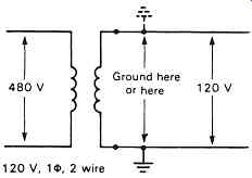
FIG. 5 Grounding a 120-V single-phase circuit.
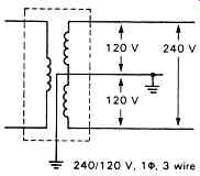
FIG. 6 Grounding a 240/120-V single-phase, three-wire circuit.
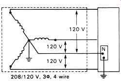
FIG. 7 Grounding a 208/120-V three-phase, four wire system.
===
System Grounds
What Is a System Ground? A system ground is the connection of one of the conductors to the earth. Such a connection is accomplished by connecting an electric wire to the selected system conductor and the grounding electrode.
Why Are Systems Grounded?
Power systems have conductors grounded for a variety of safety and operational reasons, including the following:
• Grounded systems provide sufficient short-circuit current for efficient operation of protective equipment.
• Grounded systems are less prone to transient overvoltages, which can cause insulation failures.
• Grounded systems are generally more easily protected from lightning.
• Solidly grounded systems are less prone to resonant conditions, which can cause equipment and insulation failures.
What Systems Must Be Grounded?
The NEC requires that both ac and dc systems be grounded. TBL. 5 summarizes low-voltage dc grounding requirements, and TBL. 6 summarizes low-voltage ac grounding requirements.
How Are Systems Grounded?
Electrical systems are grounded by connecting one of the electric conductors to earth. The conductor chosen and the location of the ground are determined as part of the engineering design for the system. FIGs. 5 through 10.8 illustrate four different low-voltage circuits and how they are grounded. Note that in some cases, the point of ground is determined by regulatory requirements such as the NEC.
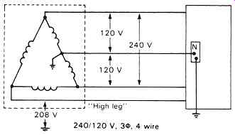
FIG. 8 Grounding a 240/120-V, three-phase, four-wire system.
The wire(s) that must be grounded depend on the voltage level and the system application. For dc systems, one of the conductors or the neutral wire is to be grounded depending on the type of system (TBL. 5). For ac systems, the NEC specifies five different locations for the selection of the grounding point. TBL. 7 identifies each of the five locations.
Systems with voltages between 480 and 1000 V phase to phase may be grounded through an impedance to limit the amount of fault current. In the circuit shown in FIG. 9, the resistor will oppose current flow between the earth and the phase wires. For example, assume that the phase A wire falls to the earth. The circuit that is formed will be composed of the power system's phase-to-neutral voltage (277 V) impressed across the series combination of the power system's impedances plus the grounding resistor. If the grounding resistor is properly sized, it will limit the fault current to any maximum value that is chosen during the design.
By limiting the amount of fault current, resistance-grounded systems provide a some what higher level of safety. However, the engineer making the design decision to ground through a resistor must take into consideration more variables than just safety. Protective systems, ground-fault current, voltage transients, and many other such concerns must be considered before the engineer decides to use a resistance-grounded system.
====
TBL. 7 Typical Grounding Requirements for Low-Voltage Systems
Type of premises wiring circuit, Location of ground; One-phase, 2-wire; Either conductor ( FIG. 5) One-phase, 3-wire; The neutral conductor ( FIG. 6) Multiphase with one wire common to all phases The common conductor (not illustrated);
Multiphase systems required on grounded; One of the phase conductors (not illustrated) phase Three-phase, 4-wire circuits; The neutral conductor (FIG. 7) 240/120, 3-phase, 4-wire; The center point of the grounded leg ( FIG. 8)
====
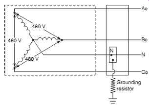
FIG. 9 Resistance grounded 480/277-V, three-phase, four-wire system.
Equipment Grounds
What Is an Equipment Ground? An equipment ground is an electrically conductive connection between the metallic parts of equipment and the earth. For example, transformer cases and cores are connected to the earth-this connection is called an equipment ground. Note that the non-current-carrying metallic parts of equipment are grounded and bonded together.
This bonding serves to reduce the voltage potential between all metallic parts and the earth.
Why Is Equipment Grounded? The equipment ground is one of the most important safety aspects of grounding. Workers are constantly in contact with transformer shells, raceways, conduits, switchgear frames, and all the other conductive, non-current-carrying parts. Proper equipment grounding and bonding ensures that the voltage to which workers will be subjected is kept to a minimum. Proper bonding and grounding mitigates touch and step voltages.
How Is Equipment Grounded? The NEC requires that the path to ground from circuits, equipment, and metal enclosures must meet the conditions listed in TBL. 8. The NEC does not allow the earth to be the sole equipment grounding conductor. Simply setting metal equipment on the earth is insufficient. Equipment must be connected to the earth via metal electrodes and conductors.
Equipment used in grounded systems is grounded by bonding the equipment grounding conductor to the grounded service conductor and the grounding electrode conductor. That is, the equipment ground is connected to the system ground. Equipment used in ungrounded systems is grounded by bonding the equipment grounding conductor to the grounding electrode conductor.
===
TBL. 8 Equipment Grounding Requirements
• Must be permanent and continuous
• Must have the capacity to conduct any fault current likely to be imposed on it
• Must have sufficiently low impedance to limit the voltage to ground and to facilitate the operation of the circuit protective devices
===
TBL. 9 Grounding Requirements for Equipment Fastened in Place or Connected by Permanent Wiring (by Location)
Must ground Exceptions
• Equipment within 8 ft (2.44 m) horizontally or 5 ft (1.52 m) vertically of ground or grounded metal objects subject to human contact
• Equipment located in wet or damp locations
• Equipment in electrical contact with other metallic objects
• Equipment located in classified hazardous locations
• Equipment that is supplied by metal-clad, metal-sheathed, metal-raceway, or other wiring method that provides an equipment ground
• Equipment that operates with any terminal in excess of 150 V to ground
• Enclosures for switches or circuit breakers used for other than service equipment and accessible to qualified persons only.
• Metal frames of electrically heated appliances; exempted by special permission, in which case the frames shall be permanently and effectively insulated from ground.
• Distribution apparatus, such as transformer and capacitor cases, mounted on wooden poles, at a height exceeding 8 ft (2.44 m) above ground or grade level.
• Listed equipment protected by a system of double insulation, or its equivalent, shall not be required to be grounded. Such equipment must be distinctively marked.
===
TBL. 10 Grounding Requirements for Equipment Fastened in Place or Connected by Permanent Wiring (by Type)
Must ground Exceptions Switchboard frames and structures
Frames of 2-wire dc switchboards where effectively insulated Pipe organs (generator and motor frames)
Where the generator is effectively insulated from ground and from the motor driving it
Motor frames
Enclosures for motor controllers
Enclosures attached to ungrounded portable equipment
Lined covers of snap switches
Elevators and cranes
Garages, theaters, and motion picture
Pendant lampholders supplied by circuits less than studios 150 V to ground
Electric signs
Motion picture projection equipment
Remote-control, signaling, and fire-protective signaling circuits
Lighting fixtures
Motor-operated water pumps
===
TBL. 11 Nonelectric Equipment
Grounding Requirements Must ground Cranes Elevator cars Electric elevators Metal partitions Mobile homes and recreational vehicles
====
TBL. 12 Grounding Requirements for Equipment Connected by Cord and plug
Must ground Exceptions, In classified hazardous locations, In systems that are operated in excess Motors, where guarded.
Of 150V to ground Metal frames of electrically heated appliances, exempted by special permission, in which case the frames shall be permanently and effectively insulated from ground.
Listed equipment protected by a system of double insulation, or its equivalent, shall not be required to be grounded. Where such a system is employed, the equipment shall be distinctively marked.
In residential occupancies
• Refrigerators, freezers, and air conditioners
• Clothes washing/drying machines, sump pumps, aquariums
• Handheld motor-operated tools including snow blowers, hedge clippers, etc.
• Portable hand-lamps
In other than residential occupancies
• Refrigerators, freezers, air conditioners
• Clothes washing/drying machines, electronic computers/data-processing equipment, sump pumps, aquariums
• Handheld, motor-operated tools including hedge clippers, lawn mowers, snow blowers, etc.
• Cord- and plug-connected appliances used in damp or wet locations
• Tools likely to be used in wet or conductive locations
• Portable handlamps Listed equipment protected by a system of double insulation, or its equivalent, shall not be required to be grounded. Where such a system is employed, the equipment shall be distinctively marked.
Tools and handlamps in wet locations when supplied through an isolating transformer with an ungrounded secondary of not over 50 V.
Listed equipment protected by a system of double insulation, or its equivalent, shall not be required to be grounded. Where such a system is employed, the equipment shall be distinctively marked.
====
What Equipment Must Be Grounded? Tables 9 through 12 list the types of equipment that must be grounded according to the NEC. Always refer to the current edition of the NEC for up-to-date information.
Ground-Fault Circuit Interrupters
GFCIs are described in detail in Section 3. Although few mandatory standards require universal applications of GFCI devices, prudence and common sense suggest that they should be applied in all industrial/commercial environments. Their sensitivity and operating speed (5 mA, 25 m/s) make them the only type of protective device that is capable of being used to protect human lives.
Arc-Fault Circuit Interrupters
Even in low-voltage systems, most faults will have some level of arcing. The NEC (2011) requires that arc-fault circuit interrupters (AFCIs) be installed in residential family rooms, dining rooms, living rooms, parlors, libraries, dens, bedrooms, sunrooms, recreation rooms, closets, hallways, or similar rooms. For those locations where the NEC is the baseline document for the authority having jurisdiction, AFCIs must be installed in all new locations. See Section 3 for more information on AFCIs.
===
TBL. 13 Summary of the Characteristics for ANSI Z89.1 Class C, E, and G Hard Hats
Class Description Comments
G Reduce the impact of falling objects and Recommended to be worn by personnel reduce danger of contact with exposed, working around only low-voltage circuits low-voltage conductors. Representative sample shells are proof-tested at 2200 V phase to ground.
E Reduce the impact of falling objects and Recommended to be worn by personnel reduce danger of contact with exposed working around high- and low-voltage high-voltage conductors. Representative circuits sample shells are proof-tested at 20,000 V phase to ground.
C Intended to reduce the force of impact of
Should not be worn by personnel working falling objects. This class offers no on or around energized conductors of any electrical protection.
Voltage
===
TBL. 14 Eye protection Selection Chart
Assessment protector Not
SEE NOTE (1) type a
Protectors Limitations recommended
IMPACT HEAT CHEMICAL DUST Chipping, grinding, machining, masonry work, riveting, and sanding Furnace operations, pouring, casting, hot dipping, gas cutting, and welding Acid and chemicals handling, degreasing, and plating Woodworking, buffing, general dusty conditions Flying fragments, objects, large chips, particles, sand, dirt, etc.
Hot sparks Splash from molten metals High temperature exposure Splash Irritating mists Nuisance dust B, C, D, E, F, G, H, I, J, K, L, N B, C, D, E, F, G, H, I, J, K, L, *N; *N N G, H, K
*N G G, H, K Spectacles, goggles, face shields SEE NOTES (1) (3) (5) (6) (10). For severe exposure, add N.
Face shields, goggles, spectacles
*For severe exposure, add N.
SEE NOTES (2) (3).
*Face shields worn over goggles H, K SEE NOTES (2) (3).
Screen face shields, reflective face shields SEE NOTES (2) (3).
Goggles, eyecup and cover types
*For severe exposure, add N.
Special-purpose goggles
Goggles, eyecup and cover types protective devices do not provide unlimited protection.
Spectacles, cup and cover type goggles do not provide unlimited facial protection.
Ventilation should be adequate but well protected from splash entry.
Atmospheric conditions and the restricted ventilation of the protector can cause lenses to fog. Frequent cleaning may be required.
Protectors that do not provide protection from side exposure.
Filter or tinted lenses that restrict light transmittance, unless it is determined that a glare hazard exists.
Refer to Optical Radiation.
Protectors that do not provide protection from side exposure.
Spectacles, welding helmets, hand shields.
--
OPTICAL
RADIATION
Welding:
Electric arc
Welding:
Gas
Cutting
Torch brazing
Torch soldering
Glare Spectacle
Refer to FIG. 10 for protector types.
NOTE: For NOTES referred to in this table, see text accompanying FIG. 10.
Source: Courtesy American National Standards Institute.
Protectors that do not provide protection from optical radiation.
Protection from optical radiation is directly related to filter lens density. SEE NOTE (4). Select the darkest shade that allows adequate task performance.
Shaded or special-purpose lenses, as suitable.
SEE NOTE (8). O, P, Q J, K, L, M, N, O, P, Q B, C, D, E, F, N A, B
Typical filter lens shade 10-14 4-8 3-6 3-4 1.5-3 protectors
Welding helmets or welding shields
Welding goggles or welding face shield
Spectacles or welding face shield
===

FIG. 10 Eye protection devices. (Refer to TBL. 14 for selection criteria.)
(American National Standards Institute.)
| Top of Page | PREV: Industrial Electricians and Electrical Occupation | NEXT: part 2 | Index |