AMAZON multi-meters discounts AMAZON oscilloscope discounts
System Grounding
Purposes of System Grounding
Power systems are grounded for one or more of the following reasons:
• Control of the voltage to ground to within predictable limits
• To provide for current flow and allow detection and location of ground faults
• To reduce shock hazard to personnel
It is not always possible to accomplish all these goals with a particular method of grounding. In some cases, the chosen method of grounding is a compromise among conflicting goals. Table 1 shows the advantages and disadvantages of the various grounding methods.
Table 1 Comparison of System Grounding Methods: Method of grounding Advantages Disadvantages
Grounding Service-Supplied Alternating-current Systems
The premises wiring system of a grounded electrical service must be grounded. This means that each grounded service must have a grounding electrode conductor connected to the grounding electrode and to the service equipment. The grounded service conductor is also connected to the grounding electrode conductor. OSHA provides this requirement in 29 CFR 1910.304(g)(4)(i), (ii), and (iii) (NEC Section 250.24 provides a more in-depth requirement) as quoted below:
(4) Grounding connections. (i) For a grounded system, a grounding electrode conductor shall be used to connect both the equipment grounding conductor and the grounded circuit conductor to the grounding electrode [see FIG. 6]. Both the equipment grounding conductor and the grounding electrode conductor shall be connected to the grounded circuit conductor on the supply side of the service disconnecting means, or on the supply side of the system disconnecting means or overcurrent devices if the system is separately derived.
(ii) For an ungrounded service-supplied system, the equipment grounding conductor shall be connected to the grounding electrode conductor at the service equipment. For an ungrounded separately derived system, the equipment grounding conductor shall be connected to the grounding electrode conductor at, or ahead of, the system disconnecting means or overcurrent devices.
(iii) On extensions of existing branch circuits, which do not have an equipment grounding conductor, grounding-type receptacles may be grounded to a grounded cold water pipe near the equipment if the extension was installed before August 13, 2007. When any element of this branch circuit is replaced, the entire branch circuit shall use an equipment grounding conductor that complies with all other provisions of paragraph (g) of this section.
An important point to make here is that the grounding and grounded conductors are only allowed to be connected together on the line side of the service disconnecting means; they are generally not allowed to be connected on the load side. This issue will be addressed in more detail in the section titled "use of grounded circuit conductor for grounding equipment."
Conductors to Be Grounded-Alternating-Current Systems
The following conductors of an ac premises wiring system are required to be grounded:
1. One conductor of a single-phase, two-wire system
2. The neutral conductor of a single-phase, three-wire system
3. The common conductor of a multiphase system where one wire is common to all phases
4. One phase conductor of a multiphase system requiring a grounded phase
5. the neutral conductor of a multiphase system where one phase is used as the neutral Main Bonding Jumper in a grounded electrical system, an unspliced main bonding jumper is required to connect all grounding and grounded conductors to the service equipment enclosure. This connection is made within the service equipment enclosure using either a ground bus, a screw, a strap, or a wire. FIG. 7 further illustrates this requirement:
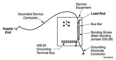
FIG. 6 grounding service conductor connection to grounding electrode. (Courtesy AVO Training Institute, Inc.)
Grounding Electrode System
A grounding electrode system is made up of a grounding electrode(s), any required bonding jumpers between electrodes, and a grounding electrode conductor. All conductors and jumpers used in the grounding electrode system must be sized in accordance with nec section 250.66 and connected as specified in section 250.70. Several types of grounding electrodes may be available at each building or structure. All available electrodes must be bonded together and used to form a grounding electrode system. Available electrodes include metal underground water pipe, the metal frame of a building, concrete-encased electrodes, and ground rings.
FIG. 8 illustrates several common types of grounding electrodes. Several of the electrodes mentioned above have specific requirements as noted in FIG. 9.
FIG. 7 location of the main bonding jumper. (Courtesy AVO Training Institute, Inc.)
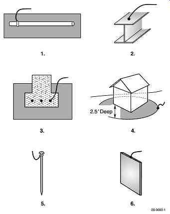
FIG. 8 Types of grounding electrodes. (Courtesy AVO Training Institute,
Inc.)
If only a water pipe is available for the grounding electrode, it must be supplemented by one of the other electrodes mentioned above or by a made electrode as illustrated in FIG. 10.
Made electrodes, such as a ground rod, pipe, or plate, may also be utilized to supplement existing electrodes. FIG. 11 illustrates the minimum requirements for a ground rod or pipe.
Two alternate installation methods for ground rods or pipes are permitted to be utilized if vertical installation is not possible due to rock or other obstructions. FIG. 12 illustrates these alternate methods.
FIG. 13 illustrates the minimum requirements for a ground plate.
Where practicable, these made electrodes are required to be installed below the permanent moisture level and be free from nonconductive coatings. If more than one electrode is used, they must be installed at least 6 ft from each other. A common practice is to place the rods apart at a distance equal to the length of the rod. The best industry practice is to install the rods at least 10 ft apart. This practice will minimize the risk of dissipation overlap in the event of a ground fault.
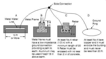
---- FIG. 9 Electrode connections. (Courtesy AVO Training Institute,
Inc.)
Metal frame must have a low-impedance ground connection providing a path to earth. Aluminum may be used if kept 18 in above earth.
At least No.4 rebar (1/2 in) with a minimum length of 20 ft Rebar must be encased with no less than 2 in of concrete.
At least No.4 bare copper and it must encircle the building and must never be less than 20 ft.
Metal Water Line 10 ft or More Ground Ring Rebar Metal Frame 18 in 2 in Sole Connection A B C D
-------
Water Line Connection must be made within 5 ft of the entrance of the building.
Water Line Sole Connection Sole Connection Supplemental Electrode Supplemental Electrode
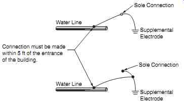
FIG. 10 Sole connections. (Courtesy AVO Training Institute, Inc.)
-----
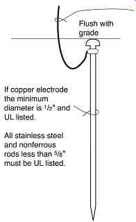
FIG. 11 Minimum requirements for a ground rod or pipe. (Courtesy AVO
Training Institute, Inc.)
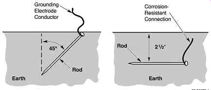
FIG. 12 Alternate burial methods for ground rods. (Courtesy AVO Training
Institute, Inc.)
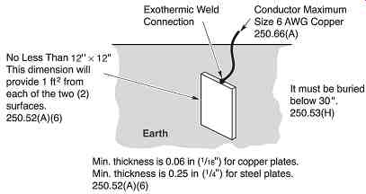
FIG. 13 Plate electrode minimum requirements. (Courtesy AVO Training
Institute, Inc.)
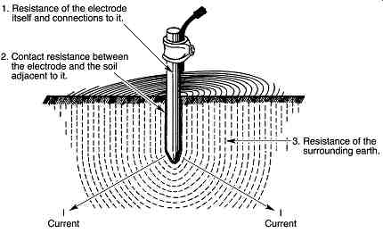
FIG. 14 Components of earth resistance in an earth electrode. (Courtesy
AVO Training Institute, Inc.)
Grounding Electrode System resistance
Resistance of all grounding connections must also be addressed briefly. There are three components of resistance to consider: (1) grounding electrode resistance, (2) contact resistance between the electrode and the soil, and (3) the resistance of the soil. These three components are illustrated in FIG. 14.
The grounding electrode, as a general rule, has very low resistance. The contact of the electrode with the surrounding soil is also generally low. The third component, soil, can very dramatically in resistance from one location to another due to different types and conditions of the soil. For example, the resistivity of inorganic clay can range from 1000 to 5500 ohm/cm whereas gravel can range from 60,000 to 100,000 ohm/cm.
Every type and condition of soil will, as can be seen, vary tremendously. The soil type must be known and grounding electrode testing must be done periodically to know whether or not a good grounding system is present. NEC Section 250.53(A)(2) Exception states that if the resistance of a single rod, pipe, or plate electrode is 25 ohm or less, a supplemental electrode is not required. This exception indicates that if the electrode resistance is greater than 25 ohm, an additional electrode(s) would be required to obtain a resistance of 25 ohm or less. As was mentioned earlier, make sure the electrodes are spaced far enough apart to prevent dissipation overlap.
Grounding Electrode conductor
OSHA 29 CFR 1910.399 defines the grounding electrode conductor as: "The conductor used to connect the grounding electrode to the equipment grounding conductor, to the grounded conductor, or both, of the circuit at the service equipment or at the source of a separately derived system." although copper is the preferred material for the grounding electrode conductor, aluminum and copper-clad aluminum are also acceptable. There are, however, restrictions with the latter two materials. The aluminum and copper-clad aluminum conductors are not allowed by code to be installed in direct contact with masonry or the earth, or where corrosive conditions exist. If used, these materials must not be installed within 18 in of earth.
Copper, on the other hand, is considered a corrosion-resistant material and, therefore, is permitted to be installed in most locations.
NEC Section 250.64(C) requires the grounding electrode conductor to be installed in one continuous length without splice or joint. There are, however, two deviations from this rule.
A splice can be made using a listed irreversible compression-type connector or the exothermic welding process. More on this subject will be addressed in the next section, "Grounding Conductor Connection to electrode. The grounding electrode conductor must be sized by the requirements of NeC Section 250.66. The conductor is sized based on the size of the largest service-entrance conductor or equivalent area of parallel conductors. The size can also vary according to the type of connection used, as will be discussed in the next section. Other deviations to the values presented in NEC table 250.66 are as follows:
1. Connections to made electrodes. The sole connection portion of the conductor is not required to be larger than No. 6 copper wire.
2. Connections to concrete-encased electrodes. The sole connection portion of the conductor is not required to be larger than No. 4 copper wire.
3. Connections to ground rings. The sole connection portion of the conductor is not required to be larger than the conductor used for the ground ring. NeC Section 250.52(a) (4) states "not smaller than No. 2" copper wire.
Grounding Conductor Connection to Electrodes
NeC Section 250.68(B) states that the connection of the grounding electrode conductor must be made in a manner that will ensure a permanent and effective grounding path.
Section 250.70 provides the means of connection of the grounding electrode conductor to the grounding electrode. These methods include exothermic welding, listed lugs, listed pressure connectors, listed clamps, and other listed means of connection. Note the term "listed" for various connection methods. These are designed, manufactured, listed, and labeled for the purpose and are the only ones permitted for use in grounding electrode systems. The code goes on to state that connections made with solder must not be used.
Solder has a very low melting point and, therefore, would disconnect the grounding connection in the event of a ground fault because the solder would act like a fuse. The National electrical Safety Code (NeSC) states that joints in grounding conductors must be made and maintained so as not to materially increase the resistance of the grounding conductor. The NeSC also states that the connection must have appropriate mechanical and corrosion resistant characteristics.
Ieee Std. 80, "Guide for Safety in AC Substation Grounding," is an excellent resource for determining the minimum size conductor based on the type of connection used. The Onderdonk AC equation is used to calculate fusing current of a conductor based on the type of connection used. Connectors and splice connections must also meet the requirements of Ieee Std. 837 to be acceptable. The following examples will further illustrate this point:
For this example, a shortened version of the Onderdonk equation will be used to determine conductor size and to determine fusing current levels based on the type of connection.
As can be seen by the previous examples, if a pressure-type connection were used, it would require a conductor approximately 60 percent larger than a connection made with a welded or irreversible compression-type connection. The brazed connection would require a conductor approximately 31 percent larger than a welded or irreversible compression-type connection. For practical purposes, the welded or irreversible compression-type connection would be the preferred choice.
Another consideration would be the approximate fusing current of the conductor based on the type of connection. This example will use a 4/0 (211,600 circular mils) conductor with a protective device clearing time of 5 cycles (0.083 second) using I A K S = / .
1. Pressure-type connection:
I = 105,528 amperes fusing current As can be seen in the above examples, the conductor utilizing the welded or irreversible compression-type connection will handle much more current before fusing than the pressure type connection.
When reliability and cost are taken into consideration, it is plain to see that the welded and the irreversible compression-type connections are far superior to any other type of connection.
Bonding
If only one statement were to be made about grounding and bonding, it would be that all non-current-carrying parts of electrical equipment and nonelectrical equipment, likely to become energized, should be effectively grounded and bonded together. By using this general philosophy, there will be a minimum (near zero) risk that the non-current-carrying parts of equipment could become energized. This would greatly reduce the risk of electrical shock or electrocution of any person likely to come into contact with the equipment. As discussed earlier, a general statement in OSHA 29 CFR 1910.303(b)(1)(vii) includes, "other factors which contribute to the practical safeguarding of persons using or likely to come in contact with the equipment." One of these "other factors" refers to grounding and bonding of equipment likely to become energized.
NEC Section 250.90 states that bonding must be provided where necessary to ensure electrical continuity. Bonding is also required to ensure the capacity to safely conduct any fault current that is likely to be imposed on the equipment. This requirement applies to all types of equipment, systems, and structures. NEC Article 250, Part v. Bonding, must be complied with to size the bonding jumper correctly. Table 2 illustrates further why Part v must be adhered to.
The key here is to know where the bonding jumper is and what it is being used for; it makes a significant difference. If the wrong section or table is used, the bonding jumper may not be of adequate current-carrying capacity to safely conduct any fault current likely to be imposed on it.
=====
Table 2 Reference Table for Sizing Bonding Jumpers
Paragraph Reference for sizing Supply side of service Table 250.66 load side of service Table 250.122 Interior water pipe Table 250.66 Multiple occupancies Table 250.122 Multiple buildings-common service Section 250.122 Separately derived systems Table 250.66 Other metal piping Table 250.122 Structural steel Table 250.66
=====
Equipment Grounding
Equipment to Be Grounded
Equipment to be grounded essentially means that all non-current-carrying metal parts of electrical equipment, whether fastened in place or portable, must be grounded. NEC Article 250, Part vI, "Equipment Grounding and Equipment Grounding Conductors," very specifically lays out the requirements for equipment grounding for electrical as well as non electrical equipment that could become energized. NEC Section 250.110 lists the requirements for equipment fastened in place (fixed) and has three exceptions. Exception No. 2 itemizes, "distribution apparatus, such as transformer and capacitor cases, mounted on wooden poles, at a height exceeding 8 ft above the ground or grade level." This exception would protect the general public from possible contact with the ungrounded apparatus; however, it does not protect the person working on the pole. With regard to these issues, OSHA 29 CFR 1910.269(l)(9) states:
Non-current-carrying metal parts. Non-current-carrying metal parts of equipment or devices, such as transformer cases and circuit breaker housings, shall be treated as energized at the highest voltage to which they are exposed, unless the employer inspects the installation and determines that these parts are grounded before work is performed.
The best practice is to always ground every case or enclosure that contains electrical equipment or conductors. When in doubt, ground it.
Grounding cord- and plug-connected Equipment
NEC Section 250.114 states the same philosophy for cord- and plug-connected equipment, as does Sections 250.110 through 250.112 for fixed equipment. It directs that all exposed non-current-carrying metal parts that are likely to become energized must be grounded. A key point here is "likely to become energized." Any metal housing or enclosure that contains electrical components is, at some time or another, likely to become energized. Proper equipment grounding techniques will provide the sufficiently low-impedance path required to cause the overcurrent device to operate and clear the ground-fault condition.
In the material written about electrical safety-related work practices, OSHA has pro vided specific requirements for the use of portable electrical equipment and extension cords. This requirement is found in OSHA 29 CFR 1910.334 where it states:
Use of equipment. (a) Portable electric equipment. (3) Grounding type equipment. (i) A flexible cord used with grounding type equipment shall contain an equipment grounding conductor.
(ii) Attachment plugs and receptacles may not be connected or altered in a manner which would prevent proper continuity of the equipment grounding conductor at the point where plugs are attached to receptacles. Additionally, these devices may not be altered to allow the grounding pole of a plug to be inserted into slots intended for connection to the current-carrying conductors.
(iii) Adapters which interrupt the continuity of the equipment grounding connection may not be used.
OSHA makes it very clear that this type of equipment must be grounded. Note as well the statement in (iii) concerning adapters. The adapters referred to here are used when a grounded plug is required to be used where an ungrounded receptacle exists. These adapters are UL approved and can be used, but only if used properly; that is, the ground connection must be attached to a return ground path. The problem with adapters is that the ground connection device is generally cut off or otherwise not used, thus defeating the ground continuity.
Equipment grounding conductors are required as stated previously; however, grounding alone does not give complete protection when using portable cord- and plug-connected, hand-held equipment and extension cords. The use of a ground-fault circuit interrupter (GFCI) when using portable equipment will provide additional safety for the user.
Grounding does provide a path for ground-fault current to flow to cause the overcurrent device to operate; however, it does not provide protection when current leakage occurs due to moisture in a piece of equipment or when there is an undetected cut in the cord or crack in the equipment case. The GFCI is designed to trip at 4 to 6 mA of current. To explain this further, the following example is provided.
Given a 20-ampere rated molded case circuit breaker, the maximum load allowed by code is 16 amperes (80 percent of rating). At 16 amperes, this circuit breaker will, under normal conditions, run indefinitely. Even at 20 amperes, the circuit breaker will remain closed for several minutes to infinity. Taking this into consideration, the amount of current leakage from moisture in the equipment (a hand-held drill, for example) will not trip this circuit breaker; however, a solid ground fault will. Since the circuit breaker will not trip, a person contacting this piece of equipment is exposed to a shock or electrocution hazard. It takes approximately one-tenth of an ampere to cause ventricular fibrillation in most people, which is generally fatal. The point is that the circuit breaker will not protect a person in this situation but a GFCI will.
NEC Section 590.6 requires ground-fault protection for all temporary wiring installations for construction, remodeling, maintenance, repair, demolition of buildings, structures, equipment, or similar activities. In other words, any time an extension cord is used for one of these activities, a GFCI is required. Although not specifically required here, and because the hazard risk is the same, all hand-held cord- and plug-connected portable electrical equipment should utilize a GFCI for the protection of the worker.
FIG. 15 further illustrates how a GFCI works.
Use a GFCI; it may save your life. Look at it this way-it is cheap life insurance.
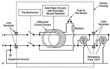
FIG. 15 Internal diagram of a ground-fault circuit interrupter (GFCI).
(Courtesy AVO Training Institute, Inc.)
Equipment Grounding conductors
NEC Section 250.118 identifies several types of equipment grounding conductors. These types vary from an equipment grounding conductor run with circuit conductors or enclosing them. It can consist of one or more of the following:
1. A copper, aluminum, or copper-clad aluminum conductor
2. Rigid metal conduit
3. Intermediate metal conduit
4. Electrical metallic tubing
5. Flexible metal conduit and fittings listed for grounding
6. liquid-tight flexible metal conduit and fittings listed for grounding
7. Flexible metallic tubing, under conditions
8. Type AC armored cable
9. Copper sheath of type MI cable
10. Type MC cable metal sheath
11. Cable trays meeting the requirements of NEC Section 392.3(C) and 392.7
12. Cable bus framework permitted by NEC Section 370.3
13. Other metal raceways listed for grounding that are electrically continuous
14. Surface metal raceways listed for grounding
The equipment grounding conductor can either be bare, covered, or insulated. When the conductor is insulated, it must be identified by a continuous outer finish of green, or green with one or more yellow stripes, or it must be bare. Equipment grounding conductors larger than No. 6 and multiconductor cable, where one or more conductors are designated for use as an equipment grounding conductor, must be permanently identified as the equipment grounding conductor by green striping, coloring, or taping.
Sizing Equipment Grounding conductors
Equipment grounding conductors are required to be sized not smaller than is stated in NEC Table 250.122 and are not required to be larger than the supply conductors. Section 250.122(B) states that if conductors are adjusted in size to compensate for voltage drop, the equipment grounding conductor must be adjusted proportionately according to circular mil area. The following example further illustrates this:
A circuit utilizing a No. 1 THW copper conductor that is protected by a 100-ampere circuit breaker would use a No. 8 copper equipment grounding conductor (according to NEC Table 250.122). Due to voltage drop, the ungrounded conductor size must be increased to a 1/0 conductor. To now adjust the size of the equipment grounding conductor proportionately by circular mil area, the following calculation must take place (values of circular mil area are found in NEC Table 8):
Given
No. 1 conductor = 83,690 circular mil area No. 8 conductor = 16,510 circular mil area 1/0 conductor = 105,600 circular mil area
No._1 ungrounded conductor No._8 grounded conductor No._1/0 unground
This calculation determines that the minimum size of equipment grounding conductor requires a 20,828 circular mil area. Referring again to NEC Table 8, it is noted that this does not correspond to a standard size conductor; therefore, the next larger conductor must be used. In this case, a No. 6 copper conductor must be used, which has a 26,240 circular mil area. This is what the NEC refers to when it says "adjusted proportionately according to circular mil area." There is an important note just below NEC Table 250.122 that is very often overlooked.
It states, "Where necessary to comply with Section 250.4(A)(5) or (B)(4), the equipment grounding conductor shall be sized larger than this table." Section 250.4(A)(5) states that grounding conductors "shall be capable of safely carrying the maximum ground-fault cur rent likely to be imposed on it." Too many times, equipment grounding conductors are sized according to Table 250.122 without considering these other facts. In this case, the conductor may not be able to safely carry the fault current. As was seen earlier, at a given value of current, the conductor will fuse (melt), the ground is now lost, and the equipment case or enclosure would become energized, which would create a shock or electrocution hazard.
Use of Grounded circuit conductor for Grounding Equipment
NEC Section 250.24(A)(5) states that the grounded conductor (current-carrying neutral) and the grounding conductor (non-current-carrying) shall not be connected together on the load side of the service disconnecting means (see FIG. 16). FIG. 17 further illustrates this point.
FIG. 16 Neutral and ground to be separated on load side of service. (Courtesy AVO Training Institute, Inc.)
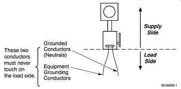
FIG. 17 Grounding requirements at the service (supply side). (Courtesy
AVO Training Institute, Inc.)
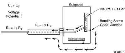
FIG. 18 Ground loop. (Courtesy AVO Training Institute, Inc.) Subpanel
The hazard of making this connection on the load side is that a parallel return path has now been established. The metallic raceway becomes a parallel return path with the grounded conductor. The metallic raceway will generally have higher impedance than the grounding conductor. As a result, the I × R values will be different in the parallel return paths. A different voltage rise will occur and thus a difference in potential will exist between the grounded conductor and the metallic raceway. A difference in potential may result in a shock hazard for anyone coming into contact with the metallic raceway. See FIG. 18 for more on this issue.
Another issue that must be addressed is proper grounding for two or more buildings where a common service is used. This issue deals with the grounding electrode, grounded (neutral) conductor, equipment grounding conductor, and bonding. NEC Section 250.50 requires the grounding electrodes at each building to be bonded together to form the grounding electrode system. Where no grounding electrode exists, one must be installed.
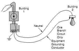
FIG. 19 One branch circuit with equipment grounding conductor run,
no electrode is required. (Courtesy AVO Training Institute, Inc.)
There are, however, exceptions to this rule. Where the second building has only one branch circuit and an equipment grounding conductor is installed with the supply conductors, the grounding electrode at the main building is all that is required. FIG. 19 illustrates this in simple form.
Section 250.32(B)(1) requires an equipment grounding conductor to be run to the separate building where there is equipment that is required to be grounded. In this case, the grounding and grounded conductors are prohibited from being connected together. The grounded conductor is considered to "float' in this case because it is not bonded to the equipment enclosure and grounding conductor. See FIG. 20 for further information on this.
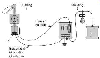
FIG. 20 Equipment grounding conductor run to second building. (Courtesy
AVO Training Institute, Inc.)
Section 250.32(B)(1), Exception states another situation that can be used. Where the installation was in compliance with a previous code, and where there is no equipment grounding conductor run with the supply conductors, the buildings are not bonded together through metal raceways or other piping, and there is no ground-fault equipment installed at the common service, the grounded conductor from the main building must be connected to the grounding electrode and bonded to the disconnecting means at the second building. This type of situation is essentially the same as that for individual services at each building. FIG. 21 illustrates this further.
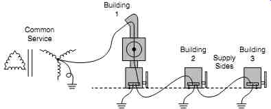
FIG. 21 Common service with no equipment grounding conductor run. (Courtesy
AVO Training Institute, Inc.)
Ferroresonance
Another very important safety issue associated with proper system grounding is ferroresonance. Ferroresonance is a rare phenomenon in power systems, but one that deserves mention. In response to a voltage transient, phase to ground fault, circuit breaker opening, equipment energization or de-energization, lightning-induced overvoltages, or any number of other sudden changes, the power system can take a sudden nonlinear jump to a sustained condition of severe harmonic distortion and high (several per-unit) overvoltages that can severely damage power system equipment. Ferroresonance is an electrical resonance between the nonlinear inductance of a transformer and system capacitance. Effective grounding decreases the chances of ferroresonance in three ways:
• Placing a very low impedance in parallel with the system capacitance.
• Fixing the electrical neutral of the system. Ferroresonance seems to require one point in the system whose potential is not fixed, like the floating neutral of an ungrounded system.
• Controlling and limiting system overvoltages that can initiate a ferroresonance.
For more information, consult any power system analysis text. An excellent reference is a technical paper by Jefferson Bronfeld, P.E., titled Ferroresonance. It is available at cadickcorp.com. Another excellent reference by Philippe Ferracci is also titled Ferroresonance and can be found at schneider-electric.com
Summary
Proper grounding is an essential part of electrical safety. Without proper grounding, the non-current-carrying metal components of electrical equipment have the risk of becoming energized. Design and install a grounding system based on the requirements of the National Electrical Code, the IEEE Std. 142 (Green Book), and IEEE Std. 80, as well as any other national standards that are relevant to the application.
FIG. 22 provides an overall look at electrical system grounding requirements based on the current edition of the National Electrical Code.
Note: Don't take a shortcut with grounding; it may cost someone his or her life. That someone might be you.
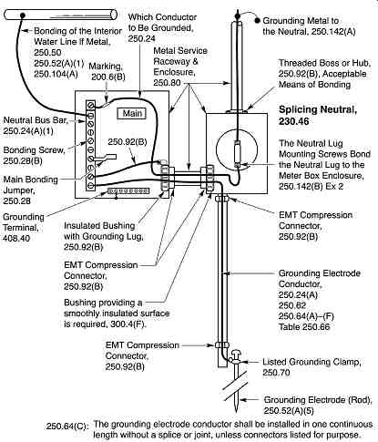
FIG. 22 Service grounding and bonding requirements. (Courtesy AVO Training
Institute, Inc.)
| Top of Page | PREV: part 1 | NEXT: Electrical Maintenance and Its Relationship to Safety | Index |