AMAZON multi-meters discounts AMAZON oscilloscope discounts

One of the most important sections in any piece of electronic equipment is the power supply. It is the part that furnishes the operating voltages and currents required by the rest of the circuitry. If the power supply is not operating correctly, the equipment cannot do the job it is supposed to do.
You have already studied the basic components used in power supplies. In this lesson, you will learn more about these parts and how they are used together in power supplies. You will be introduced to some new circuits and will learn the purpose of each part in the power supply. Once you know how the various parts are used and understand what each is supposed to do, you will be able to service any power supply defect you encounter.
A power supply may or may not have a power transformer. A power transformer is a convenient device that can be used either to increase or decrease the line voltage to the value needed by the equipment. In addition, a power transformer isolates the equipment from the power line, making the equipment safer to operate and repair. You will begin this lesson by learning about transformers.
After you have studied transformers, you will study the different rectifiers used in modern power supplies. The power supplied by utility companies for home and industrial use is ac power, whereas the transistors and integrated circuits used in electronic equipment require dc operating voltages. The device that changes the current from ac to dc is called a rectifier.
Once the ac is changed to dc, we have what is called a pulsating dc at the output of the rectifier. This is actually dc with ac superimposed on it. The power supply must therefore have some means of filtering or smoothing the pulsating dc to get pure dc. This is accomplished by means of a filter network, which separates the ac and dc components of the pulsating de at the rectifier output so that only the dc appears at the output of the filter network.
Many power supplies have some type of voltage-divider network. Such a network is designed to provide several different operating voltages from one power supply. The various transistors and integrated circuits in a piece of electronic equipment may require several different operating voltages. It is more economical in most cases to use a single power supply and a voltage divider instead of a separate power supply for each voltage needed.
Often, if an electronic circuit is to work correctly, the voltage applied to it must be very carefully regulated. You've already seen how a zener diode and forward-biased diode can be used for voltage regulation. These options are satisfactory where only small amounts of power are needed. In higher current applications, more elaborate voltage regulators are needed. Your study of power supplies will include voltage regulator circuits.
TRANSFORMERS
Our modern industrial society consumes large amounts of electricity. The transformer contributes greatly in the economical transmission of this power. We'll describe this later, but first let's learn more about transformers.
Basic Transformer Action
Transformers are particularly useful because they can increase or decrease the available voltage. For example, a transformer can be plugged into a power line that has a nominal voltage of 120 volts, and it can step that voltage down to any value we may require, providing the transformer has the correct turns ratio.
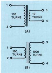
Figure 1. (A) A step-down transformer with 100 turns on the primary
winding and 10 turns on the secondary. (B) A step-up transformer with
100 turns on the primary and 1000 turns on the secondary.
In Fig.1, we've shown the schematic symbol for two transformers. The transformer in Fig.1(A) has 100 turns on the winding connected between terminals 1 and 2 and 10 turns on the winding between terminals 3 and 4.
The transformer shown at (B) also has 100 turns on the winding between terminals 1 and 2, but it has 1000 turns on the winding connected between terminals 3 and 4.
If we apply 100 volts ac to terminals 1 and 2 of the transformer shown at (A), assuming no losses in the transformer, the voltage between terminals 3 and 4 will be 10 volts. Notice that in this transformer we have 100 turns on the winding between terminals 1 and 2, which is called the primary winding, and 10 turns on the winding between terminals 3 and 4, which is called the secondary winding.
The turns ratio is 100 to 10 or simply 10 to 1. Notice that applying 100 volts to the primary winding produces 10 volts in the secondary. Notice also that the ratio of the primary voltage to the secondary voltage is the same as the ratio of the primary turns to the secondary turns. Since the voltage is stepped down, that is, it is lower in the secondary than it is in the primary, we call the transformer at (A) a step-down transformer.
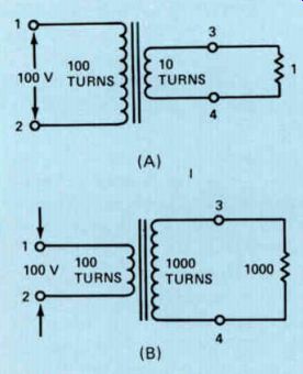
Figure 2. The transformers of Fig .1 with (A) a 1 ohm load across the
secondary and (B) a 1000 ohm load.
Now if we apply 100 volts ac to the primary winding of the transformer shown in Fig.1(B), we'll get 1000 volts between terminals 3 and 4. Once again, remember that we said the primary winding has 100 turns and the secondary has 1000 turns. Here we have a primary-to-secondary ratio of 100 to 1000, which is 1 to 10. The ratio between the voltage in the primary and the voltage in the secondary will be the same as the turns ratio; therefore, we'll have 10 times as much voltage across the secondary as we have across the primary.
Thus, if we apply 100 volts to the primary winding, we'll have 1000 volts across the secondary winding. Because it steps up the voltage, we call it a step-up transformer.
Transformers are self-regulating. By this we mean that they will draw sufficient current in the primary to supply the load connected across the secondary. Looking at Fig.2(A), we have the same transformer that we had in Fig.1(A), but now we've connected a 1 ohm resistor across the secondary winding. We can find the current that will flow through the resistor by using Ohm's law.
E I = By substituting 10 volts for E and 1 ohm for R, we get: 10 = - 1 = 10 amperes
Now let's consider the power that the resistor is dissipating. We know that the voltage across the resistor is 10 volts and the current through it is 10 amps; therefore, the power must be: P=E x I= 10 x 10 = 100 watts If the resistor is dissipating 100 watts, it must be getting 100 watts from the secondary of the power transformer. This in turn has to come from the primary winding. Therefore, assuming no losses in the transformer, since the voltage across the primary is 100 volts, the current in the primary must be 1 ampere.
Notice what has happened in the step-down transformer. The voltage has been stepped down at a ratio of 10 to 1, whereas the current has been stepped up at a ratio of 1 to 10. The power consumed by the primary is exactly equal to the power the secondary is supplying to the resistor.
Now let's look at the transformer shown in Fig.2(B). The resistor connected across the secondary winding is a 1000 ohm resistor. This is the same transformer shown in Fig.1(B). The turns ratio is 1 to 10, so that with 100 volts supplied to the primary of the transformer, we know that the voltage across the secondary must be 1000 volts. If we apply 1000 volts to a 1000 ohm resistor, the current through the resistor will be 1 ampere. The power dissipated by the resistor will be equal to the voltage across it times the current through it, so in this case it is equal to 1000 watts. The primary winding must supply this power, and to supply 1000 watts, it will have to draw a current of 10 amperes. Thus, we have 1000 watts consumed by the 100 volt power line and inductively coupled to the secondary. The secondary is supplying the 1000 watts dissipated by the 1000 ohm resistor.
Notice that in the step-up transformer we have the voltage stepped up at a ratio of 1 to 10 and the current stepped down at a ratio of 10 to 1.
Notice that in each case the current did the opposite of what the voltage did. If the voltage is stepped up, the current is stepped down; and if the voltage is stepped down, the current is stepped up. This occurs because the transformer is self-regulating. Thus, if the secondary is supplying the power at a lower voltage than that applied to the primary, the primary current will be lower than the secondary current. On the other hand, if the secondary is supplying the power at a higher voltage than the primary, then the primary current will be greater than the secondary current.
Transformers frequently have more than one secondary winding. One winding might be a step-down winding, where the voltage is lower than that applied to the primary, while the other might be a step-up winding, where the voltage will be higher than that applied to the primary. An example of such a transformer is shown in Fig.3.
In the transformer shown in Fig.3, we have 100 turns on the primary winding connected between terminals 1 and 2. We are going to apply a voltage of 100 volts between these two terminals. The secondary winding connected between terminals 3 and 4 has 10 turns on it, and we are going to connect a 1 ohm resistor between terminals 3 and 4. The secondary winding connected between terminals 5 and 6 has 1000 turns on it, and we are going to connect a 1000 ohm resistor across it.
As before, the turns ratio between the primary winding and the secondary winding connected between terminals 3 and 4 is 10 to 1. The voltage will be stepped down from 100 volts to 10 volts, and 10 volts across a 1 ohm resistor will cause a current of 10 amperes to flow. The power supplied to the resistor by the winding connected between terminals 3 and 4 will be equal to 100 watts.
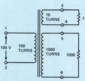
Figure 3. A transformer with a secondary step-down winding and a secondary
step-up winding.
The winding connected between terminals 5 and 6 has 10 times as many turns as the primary, so the voltage will be stepped up from 100 volts to 1000 volts. With a 1000 ohm resistor connected between terminals 5 and 6, the current through the resistor will be 1 ampere. The power supplied by this winding will then be 1000 x 1 = 1000 watts. Thus, the two secondary windings together are supplying a power of 1100 watts. This power must be taken from the power line by the primary winding.
To supply 1100 watts to the secondary windings, the primary must draw a current of 11 amperes. Then the power consumed by the primary winding will be 1100 watts. Of this 1100 watts, 100 watts will be used to supply the 10-turn winding connected between terminals 3 and 4, with the 100 watts being supplied to the 1 ohm resistor. The remaining 1000 watts will be supplied to the 1000-turn winding connected between terminals 5 and 6 to supply 1000 watts to the 1000 ohm resistor. Notice that the transformer in Fig.3 is supplying the same amount of power to the loads as the two transformers in Fig.2.
There is no limit to the number of secondary windings that we can have on a transformer. The voltage that we'll have across a given secondary winding will depend upon the turns ratio between it and the primary winding. When several widely different operating voltages are needed, separate windings for each voltage are usually the most convenient way to get them.
Transformer Losses
In the example shown in Fig.3, we said that the primary would draw 1100 watts from the 100 volt line to supply the 1100 watts to the two secondary windings. If the transformer had no losses this would be true, but a transformer does have losses. These losses can be divided into two general groups called copper and core losses.
Copper Losses. Copper losses in a transformer occur because the wire used to wind each winding has resistance. For example, the 10-turn winding connected between terminals 3 and 4 would probably have a very low resistance because it has to supply such a high current that it would be wound with a large wire. But even if the resistance were only 1/10 of an ohm, with such a high current the loss due to the resistance of the wire could be appreciable. For example, we know that: P = I^2 R and since the current in this winding is 10 amperes, the power lost in the winding would be: P = 10 x 10 x - 1 = 10 watts 10
The current flowing through the 10-turn winding will result in a voltage drop across that winding. This means that the voltage between terminals 3 and 4 will actually be slightly less than 10 volts. In the case of 10 amperes flowing through 1/10 of an ohm resistance, we have a voltage drop of 1 volt so that the voltage applied to the 1 ohm resistor will only be 9 volts. This in turn will cause the current flowing in the circuit to fall slightly below 10 amperes, but it will still be close to 10 amperes and there will be power lost in the transformer itself. Similarly, there will be a loss in the secondary winding connected between terminals 5 and 6 due to the resistance of the wire used for the 1000-turn winding. This will also cause the actual voltage across the 1000 ohm resistor to be slightly less than 1000 volts, but the current flowing through the 1000 turns will result in power being dissipated in the transformer itself.
Thus, the primary winding not only has to supply the power being supplied by the two secondary windings, but it also has to make up for the losses in the windings. Therefore, the primary current will be slightly greater than 11 amperes. Indeed, the 100-turn primary winding also has resistance, so even more current must be drawn from the power line to make up for the loss in this winding.
All these losses mean that the transformer will draw more than 1100 watts from the power line. The transformer will draw the power it needs to supply the power delivered to the two resistors plus the power being dissipated or wasted in the transformer itself due to the resistance of the wire used for the various windings on the transformer.
All the losses in the transformer due to the resistance of the wire used in the various windings are called copper losses. Remember that the power lost in the winding is equal to: P = I^2 R The loss in the winding is equal to the current squared times the resistance of the winding.
Thus the copper losses are frequently called I squared R losses.
Core Losses. In addition to the copper losses in the transformer, there are other losses called core losses. There are three types of core losses: eddy current losses, hysteresis losses, and flux leakage losses.
If we placed the windings of a transformer on a solid core, the core itself would act like a single turn of a very large wire. A voltage would be induced in this turn causing a current to flow, which would result in losses in the core of the transformer. This type of loss is called an eddy current loss. To keep eddy current losses as low as possible, the core of a transformer is made of thin sheets of metal called laminations. The laminations are stacked as shown in Fig.4. Figure 4(A) shows what the individual laminations look like and Fig.4(B) shows how the laminations are assembled. In building the transformer, the various windings are wound on some type of nonmagnetic form and then the core is inserted in the form after the windings have been completed. With this type of construction, eddy current losses in the transformer can be kept quite low.
Another important core loss is known as hysteresis loss. If we apply a voltage to the primary winding of the transformer and cause a current to flow through the winding to magnetize the core, and then remove the voltage, the current will stop flowing but there will be some residual magnetism left in the core.
In other words, the magnetism does not drop back completely to zero. Thus on the first half cycle of ac, as the core is magnetized with one polarity and then the ac drops back to zero, the magnetism has not completely disappeared. As current begins flowing through the primary winding in the opposite direction to magnetize the core with the opposite polarity, the current has built up to some value before the magnetism has dropped to zero completely and begins to build up with the opposite polarity. This inertia in the magnetism is called hysteresis. It means that power is lost each half-cycle, bringing the magnetism back to zero before it can begin to magnetize the coil with the opposite polarity. The hysteresis loss in the core of a transformer will depend upon the type of material used in the core. Usually silicon steel is used because it has a relatively low hysteresis loss.
Another type of core loss is flux leakage loss. This loss occurs when all the turns of magnetic flux produced by the primary winding do not cut all the turns of each secondary winding on the transformer. As a matter of fact, some of the flux is lost from the core entirely. Flux leakage loss is kept at a minimum by shaping the core as shown in Fig.5.
The core itself provides a low reluctance path for the magnetic lines of force. Thus the lines of force follow the core, but some will be lost as shown in Fig.5.
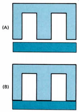
Figure 4. (A) Transformer cores are made of sheets of steel called laminations.
(B) They are put together as shown here. In the next layer, the M-shaped
lamination is turned over like a Wand put on the bottom with the straight
piece on top. Each layer is alternated in this way.
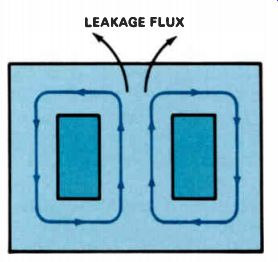
Figure 5. The transformer winding is placed on the center leg of the
core. Flux will flow around the core, but some will be lost as shown.
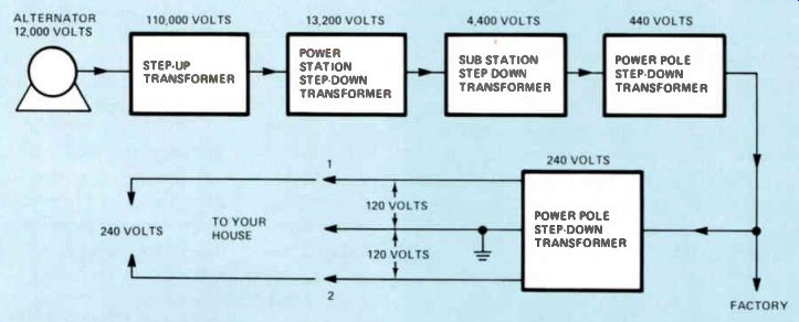
Figure 6. A typical power distribution system
Transformer Efficiency
In spite of the copper and core losses, a transformer is an extremely efficient device.
The efficiency of a transformer tells us how much of the power taken by the primary winding from the power line is actually delivered to loads connected across the secondary. If a power transformer draws 100 watts from the power line and supplies 90 watts to the loads connected across its secondary, the efficiency of the transformer is: 90
Efficiency = - 100 x 100 = 90%
Large transformers used by the power companies in the distribution of electric power are very efficient, having an efficiency as high as 98%. Smaller transformers used in electronic equipment are not as efficient, having an efficiency somewhere between 80% and 90%. The power lost in a transformer is converted into heat in the transformer. When you first turn on a piece of electrical equipment using a transformer, the transformer will be at the temperature of the surrounding air. As the transformer is used, the losses will cause the transformer to heat. It will continue to heat until a balance is reached whereby the surrounding air carries away the heat as fast as the transformer produces it. Transformers designed for use in electronic equipment usually have a maximum temperature rating of 85°C. This means that the transformer is designed so that it will not get any hotter than 85°C. It usually does not get that hot in use because before it reaches that temperature, a balance is reached where the heat being produced is being carried away by the surrounding air as fast as the transformer produces it. When this balance is reached, the transformer will not get any hotter.
Power Distribution
Earlier we mentioned that the transformer made the distribution .of large amounts of electrical power possible. You may be interested in knowing how power is generated and transmitted.
At the power generating plant, electricity is produced by large generators that are called alternators. In an alternator, the windings into which the voltage is to be induced are stationary and the rotating device is the magnet. The magnet cutting the turns of wire on the stationary coils induces a voltage in these coils. Alternators are usually designed to pro duce a voltage of about 12,000 volts. The voltage from the alternator is then fed to a step up transformer as shown in Fig.6. The transformer will step the voltage up to a very high voltage for transmission from the alternator to the main power station. The reason for stepping up the voltage to a high value is that for a given amount of power, the higher the voltage the lower the current. Since the current must flow through wires, there will be some loss in the wires. The loss depends on the current squared times the resistance of the wire. Therefore, the lower we can keep the current, the less the loss. Usually, voltages of 110,000 volts or 220,000 volts are used to transmit electricity from the power plant to the main power station. At the main power station, a second transformer is used to step the voltage down to about 13,200 volts, and it is fed from there to substations. At the sub stations, another transformer is used to step the voltage down to about 4400 volts.
The 4400 volts is then fed along high power lines to transformers mounted on poles or beneath ground. These transformers step the voltage down to 440 volts. Many factories have machines that operate on 440 volts that is fed directly to them. For the home user, another transformer is used on the power pole to step the voltage down still further. Usually the voltage fed to a residence is about 240 volts.
Three wires are used to transmit this voltage as shown in Fig.6. The voltage between terminals 1 and 2 is 240 volts, which is used in electric ranges, ovens, clothes dryers, and large air conditioners. The voltage between either terminals 1 or 2 and the center wire, which is called the neutral wire, is 120 volts. This voltage is used for lighting and for operating radio and TV receivers and other small appliances.
Notice that the neutral wire is grounded. This is done for a number of reasons, the most important of which is safety. But it also points out why it is dangerous to work on electrical equipment while standing on a damp basement floor or touching a water pipe or any other grounded object. If you happen to touch the hot line and a grounded object at the same time, you could easily be electrocuted.
Autotransformers Transformers do not have to have two separate windings. Some transformers, called autotransformers, have only a single winding. Two examples of an autotransformer are shown in Fig.7.
Notice that in Fig.7(A), there are three connections to the transformer. The input voltage is applied across the entire winding, and the output is taken off from just part of the winding. This type of autotransformer is a step-down transformer. It works in essentially the same way as a transformer with two windings in that the input voltage is applied across the entire winding and the out put is taken off only part of the winding. Thus we have, in effect, a step-down in the transformer.
In the transformer shown in Fig.7(B), the input is applied across only part of the winding. It sets up a flux that cuts the remaining turns of the winding, inducing a voltage in these turns so that the output voltage, which is taken off across the entire winding, is stepped up. The ratio of the input voltage to the output voltage in both examples will be equal to the ratio of the turns across which the input voltage is applied to the turns across which the output voltage is taken.
Autotransformers are used in some special applications. They are more economical to manufacture than transformers with two separate windings. But in power-line applications, they do not provide any isolation between the line voltage and the output voltage. So electronic equipment using an autotransformer as a power transformer is not isolated from the power line as is a conventional transformer with two separate windings.
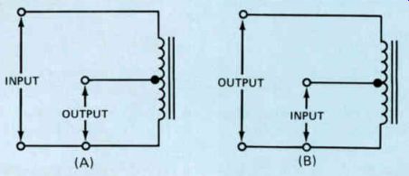
Figure 7. (A) A step-down autotransformer and (B) a step-up autotransformer.
Summary
A step-up transformer is a transformer that has more turns on the secondary winding than on the primary. The ratio of the secondary voltage to the primary voltage is equal to the ratio of the number of turns on the secondary to the number of turns on the primary. A step-down transformer has fewer turns on the secondary winding than on the primary, so the secondary voltage is lower than the primary voltage. The transformer may have more than one secondary winding; one secondary winding would have more turns than the primary to produce a voltage higher than the primary voltage, and the other would have fewer turns than the primary winding to produce a voltage lower than the primary voltage.
The transformer is very efficient, but it does have some losses. Copper losses are due to the resistance of the wire used to wind the coils on the transformer. The copper loss in each winding equals the current squared in that winding times the resistance of the winding. These are often called the I^2R losses. Core losses are made up of eddy current losses, hysteresis losses, and flux leakage losses.
The transformer core is made up of laminated stampings rather than a single piece of iron to keep the eddy current losses low. The core material is usually silicon steel, which has low hysteresis losses. Flux leakage losses are kept low by providing a complete magnetic path for the magnetic lines of flux.
Large power transformers can have an efficiency as high as 98%. Smaller transformers usually have an efficiency between 80% and 90%. The transformer is self-regulating. The power it takes from the primary power line equals the power drawn from the secondary windings plus the transformer losses.
Self-Test Questions
1 Which winding on a step-down transformer has the greater number of turns?
2 Which winding on a step-up transformer has the greater number of turns?
3 When a load is connected across the secondary winding of a step-down transformer, which winding will have the higher current?
4 When a load is connected across the secondary winding of a step-up transformer, which winding will have the higher current?
5 What is it that we mean when we say that a transformer has an efficiency of 95%?
6 What are copper losses due to?
7 Why are transformer cores made of laminations rather than a solid piece of steel?
8 Name the three core losses.
9 What is the disadvantage of an auto transformer when compared with a transformer having two separate windings?
------------------------------
RECTIFIER CIRCUITS
Any device that will pass current in one direction but not in the other direction can be used as a rectifier. Modern electronic equipment uses silicon rectifiers, which are simply silicon diodes with an n-type region for the cathode and a p-type region for the anode. Two typical silicon diodes are shown in Fig.8, along with a dime so you can get an idea of their relative size.
Silicon diodes are used as rectifiers because they are very inexpensive to manufacture and they will last indefinitely as long as the ratings of the rectifier are not exceeded. In addition, the silicon diode has a very low for ward resistance. This means that when it is passing current there will be very little power lost due to the resistance of the diode. This loss of power turns up in the form of heat, which serves no useful purpose.
In electronic equipment, you will run into half-wave rectifiers, which rectify only one half of the ac cycle, and full-wave rectifiers, which rectify both halves of the ac cycle. Let's start our study of rectifiers with the half-wave rectifier.
Half-Wave Rectifiers
We have shown a typical half-wave rectifier circuit in Fig.9(B). Figure 9(A) shows one ac cycle. This may be the ac that is coming from the power line or the secondary of a power transformer. Since current can pass through the rectifier in only one direction, the current will flow through the load in the direction shown producing the current waveform shown in Fig.9(C).
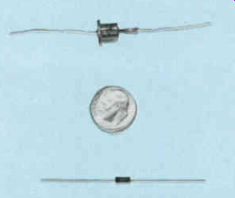
Figure 8. Two typical silicon rectifiers with a dime between them to
show their relative size
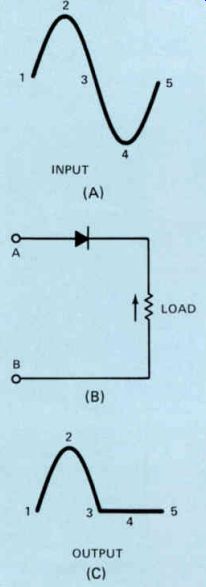
Figure 9. A half-wave rectifier
During the first half-cycle of the input voltage waveform, if terminal A is positive and terminal B is negative, electrons will flow from terminal B through the load, through the rectifier, and back to terminal A of the power source. As the input wave goes through the first half-cycle from point 1 to point 2 and then to point 3, current will flow through the load and rectifier as shown in Fig.9(C). The current will increase as the voltage applied between terminals A and B increases up to point 2 and then will decrease to point 3 as the ac input decreases. During the next half cycle, when terminal A is negative and terminal B is positive, there will be no current through the rectifier. Therefore, no current will flow through the load, as shown from point 3 to 5 in Fig.9(C). While the half-wave rectifier is a simple device, it does have the disadvantage that it takes considerable filtering to smooth its pulsating dc output to a pure dc.
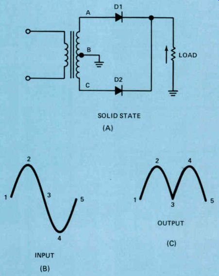
Figure 10. A Full-wave rectifier.
Full-Wave Rectifiers
A typical full-wave rectifier circuit is shown in Fig.10(A). Notice that the circuit uses two diodes, D1 and D2, and also that there are three connections to the secondary of the power transformer. Terminal B is a center tap connection, which means that the voltage between terminals A and B will be equal to the voltage between terminals B and C. When terminal A is positive, terminal B will be negative and terminal C will be even more negative. This means that terminal C will also be negative with respect to terminal B. When terminal A is positive and terminal B is negative, electrons will flow from terminal B to ground through the load and then through D1 to terminal A. Electrons will not flow through D2 to terminal C because terminal C is negative with respect to terminal B. During the next half-cycle, terminal B will be positive with respect to terminal A and terminal C will be even more positive. This means that terminal C will be positive with respect to terminal B or, in other words, terminal B is negative with respect to terminal C. During this half-cycle, electrons will flow from terminal B to ground, through the load, and then through D2 to terminal C. Electrons will not flow through D1 to terminal A
Because terminal A is negative with respect to terminal B. With an ac cycle like the one in Fig.10(B), we'll have a pulsating dc through the load as shown in Fig.10(C). Notice that for the first half-cycle of the input voltage, we get a current pulse through the load as shown by 1-2 3 in Fig.10(C). During the next half-cycle of the input voltage in Fig.10(B), we also get a current pulse as shown in 3-4-5 of Fig.10(C). In other words, for each half-cycle we get a current pulse through the load with the current flowing through D1 during the first half cycle and D2 during the next half-cycle.
Compare the output for the full-wave rectifier shown in Fig.10(C) with the output of the half-wave rectifier shown in Fig.9(C). As sliming that both rectifiers are operating from a 60 Hz power line, notice that with the half wave rectifier we get 60 pulses per second and the current is only flowing during the one half cycle. In the full-wave rectifier circuit we get 120 pulses per second, and there is current flow during each half-cycle. You can see that it will be much easier to smooth the pulsating output from a full-wave rectifier than it is to smooth the output from the half-wave rectifier.
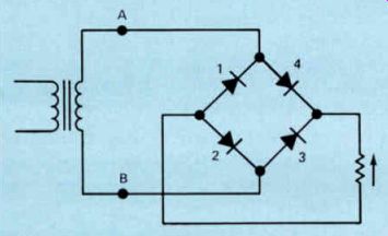
Figure 11. A bridge rectifier circuit.
Another full-wave rectifier circuit is shown in Fig.11. This is called a bridge rectifier. Since a center-tap transformer winding is not required, it has the advantage of requiring only half as many turns on the secondary winding for a given output voltage, compared to the transformer used in Fig.10. In the full-wave rectifier shown in Fig.10, we use one half of the secondary winding during one half-cycle and the other half during the other half-cycle.
Therefore, for a given output voltage, the voltage between terminals A and C of the transformer shown in Fig.10 must be twice the voltage across the secondary of the transformer shown in Fig.11. However, the circuit shown in Fig.11 does have the disadvantage that it requires four rectifiers instead of two.
But silicon rectifiers are so inexpensive that the cost of the two extra rectifiers is usually more than offset by the savings in the power transformer.
The operation of the circuit is comparatively simple. When terminal B is negative with respect to terminal A, electrons will flow from terminal B, through the diode marked 2, and then through the load and diode 4 to terminal A of the transformer. During the next half-cycle, terminal A is negative and terminal B is positive, so electrons will flow from terminal A, through diode 1, through the load, and then through diode 3 back to terminal B. Thus, during one half-cycle, current will flow through diodes 1 and 3, and during the other half-cycle, it will flow through diodes 2 and 4. Current cannot flow through diodes 2 and 4 during the half-cycle when it is flowing through diodes 1 and 3 because diodes 2 and 4 will be reverse biased. Similarly, during the next half-cycle, diodes 1 and 3 will be reverse biased and current cannot flow through them.
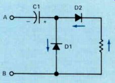
Figure 12. A half-wave voltage-doubler circuit.
Voltage Doublers
In some applications, we need a voltage higher than the voltage that is readily available. This is frequently the case in low-cost, transformerless electronic equipment. With out a power transformer, the maximum voltage available would be the 120 volt ac line voltage. But by using a voltage doubler circuit, you can obtain a higher operating voltage.
Figure 12 shows a half-wave doubler circuit. Let's see how it works. During the first half-cycle, when terminal A is negative and terminal B is positive, electrons will flow from terminal A into the side of C1 marked with a minus sign and out of the side marked with a plus sign, through D1, and back to terminal B. This will charge capacitor C1 with the polarity shown.
In the next half-cycle, when terminal A is positive and terminal B is negative, the voltage between terminals A and B will be in series with the voltage across C1. Thus, we'll have a voltage approximately equal to twice the input voltage applied across D2 and the load. During this half-cycle, current flows from terminal B, through the load and D2 into the positive side of C1, and out the negative side to terminal A. Current cannot flow through D1 because current cannot flow through the diode from the anode to the cathode.
Later, after you've studied filters, you will see that with large filter capacitors and a small load, it is possible to get a voltage equal to almost twice the peak line voltage with this type of circuit without using a power transformer.
The circuit shown in Fig.12 is called a half wave voltage doubler because current flows through the load only when terminal A is positive and terminal B is negative. In other words, we have a current flow through the load only during one half-cycle. The circuit shown in Fig.13 is a full-wave voltage doubler. Here we have a current through the load during both half-cycles.
In the circuit shown in Fig.13, when terminal B is negative and terminal A is positive, electrons will leave terminal B and flow into the negative plate of C1, out of the positive plate of C1, through D1, and back to terminal A. The capacitor C1 will be charged with the polarity shown. During the next half-cycle, when terminal A is negative and terminal B is positive, electrons will flow from terminal A through D2 into the negative plate of C2, out of the positive plate, and back to terminal B. This will charge C2 with the polarity shown. Notice that now C1 and C2 are connected in series; these two capacities supply the current through the load. Since they supply the current to the load continuously, the rectifier is a full-wave rectifier.
During the half-cycle when diode D1 is con ducting, diode D2 cannot conduct because the voltage applied to its cathode will be positive.
During the other half-cycle when D2 is conducting, D1 cannot conduct because the voltage applied to its anode will be negative. As in the case of a half-wave voltage doubler, the full-wave doubler shown in Fig.13 gives us an output voltage across C1 and C2 in series that is equal to twice the peak line input voltage. In the case of an input voltage of 120 volts ac, this would be approximately 340 volts.
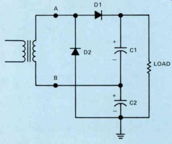
Figure 13. A full-wave voltage-doubler circuit
Summary
The rectifier circuits that we have discussed in this section of the lesson are extremely important because you will find one or more of them in every piece of electronic equipment designed to operate from an ac power line.
The half-wave rectifier circuit is important because it is widely used where the current drain is relatively low. Full wave rectifiers are used in applications where the current requirement is some what higher and where very pure dc is needed. Voltage doublers are important because they are widely used in high voltage circuits used to operate cathode ray tubes in all types of video displays.
Self-Test Questions
10 In a half-wave rectifier circuit like the one shown in Fig.9, how many current pulses per second will there be through the load when the power line frequency is 60 Hz?
11 What is the disadvantage of a half wave rectifier circuit?
12 What advantage does the bridge rectifier circuit in Fig.11 have over the full-wave rectifier in Fig.10?
13 What is the disadvantage of the bridge rectifier circuit shown in Fig.11?
14 What is the advantage of the full wave voltage doubler shown in Fig.13 over the half-wave voltage doubler shown in Fig.12?
-----------------------
FILTER CIRCUITS
The output from the rectifiers we discussed in a preceding section is not pure dc. Instead, it is pulsating dc - direct because it flows in only one direction, pulsating because it varies in amplitude rather than flowing steadily. You will remember that the half-wave rectifier shown in Fig.9 produces one pulse for each cycle. With a 60 Hz power line, there will be 60 pulses per second. Also, remember that these pulses are produced during one-half of the cycle while the output from the rectifier is zero during the other half-cycle. The full wave rectifier produces 120 pulses per second, one pulse for each half-cycle. The output from the full-wave rectifier was shown in Fig.10(C). Neither the output from the half-wave rectifier nor the output from the full-wave rectifier can be used directly to operate electronic equipment. The output from these rectifiers must be filtered until it is essentially pure dc. This is done by means of a filter circuit.
There are many different filter circuits, the simplest of them being the simple capacitor filter. We'll discuss this circuit first.
Simple Capacitor Filters
The simplest filter is the capacitor filter shown in Fig.14. When terminal A is positive and terminal B is negative, electrons will flow from terminal B to the load and through the rectifier to terminal A. They will also flow from terminal B into the negative plate of the filter capacitor C and out of the positive plate, through the rectifier to terminal A. The capacitor will charge to the peak line voltage less any small voltage drop there may be across the rectifier.
Figure 15(A) shows three ac cycles and Fig.15(B) shows what the voltage across the load in the circuit of Fig.14 will look like.
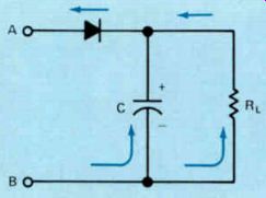
Figure 14. A half-wave rectifier circuit with a simple capacitor-type
filter.
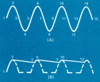
Figure 15. Voltage waveshapes for a simple filter. (A) Input voltage;
(B) output voltage.
During the first half-cycle, as the ac input voltage goes from 1 to 2, the voltage across the filter capacitor charges from 1 to 2 as shown in Fig.15(B ). As the ac line voltage begins to drop from 2 to 3, the capacitor begins to discharge. The amount it will discharge depends upon the size of the load resistor. If the resistance is high and the load draws very little current, the capacitor will not discharge a great deal. If the resistance is low and the load is drawing considerable current, the capacitor will discharge appreciably.
In any case, as the voltage begins to drop from 2 to 3, the capacitor voltage will begin to drop from 2, as shown in Fig.15(B), until the next cycle. Then, when terminal A is positive and terminal B is negative, and the voltage builds up from 5 to 6, a point will be reached where the ac input voltage is equal to the capacitor voltage. This is point 5 in Fig.15(B). Now the capacitor will begin to charge again to point 6. Once at point 6, the ac voltage begins to drop to point 7 as shown in Fig.15(A), so the capacitor begins to discharge to 9 as shown in Fig.15(B). At this point, the ac line voltage is once again built up to a value equal to the voltage to which the capacitor has discharged, so that it again charges it back to point 10.
This action continues indefinitely as long as the equipment is turned on. During each portion of the cycle when the line voltage exceeds the voltage to which the capacitor is charged, there is a burst of current through the rectifier to charge the capacitor back to the peak line voltage. Thus, with a filter circuit, the current flows through the rectifier during only a small portion of the cycle. However, it takes a fairly large current to charge the capacitor back to the peak line voltage to replace the charge that was lost.
One of the important characteristics of a rectifier is the maximum peak reverse voltage that can be placed across the rectifier be fore it breaks down. In the circuit shown in Fig.14, the capacitor will be charged as shown and the charge can equal the peak line voltage. During the next half-cycle, when the polarity of the input voltage reverses, terminal A will be negative and terminal B will be positive. When this voltage reaches its peak, the peak reverse voltage across the rectifier will be equal to the capacitor voltage plus the line voltage because the two are, in effect, in series. This voltage will be equal to twice the peak line voltage less the voltage that the capacitor has discharged. For safety, we assume the voltage is twice the peak line voltage. The rectifier must be able to withstand this voltage without breaking down. This important characteristic by which rectifiers are rated is usually referred to as the peak reverse voltage, which is abbreviated pry. It may also be called peak inverse voltage, which is abbreviated piv. The two simply mean the maximum reverse or inverse voltages that can be applied across the rectifier without breaking it down. In the circuit shown in Fig.14, operating from the 120 volt ac power line, the pry will be about 340 volts. The rating of the rectifier should be at least 400 volts pry to allow a reasonable safety factor.
You will run into this filter circuit shown in Fig.14 only in applications where the current requirements are very low. If any sizable current is drawn from this type of circuit, the capacitor will discharge appreciably and there will be 60 Hz hum in the circuit. For applications where higher current is present, additional filtering is required to eliminate this hum.
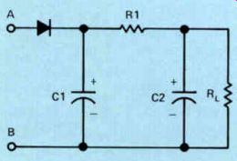
Figure 16. An RC pi-type circuit.
RC Filters
An improved filter, which is called a pi filter because it looks like the Greek letter (Pi), is shown in Fig.16. You will notice that this filter consists of two capacitors, C1 and C2, and a filter resistor, R1.
The operation of the half-wave rectifier and capacitor C1, which is called the input filter capacitor, is exactly the same as in the simple capacitor filter shown in Fig.14. The rectifier passes current to charge capacitor C1 with the polarity indicated on the diagram. The capacitor is charged by a series of pulses as shown in Fig.15. However, if the load resistance RL is low enough to draw appreciable current from the supply, the voltage across C1 will discharge appreciably during the portion of the cycle when the rectifier is not conducting. Thus, we have dc with ac super imposed on it across C. To see the action of R1 and C2, let's first consider how capacitor C2 reacts to ac and to dc. Remember that a capacitor will not pass dc. It can be charged so that dc voltage will exist across it, but applying dc to the plates of the capacitor does not cause a current to flow through it. Although electrons cannot cross the dielectric of the capacitor, applying ac to the dielectric of the capacitor produces the effect of a current flowing through it. This is because electrons will first flow into one plate and then into the other as the polarity of the ac reverses.
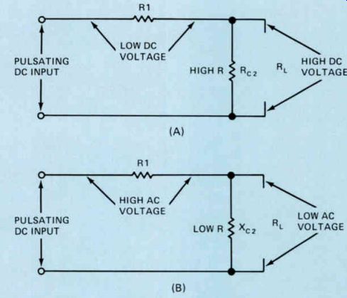
Figure 17. Equivalent circuits showing the reaction of an RC filter
(A) to dc, and (B) to ac.
You will remember from your study of capacitors that a capacitor offers what is called capacitive reactance or opposition to the flow of ac through it. The exact reactance that any capacitor will offer to the flow of ac through it is given by the formula: 1 Xc = 6.28 xfxC
You can see from this formula that the higher the capacity of the capacitor, the lower the capacitive reactance will be to an ac voltage of a particular frequency. As a matter of fact, a 50 uF capacitor, commonly used for C2 in filter circuits, has a reactance of about 50 ohms at 60 Hz.
In Fig.17(A), we have shown how the filter consisting of R1 and C2 reacts to dc; in Fig.17(B), we have shown how it reacts to ac.
As you know, a perfect capacitor would not pass any dc, but there is no such thing as a perfect capacitor because there is always a small dc current called a leakage current.
However, as far as dc is concerned, capacitor C2 acts like a very high resistance and the resistance of R1 will be whatever you have selected. In both cases, it is kept low enough so that the dc flowing through it will not cause any appreciable voltage drop.
Now look at Fig.17(B), which shows the re action of the circuit to an ac voltage. The capacitor has a very low reactance to ac, and the resistance of R1 will be much higher than the reactance of C2, so most of the ac voltage will be dropped across R1. R1 and C2 act together as a voltage divider, with most of the ac being dropped across R1 because its resistance is much higher than the reactance of C2. Consider, for example, a 50 µF capacitor which, as we mentioned before, has a reactance of about 50 ohms at 60 Hz. Suppose R1 has a resistance of 500 ohms. Its resistance is ten times the reactance of C2. Therefore, the ac voltage appearing across R1 will be ten times the ac voltage appearing across C2.
Suppose, for example, the ac voltage across C1, which is called a ripple voltage, is 20 volts.
This 20 volts will divide between R1 and C2 at the ratio of 10 to 1 so that the ripple across C2 would be less than 2 volts.
The RC filter is a much better filter than the simple capacitor filter, but it does have one disadvantage. If we make R1 too large, there will be a substantial dc voltage across the resistor. This will reduce the voltage available to the load. This problem can be overcome by the use of an LC filter.
LC Filters
The disadvantage of the resistor-capacitor type of filter shown in Fig.16 soon becomes apparent if you consider what happens because of the resistance of the filter resistor and the dc current flowing through it. If the dc current in the load is 100 mA, which is 0.1 ampere, the voltage drop across the 500 ohm filter resistor referred to in the previous section would be 50 volts. In the case of a power supply operating directly from the ac power line, a substantial portion of the available voltage would be dropped across the filter resistor. You will see this type of filter in applications where the current is reasonably low.
In applications where there is a high dc current, an LC filter like the one shown in Fig.18 is usually used.
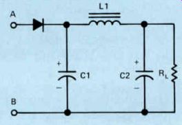
Figure 18. An LC filter.
In the LC filter, the rectifier and C1 act exactly like the simple capacitor filter shown in Fig.14. Capacitor C1, which once again is called the input filter capacitor, is charged by the input voltage and recharged by each pulse to meet the peak line voltage less the small voltage drop across the rectifier.
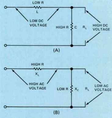
Figure 19. Equivalent circuits showing the reaction of an LC filter
(A) to dc, and (B) to ac.
The action of the filter network made up of L1 and C2 is shown in Fig.19. You already know that a capacitor has a high resistance to dc, so that the only current flow through it will be a small leakage current. Therefore, as far as the dc is concerned, the capacitor acts like a high resistance. The dc resistance of L1, which is called a choke, can be kept low by using a reasonably large wire size to wind the coil. It is comparatively easy to build a 10 henry choke with a dc resistance as low as 50 ohms. With a 50 ohm dc resistance, the voltage across the choke with a current of 100 mA would be only 5 volts. This is far less than the 50 volt drop you would get across a 500 ohm filter resistor in the circuit shown in Fig.16.
The choke coil will also offer much better filtering of the ac. A 10 henry choke has an inductive reactance of about 3750 ohms at 60 Hz. You already know that a 50 uF capacitor has a capacitive reactance of 50 ohms at 60 Hz. Therefore, as far as dividing the ac voltage is concerned, we see in Fig.19(B) that the inductive reactance of the choke, which is 3750 ohms, is in series with the 50 ohm capacitive reactance of the capacitor. We have a voltage-divider network in the ratio of approximately 75 to 1. If the ac voltage across C I is 20 volts, as in the preceding example, the voltage across the capacitor would be approximately 0.25 or about one quarter of a volt. Thus, when compared to the RC filter where we had an ac voltage division of approximately 10 to 1, with the LC filter we have an ac voltage division of approximately 75 to 1. The ac at the output of the LC filter will be much lower and the dc will be much higher.
Again, this type of filter is called a pi filter because the configuration looks like the Greek letter pi (π). C1 is called the input filter capacitor and C2 the output filter capacitor. Since the LC filter is a much better filter than the RC filter, you might wonder why we would ever use an RC filter. The answer is simply that resistors are very inexpensive, whereas the choke is not.
Factors Affecting the Output Voltage
In any filter network containing a filter choke or a filter resistor, the dc current flowing through the load must also flow through the filter choke or filter resistor. Thus there will be a voltage drop across the choke or resistor. The exact value of the voltage drop will depend upon the dc resistance and the current flowing. We've already pointed out that the voltage drop is usually lower across the filter choke than across the filter resistor for a given dc current.
If the current drawn by the load changes, the output voltage at the output of the filter network will change. You can see why this is so because the current must flow through the filter resistor or filter choke. If the current flowing through the choke or resistor were to change, the voltage drop across it would also change, and the voltage at the output of the power supply would have a tendency to change as well.
The output voltage is also affected by the size of the filter capacitors used. If the filter capacitors are too small, the rectifier won't keep them completely charged. If the capacitors are large, once the rectifier gets them charged they'll stay charged to a voltage near the peak ac voltage applied to the rectifier.
Summary In this section we have covered some of the more important types of filter net works you are likely to encounter in your career as an electronics technician. You have seen that these networks vary from comparatively simple networks consisting only of a capacitor up to networks containing a choke and two filter capacitors.
The simpler types of filter networks can be used where the current drain is low and where the filtering does not have to be perfect. More elaborate filters are used in power supplies having a high current drain and in cases where good filtering is required to supply pure de at the power supply output.
The filters in this section of the lesson are shown with half-wave rectifiers. The same filter circuits are also used with full-wave rectifiers. As a matter of fact, in applications where you want pure dc with very little ripple on the output, you almost always find a full-wave rectifier.
Self-Test Questions
15 To what value may the filter capacitor charge in the simple filter capacitor circuit shown in Fig.14?
16 In what type of application may we find a simple capacitor-type filter like the one shown in Fig.14?
17 What advantage does the RC pi-type filter shown in Fig.16 have over the single capacitor-type filter shown in Fig.14?
18 What is the advantage of an LC filter over an RC filter?
--------------------------------
TYPICAL POWER SUPPLIES
The two main sections of the power supply are the rectifier and the filter. Now that we have discussed both of these sections, let's ex amine some typical power supplies and see what they look like. First, we'll look at the universal ac-dc power supply. This type of power supply does not use a power transformer; it operates directly from the ac power line. This type of power supply is used in low cost equipment, particularly table-model radios.
Universal AC-DC Power Supplies
The universal ac-dc power supply was first developed for use in low-cost, table-model radios. You were supposed to be able to operate the radio from either an ac or dc power line.
However, when operated from dc, the maxi mum voltage to which you can charge the input filter capacitor is the dc line voltage, whereas when operated from an ac power line you can charge the capacitor to the peak value of the ac power line, which is 1.4 times the voltage obtained from a dc line. Frequently, when you tried to use one of these radios on a dc power line, it wouldn't work. But today the use of dc in power lines has all but disappeared, and although these power supplies are now intended for use on ac, the old name has stuck.
Two ac-dc power supplies are shown in Fig.20. In the circuit shown at (A), the negative terminal of the power supply is the common terminal and two positive output voltages are available. The one at C2 will be a well filtered low voltage. The output taken from across C1 will be a higher voltage, but it will not be as well filtered.
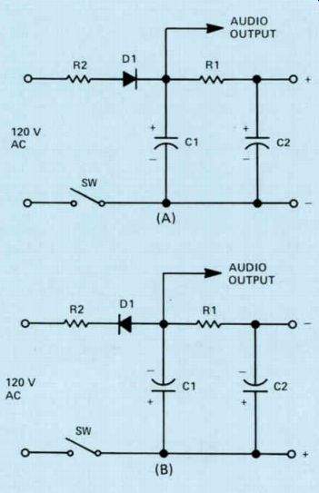
Figure 20. Universal ac-dc power supplies
In the circuit shown at (B), the diode rectifier has been reversed and this will give us the reverse polarity at the power supply out put. The positive terminal of this power supply is the common terminal and there are two negative voltages available. As before, the voltage taken across C2 is well filtered, whereas the one taken from across C1 is not.
As you can see, both these power supplies were designed for use in table-model radios.
The audio output can be taken from across C1 and this voltage is used to power the last transistor in the radio, the output transistor.
The current through a transistor depends primarily on the forward bias across the emitter base junction and not on the collector voltage.
Therefore, if there is some hum on the collector, it won't cause any appreciable change in the current through the transistor so you will not hear any hum in the output of the radio. The power supply at (A) is designed for use with a radio using NPN transistors, while the one shown at (B) is designed for use in a radio using PNP transistors.
Notice the resistor R2 connected between the diode and the power line in both supplies.
When the equipment is first turned on, C1 will be discharged. Without R2 in the circuit, the initial charging current through the diode would be so high the diode could be destroyed.
R2 limits the initial charging current to a safe value.
Although these two power supplies were designed for use in radio receivers, you will find similar power supplies in other low-cost electronic equipment. It is not always possible to take a voltage from across the input filter capacitor, but in many cases where some hum voltage does not matter and a higher voltage is needed, this is done.
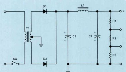
Figure 21. A full-wave power supply
Typical Full-Wave Power Supplies
A simple full-wave power supply is shown in Fig.21. Notice that this power supply uses a power transformer and that the secondary of the transformer is tapped and the tap is grounded. During one half-cycle, D1 will con duct and during the other half-cycle D2 will conduct.
Notice that we have resistors R1, R2, and R3 across the output. These resistors will make it possible for us to get three different operating voltages from the power supply. The resistors are also connected across the output of the power supply to serve another purpose.
They will discharge the capacitors C1 and C2 when the equipment is turned off. Usually the filter capacitors will have a fairly high capacity, so it is desirable to discharge them when the equipment is turned off to prevent an accidental shock.
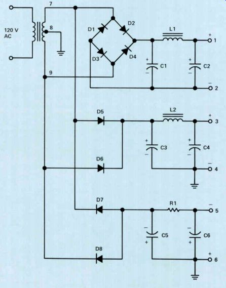
Figure 22. A multiple output voltage power supply.
A power supply designed to produce multiple output voltages is shown in Fig.22. At first this might look like a complicated supply, but actually it is made up of three simple supplies operating from a single transformer.
To see how it works, first look at the circuit made up of diodes D1, D2, D3, and D4. Notice that terminal 7 of the transformer connects to the junction of D1 and D2 and terminal 9 connects to the junction of D3 and D4. When terminal 7 is positive with respect to terminal 9, electrons will flow from terminal 9 to the junction of D3 and D4 and then through D3 to the minus terminal, which is terminal 2.
From there they will flow through the load to terminal 1, through the choke and D2 to terminal 7 of the transformer. During the next half-cycle, when terminal 7 is negative and terminal 9 is positive, electrons will flow from terminal 7 through D1 and then to terminal 2 of the power supply output, through the load to terminal 1, through L1, and then through D4 to terminal 9 of the transformer. You can see we have a bridge rectifier circuit rectifying the full voltage between terminals 7 and 9. The pi-section LC filter consisting of C1, L1, and C2 filters the output from the rectifiers and changes the pulsating dc to smooth dc.
Now notice that terminal 7 of the transformer connects to D5 and terminal 9 connects to D6. Terminal 8 of the transformer is grounded. When terminal 8 is negative with respect to terminal 7, electrons will flow from terminal 8 to ground, to terminal 4 at the output of the power supply, through the load to terminal 3, and then through L2 and D5 back to terminal 7. During the next half-cycle, when terminal 8 is negative with respect to terminal 9, electrons will flow from terminal 8 to ground and then to terminal 4, through the load to terminal 3, through L2, and through D6 to terminal 9 of the transformer. Here we have a full-wave power supply using the center tap of the transformer and producing a voltage between terminals 3 and 4 such that terminal 3 is positive with respect to terminal 4. C3, L2, and C4 form a pi-section LC filter network.
Now let's see what happens in the power supply made up of D7 and D8. When terminal 7 is negative with respect to terminal 8, electrons will flow from terminal 7 to D7, through the diode, and then through R1 to the negative terminal (terminal 5), through the load back to terminal 6, and from there to ground and over to terminal 8. During the next half cycle, when terminal 9 is negative with respect to terminal 8, electrons will flow from terminal 9 through D8, through R1 to terminal 5, through the load to terminal 6, from terminal 6 to ground, and back to terminal 8. Now we have a power supply where terminal 5 is negative with respect to terminal 6. Thus we have a negative voltage available between ground and terminal 5. The RC filter consisting of C5, R1, and C6 smooths the pulsating output from rectifiers D7 and D8 to smooth dc.
Thus, from the one transformer we have three separate output voltages. We have a high voltage between terminals 1 and 2, a positive voltage that is about half as high between terminals 3 and 4, and a negative voltage at terminal 5 that would be approximately equal to the positive voltage on terminal 3.
Summary
Most modern electronic equipment you will encounter will use full-wave power supplies with either a rectifier circuit like the one shown in Fig.21 or a bridge rectifier. Bridge rectifiers are widely used because the savings in the cost of the transformer more than offsets the cost of the two extra rectifiers. While half-wave rectifiers are not as common, they are useful in some applications.
Modern power supplies use a pi-type filter network. The filter network may be either an RC network or an LC net work. LC networks usually provide better filtering and better voltage regulation.
Self-Test Questions
19 Why are the filter capacitors in Fig.20(B) connected with the opposite polarity to those in Fig. 20(A)?
20 What is the disadvantage of the full wave power supply shown in Fig.21 compared to a bridge rectifier?
21 Between which two output terminals of the power supply shown in Fig.22 is the highest output voltage available?
In the bridge rectifier circuit in Fig.22, when terminal 7 of the transformer is negative and terminal 9 is positive, which two diodes will conduct?
------------------------
VOLTAGE REGULATORS
The function of a voltage regulator is to take the voltage provided by the transformer rectifier-filter arrangement and convert it into a stable output voltage. This must be accomplished in spite of variations of the input line voltage or of the load.
There are two basic kinds of voltage regulators, shunt and series. In the shunt type, the voltage regulation is obtained by a series dropping resistor and by diverting current through some device, with a constant voltage characteristic, in parallel with the load. The shunt regulator is inefficient, but possesses the significant advantage of not being destroyed under short-circuit conditions.
A series regulator uses some type of vari able resistance device in series with the load.
If the input voltage or load current changes, this series resistance adjusts itself to compensate for the change.
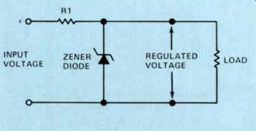
Figure 23. A shunt zener diode voltage regulator Shunt Voltage Regulators
A simple shunt voltage regulator using a zener diode is shown in Fig.23. You will re member that a zener diode is operated under reverse-bias conditions and that once the diode breaks down and begins conducting, changes in the current through it result in only a very small change in the voltage across it. As the current through the diode varies to compensate for changes in the load current or input voltage, there will be some change in the out put voltage, but the change will be much less than it would be without the diode regulator.
The regulated voltage will be equal to the input voltage less the voltage drop across R1.
The value of R1 is selected so that, under normal operating conditions, the current through the zener diode will be about 20% of the current flowing through the load. If the input voltage increases, the current through the zener diode will increase so that the voltage drop across R1 will increase. This will keep the regulated voltage constant. If the input voltage decreases, the current through the diode will decrease so the voltage drop across R1 will decrease.
If for any reason the load current increases, the current through the zener diode will decrease once again, keeping the voltage drop across R1 almost constant. If the load current decreases, the zener diode current increases, keeping the current through and the voltage drop across R1 almost constant.
One problem with silicon zener diodes is the effect that temperature has on the reverse breakdown voltage. Zener diodes with break down ratings of less than about 6 volts have a negative temperature coefficient. The breakdown voltage of a diode with a negative temperature coefficient decreases as the temperature increases. Zener diodes with a voltage breakdown above 6 volts have a positive temperature coefficient. This means that the breakdown voltage increases with increases in temperature. At about 6 volts, the zener diode has almost a zero temperature coefficient. The 6 volt zener is very stable with temperature changes.
A temperature-compensating zener, designed for use above 6 volts, can be built by connecting a zener diode and a normal silicon diode in series. The temperature coefficient of a conventional forward-biased diode is negative, and that of a zener diode above approximately 6 volts is positive. Therefore, the possibility of one diode compensating for a change in the other exists when they are connected back-to-back as shown in Fig.24(A). Diode D1 is a silicon diode connected in the forward-biased direction; D2 is a zener diode connected in the reverse-biased configuration. Sometimes both diodes are packaged together, as shown in Fig.24(B). The dot end should be connected to the positive terminal so that the zener diode is properly back biased.
A silicon diode has a voltage drop of approximately 0.7 volt across it when it is con ducting. When it is in series with the zener, the drop across the combination will be 0.7 plus the zener voltage. For example, an 8.2 volt zener in series with a series diode regulates the voltage to 8.2 + 0.7 = 8.9 volts.
The simple shunt regulator shown in Fig.23 is quite satisfactory and economical, as long as the current requirements of the load are not too high. One-half watt and one watt zener diodes are inexpensive, have a low resistance, and will provide good regulation. If the power consumed by the load does not exceed 5 watts, this type of circuit works well. In higher power applications we must use high- wattage zeners. They are expensive and have a fairly high resistance, providing less effective regulation than the low-power units.
When the current requirements exceed those that can be regulated by low-wattage zener diodes, it is better to use a series voltage regulator circuit.
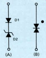
Figure 24. (A) Connections for a temperature-compensating zener diode,
and (B) its schematic symbol.
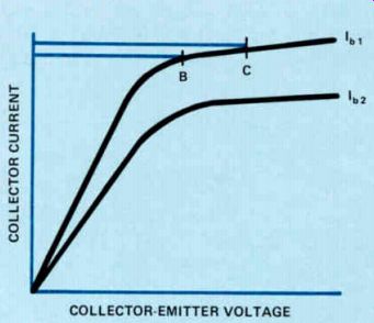
Figure 25. Transistor characteristic curves.
Series Voltage Regulators
Before going into the series regulator, let's look at the transistor characteristic curves shown in Fig. 25. Each curve is a plot of collector current versus collector-emitter voltage for a given base current. Once the collector-emitter voltage reaches a certain value, any further increase causes little or no change in collector current for a given base current. If the base current changes, the collector current changes appreciably; if the base current remains constant, the collector current remains almost constant even with wide changes in collector voltage.
As an example, notice that on the curve for I_b1 that if the collector-emitter voltage changes from point B to point C, there is little change in collector current. Since the resistance of a transistor is equal to the collector-emitter voltage divided by the collector current, the transistor resistance must increase as the collector-emitter voltage increases. The transistor therefore acts as a variable resistor.
We use this characteristic of a transistor in the series-regulated supply shown in Fig.26.
Notice that the transistor base voltage is held at a fixed value by the zener diode D1. Let's see what happens if the dc input voltage increases.
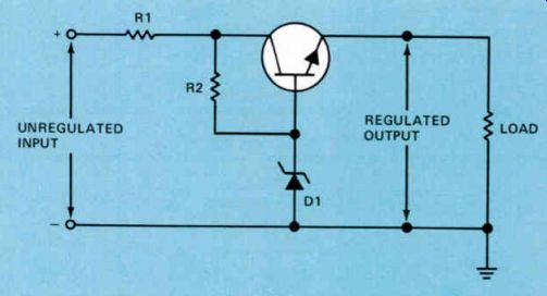
Figure 26. A simple emitter-follower series voltage regulator.
When the dc input voltage increases, the current flowing through the series circuit consisting of R2 and D1 will increase. The voltage across diode D1 will remain essentially constant and the voltage drop across R1 will increase. The base voltage applied to the transistor will remain essentially constant.
At the same time, the collector-emitter voltage of the transistor will increase because of the increased input voltage. Since the base voltage remains constant, there will be little or no increase in collector current and hence little or no increase in emitter current. The resistance of the transistor increases so that the voltage across the load will remain essentially constant. If the input voltage should drop, the opposite happens. The voltage drop across R1 goes down, but the base voltage remains almost constant. The resistance of the transistor will decrease so that the voltage across the load will remain essentially constant.
Of course, if the input voltage should change, the current through D1 will change, so there will be some small change in the voltage across it. This will result in a slight change in the collector and emitter currents of the transistor; the voltage across the load will change slightly, but far less than it would without the series regulator. More elaborate circuits can be used to provide better regulation.
Feedback Voltage Regulators
Figure 27 is a block diagram of an improved series regulator, often called a feedback regulator. In this circuit, the sampler is a sensing element, usually a resistor voltage-divider network. It samples a part of the output voltage. This sample is usually set equal to a reference level. The reference voltage establishes a standard for this circuit against which the output will be compared. The sample taken from the output and the reference are both applied to an error detector, which compares the two.
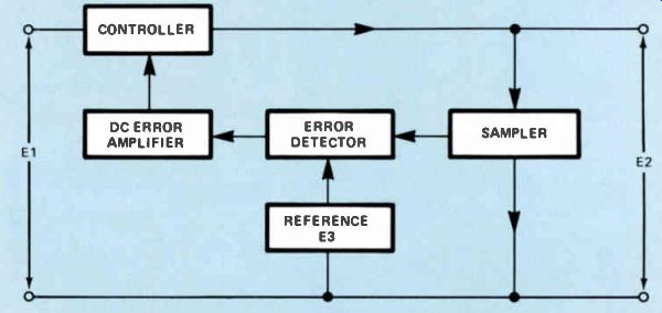
Figure 27. Block diagram of a feedback regulator.
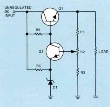
Figure 28. Simple feedback voltage regulator.
Any fluctuation in the output produces a positive or negative dc voltage at the output of the error detector. The error voltage is amplified and applied to the controller (usually a series transistor acting as a variable resistance). The amplified error signal changes the bias on the control element in Fig.27 to shift the output back to the desired level.
The simplest form of feedback voltage regulator is shown in Fig.28. The series-pass transistor, Q1, is an emitter follower similar to that used in the regulator discussed earlier. Here the base voltage of the series-pass transistor is controlled by the error amplifier Q2. Q2 performs the functions of comparison, error detection, and amplification.
A sample of the output voltage is taken from the output through the voltage divider made up of R1, R2, and R3. This sample is applied to the base of Q2. The emitter of Q2 is biased by the zener diode DI and through resistor R4 to provide a fixed voltage at the emitter of Q2. The output voltage sample and the zener reference voltage are compared by Q2. The current flowing through Q2 is a function of the output voltage and the zener voltage. The base bias for Q1 is obtained from resistor R5. The current through this resistor is a combination of the base current of Q1 and the current from the collector of Q2. A change in the output voltage will cause a change in the base of current of Q2, which in turn changes its collector current. This causes the base current of Q1, and hence its collector current, to vary. By changing the conduction of Q1, the output voltage will be adjusted to compensate for the original output change.
Assume that because of some line or load variation, the output voltage increases. This will cause an increase in the voltage occur ring at the base of Q2. The base current of Q2 will increase. In turn, the collector current of Q2 increases. This brings about a reduction in the base current of Q1. Since Q1 conducts less, its effective resistance will increase. This causes the output voltage to decrease. As you can see, the original output voltage increase is corrected. A decrease in output voltage causes the base and collector current of Q2 to decrease. Therefore, the base current of Q1 will increase. Q1 will conduct more, and its effective resistance will decrease. This results in an offsetting increase in the output voltage.
Resistor R2 in the output voltage divider is a potentiometer. This permits you to adjust the base current of Q2. The voltage at the base of Q2 is essentially fixed at a value equal to the zener voltage plus the emitter-base drop of Q2. Despite the changes in the adjustment of R2, the voltage between the base of Q2 and ground will remain essentially constant.
However, the base current of Q2 will vary as R2 is adjusted. Adjusting R2, therefore, controls the collector current of Q2 and the base current of Q1. This in turn varies the output voltage. R2, then, is a control that can be used to adjust the output voltage to the desired level. Once it is set, the circuit will automatically maintain the output voltage at this desired value.
Any hum voltage on the unregulated dc input or change in the unregulated dc input will cause some change in the regulated out put voltage in the circuit shown in Fig.28. A change in the input voltage will change the current through the zener diode D1 and R4 so there will be some slight change in the voltage across D1 which will change the emitter voltage of Q2. Similarly, a change in the unregulated dc input will cause the current through R5 and hence the base current of Q1 to change. This also will affect the regulated output voltage. These two problems can be overcome or greatly reduced by modifying the circuit slightly as shown in Fig.29.
Notice that in the improved feedback voltage regulator R4 has been moved from the unregulated input to the output. This will result in a more constant current through the zener diode and R4 so that the voltage applied to the emitter of Q2 will be essentially constant.
The resistor R5 in Fig.28 has been replaced by the constant-current source made up of D2, Q3, R5, and R6. Notice that Q3 is a PNP transistor, so current flows from the collector of Q2 and the base of Q1 to the collector of Q3.
Electrons flow from the emitter of Q3 through R6 to the power supply output. Notice that the zener diode, D2, holds the base of Q3 constant, keeping the current through this transistor constant.
In addition to preventing ac ripple and changes in the input from changing the base current of Q1, the constant current source also improves the load regulation of the circuit.
In order to provide perfect regulation, the sum of the base current of Q1 and the collector current of Q2 should be constant. An increase in the collector current of Q2 will then result in an equal decrease of the base current of Q1 and vice versa. If the sum of the currents is not constant, poor regulation will result. By using a simple resistor for this bias source, as we did in Fig.28, we create variations in the output voltage that will affect the collector current of Q2. These variations should be offset by equal and opposite variations in the base current of Q1. These current changes can change the voltage across the resistor R5 in Fig.28. As a result, the current it supplies changes, forcing the circuit to compensate for changes in the bias current as well as output voltage variations. Naturally, this reduces the effectiveness of the regulator in compensating for load variations. The constant-current source eliminates this effect.
A further improvement in the basic feed back regulator can be obtained by increasing the gain of the error amplifier circuit. Very small changes in the output voltage must be amplified sufficiently to provide control to the base of the series-pass transistor. The higher the gain of the circuit, the more control small variations in output voltage will have on the series-pass transistor.
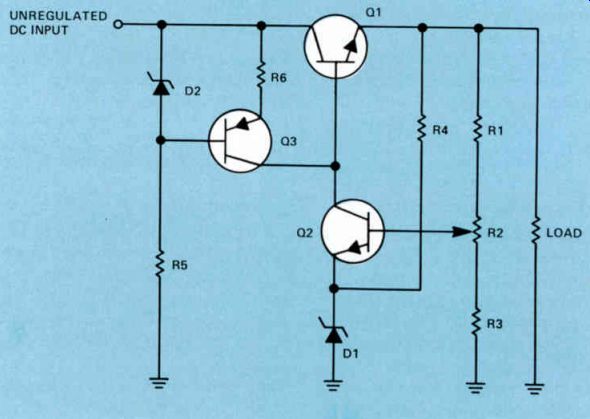
Figure 29. An improved feedback voltage regulator
Integrated Circuit Voltage Regulators
While some electronic voltage regulator circuits are still constructed with discrete components, more and more integrated circuits are being used in this application. Using modern integrated circuit technology, it is possible to construct the entire feedback regulator circuit on a single chip of silicon. Many integrated circuit voltage regulators are available. Some of these devices require absolutely no external components other than the usual power supply parts for proper operation.
Three-Terminal Regulators. One of the simplest and most widely used integrated circuit voltage regulators is the three-terminal regulator. This device is packaged in a standard power transistor housing and, like any bipolar transistor, has three terminals. The terminals on the regulator are the input, to which is applied the unregulated dc voltage, the regulated output voltage terminal, and the common or ground terminal. These are terminals 1, 2, and 3, respectively, in Fig.30. As you can imagine from the description, the device is extremely easy to use. The unregulated voltage from the power supply is applied between the input terminal and ground.
The load is connected across the output terminal and ground. Such regulators are available in a wide range of current and voltage ratings. Typical regulated output voltage ratings are 5, 6, 8, 12, 15, 18, and 24 volts, both positive and negative, with current ratings as high as 1 ampere.
Three-terminal regulators are usually used as remote regulators on printed circuit boards to supply the voltage requirements of the circuits on individual printed circuit boards. This arrangement allows a relatively inexpensive unregulated power supply to supply the power needs for a collection of printed circuit boards as might be present in any large electronic system. The regulators on the individual circuit boards need to handle only the modest power requirements of the circuitry on their own circuit boards.
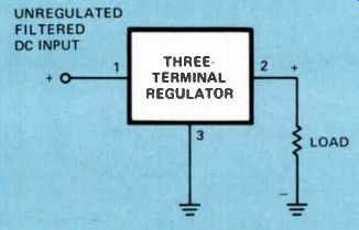
Figure 30. Typical three-terminal IC regulator.
The three-terminal regulators usually contain protective circuitry that causes the de vice to shut down when its internal temperature becomes too high. This might happen if too much current were drawn from the load or if the input voltage were too high, resulting in a large power dissipation in the regulator. In most instances, the regulator will resume normal operation when the cause of the excessive heat is removed.
Integrated circuit voltage regulators are replacing discrete component regulators Because they are smaller and require less space (you have to make only three connections to the regulator and the entire circuit is wired), they are usually provided with their built-in overload protection, and they are consider ably cheaper than regulators using discrete components.
Adjustable Regulators. Adjustable IC voltage regulators are also available. A typical one is the Fairchild 723. This device can supply positive or negative output voltages.
The output voltage can be set to any value between 2 and 37 volts. The IC can supply an output current up to 150 mA. You do not have to know how these devices work, but simply that they are available. They are more expensive than the fixed voltage regulators, but in some applications the increased cost may be justifiable.
Voltage Regulator Performance
Voltage regulator performance is measured in several ways. You do not have to know all of them, but there are several important specifications with which you should be familiar.
Line Regulation. The percentage a regulated dc output voltage may change for a change in ac input voltage is called line regulation, or regulation factor. Line regulation is one of the most important regulator parameters. It is usually measured with a constant load current so variations in the load do not come to play. Line regulation can be expressed as follows: % line regulation equals change in dc output voltage x 100 change in ac input voltage If for an input change of 5 volts, the output were to change by 50 millivolts (0.05 volt), the regulation factor would be:
0.05 x 100 = 1% 5
It is important to notice that the smaller the percentage of line regulation, the better the job the voltage regulator is doing.
Load Regulation. The percentage of change in regulated output voltage for a change in load from zero to the maximum load current specified is called the load regulation. The load on the regulator is changed from no load (open output) to full load where maximum safe current is drawn and the change in out put voltage noted. Load regulation is as important as line regulation; it is a true mea sure of how well the regulator maintains the constant voltage with varying loads. Load regulation is expressed as follows: % load regulation equals change in output voltage x 100 full load output voltage.
The change in output voltage in this formula is simply the difference between the no load or open circuit output voltage and the output voltage with maximum or full load.
For example, assume we have a power supply with a no-load voltage of 5 volts. If we place a full load on the supply and the output drops to 4.75 volts, we have 5 - 4.75 % load regulation = x 100 4.75 0.25 x 100
4.75 25 = 4.75 = 5.263%
Once again, the lower the percentage of load regulation, the better the regulator is working. In other words, a power supply with a load regulation of 1% has better regulation than power supply with a load regulation of 5%. Ripple Rejection. Any ripple or hum voltage fed from the filter network to the voltage regulator appears to the voltage regulator just like a change in the input voltage. The regulator will try to maintain the output voltage constant. A measure of the capability of the regulator to reduce ripple voltage is termed ripple rejection. How well the regulator rejects this ripple is the ripple rejection factor. Ripple voltage is actually a rapid change in the dc input to the regulator; the regulator sees it as any other input voltage variation and, therefore, attempts to compensate for it. The regulator substantially reduces the output ripple. This is true of any regulator circuit.
Summary
One important thing for you to remember about voltage regulators is that there are two types: shunt voltage regulators and series voltage regulators.
Shunt voltage regulators are normally used when the power requirements of the load are low. While simple shunt regulators are quite satisfactory for maintaining the voltage constant, they are very inefficient since all the current flowing through them is wasted.
Series regulators are more efficient than shunt regulators and they can be used for higher power requirements.
Series regulators with some type of error detection and feedback provide better regulation than simple series regulators.
The trend in modern series voltage regulators is to use three-terminal integrated circuit regulators. They are available in a wide number of voltage ratings.
They provide effective regulation, take up less space than regulators made up of discrete components, and are generally less expensive. In addition, they usually have some type of overload protection built into them so that in the event of an overload they simply shut down.
Self-Test Questions
Why is a shunt regulator inefficient?
Will the voltage across a properly biased zener diode remain constant if the current through the diode changes?
How does the series transistor in a series voltage regulator control the output voltage?
Name three advantages of the three terminal IC regulator over series regulators using discrete components.
Which regulator provides better load regulation, one with a load regulation of 5% or one with a load regulation of 2%?
-----------------------------
CIRCUIT PROTECTION
Every power supply requires some protection from overloads. When excessive current is drawn from the power supply, there is a chance of damaging the regulators, rectifiers, power transformer, and other components.
Most power supplies are designed to with stand some overload. However, when they are excessively overloaded, or overloaded for long periods of time, expensive damage can result.
For that reason most power supplies are protected with fuses or circuit breakers that remove the overload before damage can occur.
Fuses
A fuse is a part connected in series with the electric circuit it is to protect. It protects the circuit by melting and opening if an excessive current passes through it. Only when overloaded does the fuse operate, or "blow." Otherwise, it performs no function in the normal circuit other than completing the path for current flow.
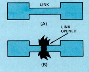
Figure 31. Fuse operation showing (A) a good fuse, and (B) a blown fuse.
Fuses are made from metal alloys which, when made to a precise width and thickness, will melt and open as a predetermined current passes through. Figure 31 illustrates this.
The links in fuses designed to operate at currents of about 1 ampere or more are shaped like the link shown in Fig. 31. Fuses designed to operate at lower currents are generally made of a round piece of fuse wire.
Fuses are usually made with the link strung between two metal end caps, the housing being a glass tube. Some of the higher current units use a ceramic tube housing for splatter protection and heat dissipation. The glass envelope offers an advantage over the opaque ceramic: the fuse condition is visible.
It is often impossible to determine whether or not the fuse is good by visual inspection in the case of a very low current fuse because the fuse link is so thin. Any doubtful fuse can be checked with an ohmmeter. If the fuse is good, there will be a low resistance across it.
Fuses come in a wide range of standard values and can be used in either ac or dc circuits. Whenever you have to replace a blown fuse, never use one having a higher current rating than originally specified by the manufacturer. If you do, you will forfeit the protection the fuse is supposed to supply.
There are three different types of fuses used in electronic equipment: fast-blow, very fast blow, and slow-blow. The most commonly used is the fast-blow type and, unless otherwise specified, you can assume that a fuse is of this type. Fast-blow fuses are used in many solid state circuits where transistors, ICs, or diodes would be damaged unless the overload is re moved quickly.
The very fast-blow types have been developed recently for critical semiconductor circuits where extremely rapid overload removal is needed. The very fast-blow fuse will blow in about 1/10 of a second or faster when 100% overloaded.
---------------------
A slow-blow fuse is one that will open if it is subjected to a continuous overload; it is essentially immune to momentary overloads.
This fuse contains an element that is heat sensitive and it will open when it gets hot enough from self-heating. It is because of the element's heating delay that the fuse will not blow when it is temporarily overloaded. Most of these fuses contain a small spring that helps to pull apart the fuse element rapidly when it does melt.
Slow-blow fuses are used in any circuit when temporary overloads occur as a normal part of operation. A good example is their use in motor circuits where the starting current is very high for a few seconds, but operating current is relatively low. An ordinary fast blow fuse would blow every time the motor is started because of the high motor starting current.
Circuit Breakers
Circuit breakers work much like fuses--they open the circuit when the current exceeds a predetermined value. They have the advantage over fuses in that they can be reset once the overload has been removed. Fuses must be discarded and replaced once they blow.
There are two basic types of circuit breaker.
One type has a bimetallic strip that is surrounded by a coil through which the current passes. If the current through the coil be comes too high, the heat produced causes the bimetallic strip to bend. The motion of the bimetallic strip is transferred to a mechanical linkage that releases a catch used to hold the switch contacts together. The contacts are pulled apart by a spring. Once the overload is removed, pressing the reset button will en gage the catch that holds the contacts together.
A different type of circuit breaker uses an electromagnet to operate the release. If excessive current flows through the coil of the magnet, the magnet field will be sufficient to pull the core into the coil. This actuates a mechanism that releases the catch that holds the contacts together.
You do not have to know all the details of how a circuit breaker works, you simply have to know the purpose for which it is used, and if you have to replace one, be sure to get one with the same current rating as the original.
Occasionally you will encounter a circuit breaker that works when the equipment is first turned on and then opens after it has been in use for some time, even though the current through the circuit breaker is nor mal. When this happens, the circuit breaker is defective and you must replace it.
Electronic Protection Circuits
Fuses and circuit breakers are electro mechanical protection devices. While they provide adequate protection in many cases, they operate too slowly in some other cases.
Where more rapid protection is required, electronic protection circuits are used.
A simple circuit for protection against momentary voltage overloads is shown in Fig.32(A). Here we have a 5 volt power supply with a 5.6 volt zener diode connected across it. As long as the power supply voltage re mains 5 volts, the 5.6 volt zener diode connected across it will not conduct in its reverse direction.
Since the diode does not conduct, it draws no current from the supply; it is essentially inactive. If some overvoltage should occur, the diode will conduct when the voltage reaches 5.6 volts. Because of its constant voltage characteristic, it tends to hold the voltage across the power supply to 5.6 volts. Thus the equipment is protected. The additional 0.6 volt causes no damage or trouble.
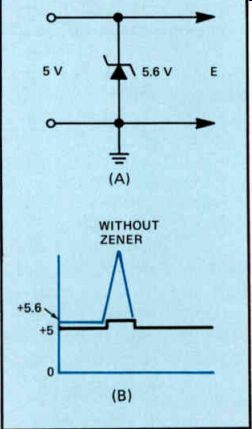
Figure 32. (A) A zener diode for overvoltage protection, and (B) how
the zener clamps overvoltage conditions.
The zener diode is an extremely fast-acting device; even transient overvoltage conditions will be detected. If some high-amplitude, short duration, power line transient should pass through the supply and appear on the output line, the zener diode will conduct momentarily and clamp that overload condition to 5.6 volts. Figure 32(B) shows such a condition. A zener diode connected in this way provides excellent and inexpensive protection from momentary overload conditions.
For momentary overload conditions, the zener diode provides adequate protection. It may be insufficient, however, to protect against large or sustained overvoltage. In these cases, the zener diode must have a substantial power rating to withstand the current that will flow during the overload condition. In many situations, zener diodes with the desired power rating are simply not available. Other provisions must then be made to protect against overvoltage conditions.
Such a circuit is shown in Fig.33. Commonly referred to as a "crowbar," this circuit consists of a silicon-controlled rectifier (SCR) and a current source that senses the voltage on the power supply lines. Normally, the SCR and the current source transistor (Q1) are not conducting, and the normal supply voltage is applied to the equipment.
A silicon-controlled rectifier is a diode with a cathode and an anode like any other diode.
But it also has a third element called a gate.
The SCR will not conduct, even when there is a positive voltage applied to the anode, until it is turned on or "fired" by a positive voltage to the gate. Once the SCR begins conducting, it will continue to conduct even if the positive voltage is removed from the gate. The only way you can stop current flow through the SCR is to momentarily remove the positive voltage applied to the anode.
In the circuit shown in Fig.33, the zener diode D1 has a breakdown voltage equal to the voltage at which you want overvoltage protection to occur. This will be somewhat above the normal value of E1. Under normal operating conditions, the voltage E1 is not high enough to cause the zener to conduct, so there will be no current flow through it or through R1. With no current flow through R1 there will be no voltage drop across it; the base and emitter of Q1 will be at the same potential. This means that Q1 will not have any forward bias across the emitter-base junction and therefore will not conduct; it will act like an open circuit. Thus there is no voltage applied to the gate of the SCR and the SCR does not conduct.
The base of Q2 is connected through R2 to + V. This forward biases Q2 so current flows through it and through the relay coil. Current through the relay coil will energize the relay so its contacts will close and power is applied to the primary of the power transformer through the closed relay contacts.
If the value of E1 rises and exceeds the breakdown voltage of zener diode D1, current will flow through the diode to the cathode and through R1 to +V. Current flowing through R1 will develop a voltage across it so the base of Q1 will be negative with respect to the emitter. Remember that this is the condition needed to provide forward bias across the emitter-base junction of the PNP transistor Q1.
When Q1 turns on, it acts like a short circuit so that the gate of the SCR is connected through Q1 directly to +V. This causes the SCR to fire so a high current begins flowing through it. This places a momentary short across the power supply so that the value of El drops. When this happens, the voltage of the base of Q2 will drop practically to zero and Q2 will stop conducting. When Q2 stops conducting, the current through the relay coil will drop to zero and the relay contacts will open, removing the ac voltage from the primary of the power transformer. This will, in effect, shut down the power supply.
The speed at which the crowbar circuit works depends primarily on the speed of the relay.
There are fast-acting relays available that will open in less than a millisecond so the input voltage to the power supply can be removed very quickly, before any damage can occur.
Diode D2 connected across the relay serves no useful purpose when the relay is energized and its contacts closed. However, when Q2 stops conducting, the sudden drop in current through the relay coil will induce a voltage that keeps this current flowing. The polarity of the voltage will be such that D2 conducts, causing this voltage to disappear rapidly so the relay will open.
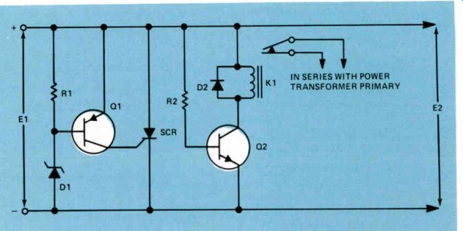
Figure 33. SCR crowbar overvoltage protection circuit.
----------------------
Summary
The important thing to remember about fuses is that if you have to replace one, you should replace it with a fuse of the same type and current rating as the original.
Circuit breakers perform the same function as fuses, but they are mechanical devices. Once the overload has been removed, they can be reset so that the circuit then will be complete. If the circuit keeps opening even though the current through it is normal, it is a sign that the circuit breaker is defective and should be replaced.
Electronic protection circuits work much faster than fuses or circuit breakers. A zener diode will provide protection against short-term overvoltage conditions. Where large or sustained over voltage conditions may exist, a circuit such as the crowbar overvoltage protection is normally used.
Self-Test Questions
Can you use a slow-blow fuse in place of a fast-blow fuse?
Should you use a 2 ampere fuse in place of a 1 ampere fuse?
If a circuit breaker trips after one hour's operation and the current through it is normal, what should you do?
If a 6.8 volt zener diode is used for overvoltage protection in a 6 volt power supply, will the diode conduct if the voltage rises to 6.5 volts?
In addition to a positive voltage on the anode of an SCR, what other condition must be met before the SCR will conduct?
When an SCR begins conducting, how can you stop it from conducting?
ANSWERS TO SELF-TEST QUESTIONS
1. The primary winding.
2. The secondary winding. In a transformer, the ratio between the primary voltage and the secondary voltage depends entirely upon the ratio of the turns on the primary winding to those on the secondary winding.
If the secondary winding has more turns than the primary winding, the transformer will be a step-up transformer; if it has fewer turns, it will be a step-down transformer.
3. The secondary winding.
4. The primary winding.
When a load is connected across the secondary winding of a transformer, the winding will supply power to the load. The amount of power will depend upon the secondary voltage and the load resistance. The power supplied by the secondary winding must come from power taken by the primary winding from the power line. If the secondary is supplying the power at a voltage lower than the primary voltage, then the secondary current will be higher than the primary current. On the other hand, if the secondary winding is supplying the power at a voltage higher than the primary, then the secondary current will be lower than the primary current.
5. The efficiency of a transformer is the ratio of the power supplied to the secondary load over the power consumed by the primary times 100. If a transformer supplies 95 watts to the secondary and takes 100 watts from the power line, then its efficiency will be 95 divided by 100 times 100 equals 95%.
6. Copper losses are due to the resistance of the wire used to wind the various coils in the transformer. The copper loss in each winding is equal to the current squared flowing in that winding times the resistance of the winding.
7. To reduce losses due to eddy currents.
8. Eddy current losses, hysteresis losses, and flux leakage losses.
9. Since the primary and secondary windings of an autotransformer are continuous, that is there is only one winding, the autotransformer does not isolate the load from the power line.
10. 60 per second. Since a half-wave rectifier provides one pulse per cycle, there will be 60 pulses per second on the 60 Hz power line.
11. It is difficult to filter to pure de. This is primarily due to the fact that a pulse flows during one half-cycle, but there is no current flow during the next half-cycle.
12. For a given de output voltage, the transformer secondary need have only half as many turns as the full-wave rectifier circuit shown in Fig.10.
13. The bridge rectifier has the disadvantage that it requires four rectifiers, whereas a full-wave rectifier circuit with a tapped secondary re quires only two.
14. In the full-wave voltage doubler circuit shown in Fig.13, the load is connected across C1 and C2 in series, so these capacitors are continually supplying power. In the half-wave rectifier circuit, current is supplied to the load only during the part of the half-cycle when terminal A is positive with respect to terminal B. 15 It may charge to the peak of the ac line voltage which in the case of a 120 volt power line is approximately 170 volts.
16 It may be used in applications where the current drain from the power supply is low.
17 The RC pi-type filter provides much better filtering, particularly if there is any appreciable current drawn from the power supply.
18 The inductance in an LC filter has a much lower dc resistance than the resistance in an RC filter. In addition, in most cases the inductive reactance of the choke in an LC filter is much higher than the resistance of the resistor, so that better filtering is provided.
19 The filter capacitors in Fig.20(B) are connected with the opposite polarity to those in Fig.20(A) because the rectifier is reversed.
20 For a given dc output voltage, the power transformer in the rectifier circuit shown in Fig.21 must have twice as many turns on the secondary winding as the transformer used with a bridge rectifier circuit.
21 The highest dc output voltage will be available between terminals 1 and 2 in the circuit shown in Fig.22.
22 D1 and D4.
23 A shunt regulator is inefficient
Because the current passing through it serves no useful purpose insofar as powering the equipment is concerned.
24 Although the voltage across a properly biased zener diode changes very little when the current changes through it, the voltage does change.
25 The resistance of the series transistor varies to control the output voltage in a series voltage regulator.
26 When compared to a series voltage regulator using discrete components, the three-terminal IC regulator is less expensive, uses less space, usually has some form of overload protection, and is quickly installed in the circuit.
27 The lower the percentage regulation of a voltage regulator, the better the regulation. A regulator with a load regulation of 2% provides better regulation than one with 5% regulation.
28 A slow-blow fuse may never be used in place of a fast-blow fuse.
29 You should not use a 2 ampere fuse in place of a 1 ampere fuse. A blown fuse should be replaced with one having the same rating as the original fuse.
30 The circuit breaker is probably defective and should be replaced.
31 A 6.8 volt zener diode used to protect a 6 volt power supply will not conduct if the voltage rises to 6.5 volts.
32 The SCR must also have a positive voltage applied to the gate before it will begin conducting.
33 Once an SCR begins conducting, it will continue to conduct even after the gate voltage is removed. The only way you can stop it from conducting is to temporarily remove the anode voltage.
----------------------
This is Lesson Number 2229.
Make sure you print your name, student number, and lesson number in the spaces provided on the Lesson Answer Form. Be sure to fill in the circles beneath your student number and les son number.
Reminder: A properly completed Lesson Answer Form allows us to evaluate your answers and speed the results and additional study material to you as soon as possible. Do not hold your Lesson Answer Forms to send several at one time. You may run out of study material if you do not send your answers for evaluation promptly.
LESSON QUESTIONS
1. If the primary-to-secondary ratio of a step down transformer with losses is 10 to 1, and the secondary winding is supplying 100 watts to the load, the primary power will be:
a. 10 watts.
b. 100 watts.
c. 1000 watts.
d. Somewhat over 100 watts.
2. The core of a transformer is made of laminations rather than a solid piece of steel in order to:
a. Keep eddy current losses at a minimum.
b. Reduce hysteresis losses.
c. Reduce flux leakage losses.
d. Reduce copper losses.
3. If the primary-to-secondary turns ratio in a transformer is 1 to 5 and the current supplied to the load by the secondary is 1 ampere, the primary current will be approximately:
a. 1 / 5 ampere.
b. 1 ampere.
c. 5 amperes.
d. 10 amperes.
4. The primary reason for using an auto transformer over a transformer with two separate windings is that:
a. It is a better step-up transformer.
b. It is a better step-down transformer.
c. It is more efficient.
d. It is cheaper.
5. Which type of rectifier circuit produces the least ripple and the best regulation in a power supply?
a. Half-wave.
b. Voltage doubler.
c. Full-wave.
d. Simple capacitor filter.
6. In a simple capacitor-type filter such as shown in Fig.14, current flows through the rectifier for:
a. One half-cycle.
b. More than one half-cycle.
c. Less than one half-cycle.
d. As long as the capacitor is discharged.
7. The advantage of an LC filter such as shown in Fig.18 over an RC filter such as shown in Fig.16 is:
a. The output voltage will be higher.
b. Lower hum voltage at the output.
c. There will be less voltage drop across the choke.
d. All three of the choices given are correct.
8. In the power supplies shown in Fig.20(A) and (B), R2 is connected between the diode and the power line to:
a. Provide better filtering.
b. Reduce the voltage across C1.
c. Limit the initial charging current through D1.
d. Reduce the voltage across D1.
9. In Fig.29, if the output voltage decreases, the collector current of Q2:
a. Increases.
b. Decreases.
c. Remains the same.
10. What is the qc load regulation of a power supply whose open circuit output voltage of 24 volts drops to 20 volts under full load?
a. 16.7%.
b. 83.3%.
c. 20%.
d. 80%.
NRI Schools YOUR REPUTATION
Success in business depends on a number of things, but your reputation is probably the most important of them. Your sense of fair play and of honest dealing will determine your reputation, whether you run your own business or work for someone else. To help you get started on the right track, here are a few of the business rules you should memorize: Keep your promises. Make it standard policy to only make promises you are reasonably sure you can keep.
Keep accurate records. Only records can show what your profits are, and what the tax bill is. Adequate records are essential to show you how to adjust your charges to be fair both to yourself and to your customers.
Be honest in all your dealings. Honesty goes far beyond dollars and cents; it includes fairness to your employees and clients, telling the truth in your advertising, guaranteeing your work and your merchandise, and being reasonable in dealing with your suppliers.
A good reputation is essential to a good business. With it, you are well on the road to success. Without it, you won't get very far.
| Top of Page | PREV | NEXT | Article Index |