AMAZON multi-meters discounts AMAZON oscilloscope discounts
Student's Guide for Computer-Aided Troubleshooting
-------------------
Table of Contents
Introduction
What You Need to Know
How to Use this Manual
What You Get
What You Must Have
Installing the Program
Installing on a Network
Installing with SHARE.EXE
Removing the Program
Operating the Program
Mouse and Keyboard
Scroll Bar Buttons
Using the Program
Student Workdisks
Starting the Program
Running the Program
Menus and Screens
Using the Tools
Leaving the Program
Evaluating Yourself
Using the Tb Files
Factors to Consider
Additional Ways to Use the Program
The Problems
Objectives of the Program
Series Resistors
Series/Parallel Resistors
Resistor Bridge
R/C Combination
Answer Sheet
Acknowledgments
We wish to express our thanks to the staff of Heathkit Educational Systems. Their contribution to this team effort, in providing our students with quality educational materials, has been significant.
Introduction
Welcome to Computer-Aided Troubleshooting (CAT) from NRI Schools. NRI's DC Electronics Computer-Aided Troubleshooting Package is an interactive software program. With this troubleshooting software, you, the student, actually interact with "life-like" equipment mal functions. Full-color animations bring a sense of realism to problem-solving interactions. You are placed in a challenging electronics troubleshooting environment where you are not restricted simply to reading from a textbook. The program draws you into actual troubleshooting situations where you participate in complete safety and privacy. It provides you with both rewarding responses and constructive reinforcement. It is beneficial in that it provides an alternate, game-like method of teaching electronic troubleshooting.
The program offers you the opportunity to learn trouble shooting through fast-paced, hands-on simulations in a totally nonthreatening environment. By performing these experiments on the computer, you experience the real and practical side of electronics first-hand without worry of damaging equipment or yourself.
What You Need to Know
How to Use this Manual
This Student's Guide contains the documentation for the NRI DC Electronics Computer-Aided Troubleshooting program. This manual is written for the electronics student and the licensed site installer. It is assumed that the student or the installer has some limited computer knowledge of hardware and software, MS-DOS in particular.
This manual is divided into sections. The first, which you are reading, introduces the program and the manual itself. It contains a list of what is included in this product and the system requirements needed to successfully run the program.
The next three sections cover installing, operating, and using the program. Here, you'll find a simple installation procedure. It covers how to use the mouse, keyboard, and other features. These sections also tell you what you'll see in the program: menus, screens, windows, and tools.
The remainder of the manual contains further information and a detailed list of the troubleshooting examples, plus an answer for each problem. Because the answer to each of the troubleshooting problems is included in this manual, it is merely regarded as an adjunct, not as an examination, within your course. Thus, it will serve to enhance your troubleshooting knowledge and abilities.
What You Get
The NRI DC Electronics Computer-Aided Trouble shooting (CAT) program consists of:
• one or more 3.5" program disks
• one Student's Guide What You Must Have In order to run the CAT Program, the computer must be equipped with this hardware:
• 8088, 80286, 80386, 80486 or better processor (PC compatible)
• 640 KB or more of RAM
• Hard disk drive with 2 MB or more of free disk space
• EGA or VGA color monitor and driver
• One or more 3.5" floppy drives
• Mouse And this software:
• MS-DOS 3.1 or higher NOTE: Most of the functions of this program can be accomplished using only the keyboard. However, a mouse is required for a few operations and is highly recommended for efficient use of the program.
Installing the Program
Through a joint effort by NRI and Heathkit Educational Systems, this interactive electronic troubleshooting program has been made available. You will note appropriate credits as you start the program each time. If, by chance, some fault occurs in the installation or operation of this soft ware program, please contact NRI to obtain instructions concerning software correction or replacement procedures.
NOTE: The following installation instructions assume that the floppy drive designator on your computer is "A:." If your floppy drive is designated with a letter other than "A:," substitute that letter in the instructions.
To install the CAT program, do the following:
1. Insert Disk 1 into floppy disk drive A.
2. Type: A: Then press: RETURN (or ENTER) (This logs you onto drive A.) Type: INSTALL Then press: RETURN (or ENTER) This will start the installation program.
3. Before installation actually begins, the program first checks to make sure your computer's operating environment is compatible with the hardware/software requirements necessary to operate the CAT program (see "What You Must Have" for the hardware/software requirements). If your computer's environment is in compatible in any way, the program will NOT install.
In this case, a simple explanation as to the incompatibility will appear, and you will be returned to the DOS prompt.
A typical example is when the installation program does not find a hard drive with enough space for the program. In this case, you need to free up space on the hard drive before you run the installation program again.
If the installation program verifies that your system is compatible, it will continue with the installation.
4. Next, the program will ask you for the hard drive designator where you wish to install the program. The pro gram will list possible choices based on your system.
Simply press the letter for the drive where you want the program installed. Caution: Do not simply press the RETURN (or ENTER) key. You must press the letter of the desired drive.
You will then be given the opportunity to modify the installation path, or accept the default path. The default directory is CAT_DC. Unless you specify otherwise the program will be installed in this directory. If you prefer that it be installed in another directory use the backspace key to remove the CAT_DC path and enter the new path name.
5. The installation program will begin copying files from Disk 1 onto your hard drive. If there is more than one disk for the installation of the program, the installation process will ask you to insert the next disk after it finishes copying the necessary files from Disk 1. If you insert an incorrect disk, the installation process will notify you of this situation.
6. Continue this process until all disks have been inserted and copied. Some disks contain many files, and may take a few minutes to install onto your hard drive. When all the CAT disks have been installed, the installation program will automatically exit and return to the DOS prompt.
All of the program files will be contained in a subdirectory on your hard drive called "CAT_DC", or whatever path you specified during installation. To access that sub-directory, type in CD \ CAT_DC and press RETURN (or ENTER). To run the program, refer to the "Operating the Program" section of this manual.
Installing on a Network
The program may be installed on some types of networks.
Follow the preceding installation procedure to install the program on the server. Make sure each user is granted read, write, and file access to the directory the program was installed into.
For more information, refer to your network manuals and your distributor.
Installing with SHARE.EXE SHARE.EXE provides file sharing and locking to the MS-DOS operating system. If it is running on your computer while you are installing NRI Computer-Aided Instruction (CAI) software, it may cause the INSTALL program to not recognize that the correct disk has been inserted in the floppy drive. If you encounter this problem, check your AUTOEXEC.bat file and make sure SHARE is not being loaded. Once the CAI software has been in stalled, you can re-enable loading of SHARE.EXE if other software requires it to operate properly. The NRI CM soft ware should have no problem running with or without SHARE loaded. Only during installation might you encounter this problem.
Removing the Program The CAT program can be removed from the hard drive at any time. Simply delete the "CAT_DC" subdirectory (or whatever path you specified during installation) and its files from DOS.
--------
Operating the Program
Mouse and Keyboard
The CAT program can be operated by both a mouse and a keyboard. Both input devices control the position of an arrow cursor ( 4 ) over program selections. While a mouse is not absolutely required to run the program, we strongly recommend using one for the ease it provides in moving through the program. Also, there are a few operations that can be performed only with the mouse. For computers not equipped with a mouse, the arrow keys on the keyboard (<- t -> 1) move the arrow cursor. These arrow keys, as well as the rest of the keyboard, can be used in addition to a mouse.
Scroll Bar
There are times when the text information appearing in a window is much larger than the window itself. In these instances, all of the information can be reviewed by scrolling. This is accomplished with the help of a scroll bar, located at the edge (usually the left side for this pro gram) of the window. See figure 1 on the next page.
The scroll bar consists of an up direction button (located at the very top), a down direction button (located at the very bottom), and a slider button (located along the vertical path between the up and down direction button). The up and down buttons move the view of the text in small increments, while the slider allows for large, rapid movements of the text body. In order to use these buttons, the user must position the cursor over the button using the mouse,
-----------
1. This is text material.
2. Unseen text can be brought into view by moving the scroll bar downward.
Figure 1. Window with Scroll Bar.
-------------------
by using the cursor direction keys (<- is -> 1), page up (PgUp), and page down (PgDn) keys of the keyboard.
The student has three options for moving text:
1. To scroll text line by line, position the arrow cursor at either the up direction button or the down direction button, and click the mouse button (or press RETURN) once. Keeping the mouse button (or RETURN) depressed continues the scrolling action.
2. FOR MOUSE USERS. Position the arrow cursor directly on the slider button, then press and hold the mouse but ton. Vertical mouse movement positions the slider button to any desired location on the scroll bar. The text follows the movement of the slider button.
3. FOR KEYBOARD USERS. The PgUp, and PgDn keys may be used. PgUp and PgDn move the up/down direction button in large steps along the scroll bar.
Buttons A student can also move around in the program by using the mouse to press "buttons" as shown in figure 2 that appear on the screen. Buttons are activated by moving the cursor over the button and either clicking the mouse button or pressing RETURN. Using buttons is a procedure that students will pick up very quickly. When a button is selected in a screen, it depresses like a normal switch.
Figure 2. Window Button.
-------------
Using the Program Student Workdisks
To access and operate the installed program, you must provide and use a student workdisk. This disk is your "workbook" for the course. It records every move that you make as you progress through each troubleshooting experience.
Your workdisk must be inserted into a floppy drive to gain access to the program. The first time this is done, the program will ask for your name, and records that information on the disk. The disk then becomes unique for you and the course. Anyone else who tries to access the pro gram must have his or her own workdisk. If a student plans to continue through NRI's CAT series, another disk will be needed for each course. Any blank, formatted floppy disk may be used as a workdisk.
It is important that you take good care of your work disks, as the information on each disk is unique. Damaging or losing a disk will result in lost data.
Starting the Program To start the DC Troubleshooting program:
• Type: CD\ CAT_DC (or path specified in installation)
• Then press: RETURN (or ENTER) This logs you into the program subdirectory.
• Type: DC EXPLORE
• Then press: RETURN (or ENTER)
NOTE: This program is incompatible with some disk caching utility software. If you are having problems starting or running the program, make sure you are not running a utility such as smartdrv.sys. Also, because the program is graphics intensive, it requires about 500K bytes of free memory. You can free up memory by removing TSR programs such as screen savers, network drivers, etc.
Running the Program Opening Screens The program begins with an introductory graphics screen followed by an acknowledgment screen that includes copyright information. These two screen displays continue to alternate until the student clicks a mouse button or presses the RETURN key on the keyboard.
Check/Verify Workdisk Following the opening graphics screen, the program will verify the presence of a student workdisk. The pro gram must see a good workdisk before it will move on.
The following outline details the procedure for verifying workdisks.
I. Insert Workdisk. You will first see a window telling you to insert a workdisk (even if you have one already inserted). There are two buttons to choose from at this point.
1. Continue. Press this button if you have a workdisk inserted in one floppy drive for your system. This will move you to "Verify Workdisk," which is item II in this outline.
2. Exit to DOS. If you select this button, another window will appear asking to verify your exit. At this point, you have two choices:
a. Resume the Program. If you select this, the pro gram will move back to "Insert Workdisk," which is item I above.
b. Confirm Exit to DOS. If you select this, the pro gram will initiate an exit procedure, which includes creating and using a password. The "Leaving the Program" portion of the User's Guide explains this part of the program.
II. Verify Workdisk. The program will search the floppy drives installed on your system for a proper Student Workdisk. If you have two floppy drives, the program will search the "A" drive first. If it does not find a Workdisk in the "A" drive it will then search the "B" drive. There are three possible results during this operation:
1. New Correct Workdisk Present. If the program finds a good workdisk which has never been used before, the program will prompt the student to enter the first name, then the last name. Simply type in each name, and press RETURN. After the last name has been entered, that workdisk will be configured to work for that name, and for this course only. The program will then move to "Help Request," which is Item III in this outline.
2. Used Correct Workdisk Present. If the program finds a good workdisk which has been used before, the program will immediately move to "Help Request," which is Item III in this outline.
3. Incorrect Workdisk or No Workdisk Present. If the program fails to find a proper workdisk, a "Disk Read Error" message will appear on the screen.
You have two choices at this point:
a. Exit to DOS. You may select this option to return to a DOS prompt via the password screen as explained later in "Leaving the Program."
b. Continue. If you select this option, you will return to "Insert Workdisk," which is Item I in this outline.
III. Help Request. Once a proper workdisk has been installed and verified by the program, a window will appear offering the chance to review the information in the "Help" portion of the program prior to beginning. This option is offered regardless of whether the student has previously used the program or not.
There are two options at this point:
1. Access Help Window. By pressing this button, you enter the "Help" portion of the program. See the "Help Window" portion of this User's Guide for more information on the "Help" section.
2. Begin the Program. By pressing this button you move to the Main Option Menu of the program, which is the first menu.
Menus And Screens This troubleshooting program uses a series of menus that allows the student to move around smoothly and efficiently. Figure 3 shows the general path that the student follows through the program. The arrows point to the direction of the path, and the boxes contain other screen options and options for exiting the current screen.
------------
PI HELP SCREEN Defines each function and operation of the troubleshooting screen.
MAIN OPTION MENU
1. Series Resistors
2. Series / Parallel Resistors
3. Resistor Bridge
4. R / C Combination
5. Insert New Student Workdisk
6. Exit to DOS FAULT OPTION MENU
1. Fault #1
2. Fault #2
3. Fault #3
4. Fault #4
5. Random Fault
6. Previous Menu SUPPORT SCREENS
1. General Guidelines
2. The Problem (defined)
1 TROUBLESHOOTING SCREEN
1. Make voltage tests.
2. Make resistance tests.
3. Use Signal Generator to apply input.
4. Replace faulty parts with good ones.
5. Review the schematic.
6. Check the circuit board layout.
7. Ideas are available to assist you.
8. Check to see that the problem has been located and repaired.
9. Exit to main Menu.
Figure 3. Program Flowchart.
----------------
There are five main sections of the program. Each is explained in more detail in the following paragraphs: Main Option Menu Fault Option Menu Support Screens Troubleshooting Screen Help Screen Main Option Menu The Main Option Menu lists the four basic trouble shooting problems, as shown in figure 4. These are: Series Resistors, Series/Parallel Resistors, Resistor Bridge, and R/C Combination problems. The student selects one of these and proceeds to the Fault Option Menu. The Main Option Menu also offers the opportunity to change to a new student workdisk. This is done when changing students or when the present workdisk is full.
Fault Option Menu The student selects one of the faults or returns to the previous menu. The Random Fault is one of the four faults randomly picked by the program, as shown in figure 5.
Support Screens These are several screens of text that give general guidelines for troubleshooting DC circuits and describe the problem that the student has selected.
Figure 4. Main Option Menu.
Figure 5. Fault Option Menu.
General Guidelines Figure 6 shows the General Guidelines screen. This screen gives the student several important guidelines for troubleshooting DC Circuits. The student can use the scroll bar to move the additional guidelines into view.
This screen is displayed at the start of the first problem (Series Resistors) or it can be called up at any time from the Help Screen. The "Exit Guidelines" button takes the student to the next screen.
Figure 6. General Guidelines Screen.
Figure 7
Figure 8. Troubleshooting Screen.
Figure 9. Help Screen.
Problem Screen A typical Problem Screen is shown in figure 7. Problem screens are used to set up the troubleshooting scenario. They place the student in a real life servicing situation. Two or more problem screens explain the problem in enough detail to lead the student into the actual problem.
Troubleshooting Screen As shown in figure 8, this screen shows components on a circuit board. Students can turn power on and off to the circuit, make voltage and resistance tests, unsolder components and place them on the workbench, replace bad parts with good ones, look at the schematic or the component view, inquire to get troubleshooting ideas, and finally check to see if they have fixed the problem.
Help Screen The Help Screen, figure 9, may be accessed at any time by pressing the Fl key. To operate the Help Screen, just click on a tool or button. A short message indicates exactly what that tool or button does. You can also click on other screen areas such as the push-button switch, circuit board, workbench, meter display and test log. Here again, a message will tell you the purpose or function of the object selected.
When finished, click on the top EXIT button.
Using the Tools Students will spend most of their time in the Trouble shooting Screen. In this screen, they have access to a number of tools and buttons that allow them to simulate real world troubleshooting. Each of these tools and buttons are explained below.
Schematic / Component-View Button Soldering Iron This button allows you to examine either the component view of the circuit or the schematic. You switch from one view to the other by clicking on the button.
The Soldering Iron allows you to remove components from the circuit. It is selected by clicking on the button. When you select this tool, the cursor will be replaced by a small soldering iron icon. Simply click this icon on the component you wish to unsolder. The component will be automatically removed from the circuit and placed on the workbench.
Swap Component
The Swap Component tool allows you to replace a component with a "known good" component. When you select this tool, the cursor will be replaced by the soldering iron icon. Simply click the icon on the component you wish to replace or the space where a previously removed component belongs. The component will be automatically replaced with a "known good" component of exactly the same type as the one removed.
Idea or Hint Button
The hint button can give a little nudge if the student gets bogged down. When this button is clicked, a brief message is displayed where the workbench normally appears. The message remains until the mouse is clicked again. For each fault there are three different hints.
Check Button
This button is used to check the results of the repair. If the repair has been accomplished, a congratulations message will appear. Otherwise a "sorry, please continue" message is given.
Exit Button
The Exit Button allows you to leave the troubleshooting Screen at any time. It takes you to the Main Options Menu which was discussed earlier.
Power Button
This button controls power to the circuit under test. Click to turn power on. Click again to turn power off Generally there will be no voltages present in the circuit until power is turned on. Power should be turned on before making voltage measurements. Conversely, power should be turned off before making resistance measurements.
Board / Schematic Icon
This icon performs the same function as the Schematic/Component-View Button explained above. That is, it allows you to switch back and forth between the schematic diagram and the component view of the circuit under test.
Switch
Sometimes a circuit will contain a switch. In this case, the switch may be operated by clicking on its top button. This will open and close the contacts like a real switch. The switch will stay closed for as long as you hold down the mouse button.
The Workbench
The Workbench area serves two purposes. First, it is the area where components are placed when removed from the circuit with the soldering iron. Resistance and continuity checks can be made on components in this area. Second, it acts as a message display area. Both hint and warning messages appear here.
The Multimeter
The Multimeter is the primary instrument used to troubleshoot the circuit. This meter is an autoranging digital multi meter capable of measuring DC Volts and Resistance. The appropriate mode is chosen by clicking on the DC Volts or Ohms Button on the meter. The meter's input impedance is high enough that it will not load the circuit under test. The autoranging feature means that it will automatically choose the right range.
The meter also has an auto-blanking feature that blanks out the display until the digital count stops its runup. Therefore, quick changes in voltage or resistance may be missed. As with many digital meters, infinite ohms are indicated by a single 1 in the far left display.
To use the test leads, first click on the test lead button. Then click on the component lead and the test lead will connect itself there. To reposition the lead, click on the test lead and then on the new destination.
The Recording Log
The Recording log provides a record of all the measurements made. It automatically scrolls up as new measurements are added. By using the scroll arrows, measurements that have scrolled out of sight can be brought back into view Voltage readings are red when power is on and black when power is off. Once again, for fast changing conditions, only the final reading is recorded. The log will record up to 200 readings in a single "fault." After 200, any new reading will replace the last one.
Leaving the Program
The program periodically "updates" your student work disk. Normally, you should leave the program by using the Exit Button. When this is not done there is a good chance that the summary of actions may not be recorded on your student disk.
If you select the Exit to DOS button at the bottom of any screen, and do not have the proper password, you will be audibly and visually alerted. The Exit to DOS button returns the user to the DOS prompt only when the correct password is given.
The password you establish may be changed at any time to avoid compromise or to reestablish a secure sys tem. To establish a new password, you will need to type NEW (at the password-to-DOS screen) and the screen prompts.
If power is lost, due to power failure or inadvertently turning the computer off while still in the troubleshooting program, the last Fault will not be updated onto the work disk. The proper shut down procedure is to first use the Exit to DOS button, then enter the proper password, re turn to DOS, and then remove power.
-----------------
Evaluating Yourself
One of the prime advantages of using the CAT pro gram is its ability to help you evaluate your performance.
For the first time, you have a practical, private, and systematic way of judging your own troubleshooting techniques and procedures. It is as if you have an assistant to stand behind you and, with a stop watch and memo pad, unerringly time and record every step you take.
Using the Tb Files
Your performance while using the CAT program is re corded on your workdisk as a Tb file. The identification of these files are easily recognized as the first two letters of such a file will be Tb. These files are created when you be gin a troubleshooting scenario of the CAT program. Each and every sequential step performed during the scenario is recorded with a time marker noted to the left of the per formed step. The contents of these files can be reviewed using a generic text file editor or word processing application program.
After completing your troubleshooting assignment(s), you can review the Tb files for your actions during the scenarios. Keep in mind that the Tb files are named sequentially (i.e. Tba, Tbb, Tbc, Tbd, etc.). If you happen to troubleshoot the first fault more than once, the Tb files will record one file per attempt. You will not be able to determine which scenario you completed by viewing the file names alone.
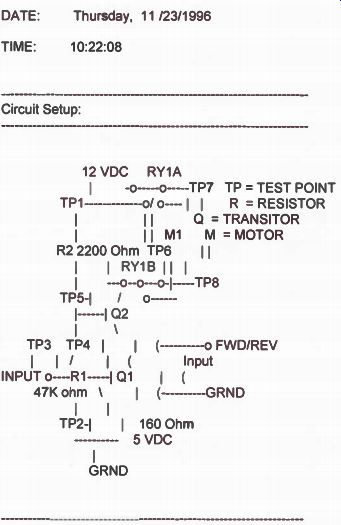
Once a file is open you may see information similar to that shown in the figure on the following page. This file contains a wealth of information including:
1. The Problem name and Fault number.
2. A statement of what the fault was. For example: The problem was: Resistor R1 is open.
3. Date and time that the problem was started.
4. A simple circuit representation to refresh your memory (if needed) of the schematic diagram.
5. Under the heading "Recordings," the step by step procedure that you performed. The number of steps may be lengthy and require you to move to the next page to see all of the recorded actions taken.
6. Each step indicates the time the step occurred in minutes and seconds.
7. Each step indicates the procedure performed and its outcome.
Factors to Consider
As you progress through the CAT program, every step of your performance is captured on the student workdisk.
By carefully analyzing the "trail" that you have followed, you can accurately evaluate your performance through the various troubleshooting scenarios.
However, troubleshooting is as much an art as it is a science. Keep in mind that it is your technique you will be judging as well as the final result. Because of trouble shooting's very nature, evaluating one's performance is somewhat subjective. No two technicians will approach troubleshooting in exactly the same way. And while there are general guidelines, it is difficult to list specific rules that are right for every situation. Indeed, troubleshooting philosophy varies widely from one company to the next, and you will even find diverse views among experienced technicians. Consequently, as a student, you will have to make many judgment calls as to how you carry out the troubleshooting assignment. Even so, the following guidelines will be of some use to you in evaluating your performance.
-----------
Direct-Coupled DC Amplifier
CIRCUITS TROUBLESHOOTING
Direct-Coupled DC Amplifier Fault # 1
------
Recordings:
| 0:08| The technician took a reading on TP1,TP5 -- Infinite ohms
|0:12| Technician replaced RESISTOR 2 with a new one
|0:15| The technician checked the result and got a right answer
-----------
There are several factors you should consider in evaluating your performance. These include:
1. Did you find the fault and fix it? This is the most fundamental question to ask. After all, this was the assignment. Failing repeatedly in this task indicates that you do not fully understand the assignment, or how the program works, or you may have serious deficiencies in your knowledge of the subject.
Even so, this is not an unusual situation the first or second time that you are exposed to the program. Usually it indicates that you are not yet comfortable with the pro gram. Examining one's actions as recorded on the work disk should go a long way toward pointing out your weak areas.
2. Did you approach the problem in a logical way? This is perhaps the single hardest question to answer.
Normally, you will be expected to make voltage or resistance measurements prior to replacing a component. Did you do this in a systematic way, making all voltage measurements before moving on to resistance measurements or vice versa? Did you make enough measurements and the right types of measurements to uniquely identify the fault? Did you make far more measurements than were necessary?
3. Did you use the equipment properly? Did you attempt to measure voltage with the power off? A minor infraction. Or did you attempt to measure resistance with the power on? A more serious offense.
4. Did you follow good safety practices? Did you attempt to remove a component with the power applied?
5. How many components did you replace before fixing the problem? Ideally you should replace only the malfunctioning component. Wholesale replacement of parts will eventually result in a "fix" but is not considered good practice.
6. How long did it take you? By reading the Tb file(s) on the student workdisk, you can determine the exact amount of time spent on each step of the troubleshooting scenario as well as the over all problem. You may want to take this into consideration. Time can play a crucial factor in troubleshooting when customers and their money is involved.
As the student, it is your responsibility to decide how much weight will be placed on each of the above factors and any other factors you may consider important. Also, you may want to change the weight of some factors as you progress. For example, forgetting to shut off the power before working on the circuit might be attributable to unfamiliarity with the program the first time it happens. But, it might be judged more severely on subsequent occurrences.
Additional Ways to Use the Program
Once you become proficient at finding and repairing the faults using your own individually developed techniques, some additional variety can be introduced by setting up special scenarios which will cause you to rethink their techniques. For example, you may want to run through the program under one of the following scenarios:
1. Find and fix the fault as quickly as possible. There are situations in which time to repair is the most important factor. A failure of a key piece of equipment on an assembly line comes to mind. Every second that the line is down costs the company money. When time is the overriding concern, the troubleshooting technique may be radically different.
2. Find and fix the fault with minimum soldering. Soldering is an intrusive procedure. Anytime you remove or replace a component by soldering you risk damage to adjacent components, the circuit board, or the component being removed. This is especially true with today's micro miniaturized electronics devices and multilayer circuit boards.
3. Find and fix the fault making measurements only with the voltmeter. Limiting the use of test equipment to the voltmeter will cause you to use Ohm's Law and other theoretical concepts. So while this may not be a legitimate technique, it makes an interesting learning experience.
------------
The Problems
The Problems and Faults were chosen to give the student a cross section of troubleshooting experience. The early scenarios are designed to ease the student into trouble shooting while the later ones provide a more thought provoking challenge. There are no trick problems although in the last two problems component values and the characteristic of the meter are selected to prompt discussion. All malfunctions are either open or shorted components. There is only one malfunction per fault.
Objectives of the Program
Upon completion of this exercise you will be able to:
1. Use a schematic diagram and a component view of a circuit, match each component and test point on the schematic with its counterpart on the circuit board.
2. Demonstrate that widely separated points on a circuit board may be "electrically" identical.
3. Demonstrate the proper use of a voltmeter and ohmmeter.
4. Use a series circuit with an open component, find and replace the faulty part.
5. Use a series circuit with a shorted component, find and replace the faulty part.
6. Use a series-parallel circuit with an open component, find and replace the faulty part.
7. Use a series-parallel circuit with a shorted component, find and replace the faulty part.
8. Use a bridge circuit with an open component, find and re place the faulty part.
9. Use a bridge circuit with a shorted component, find and replace the faulty part.
10. Demonstrate the proper method of testing a switch with an ohmmeter.
11. Demonstrate the proper method of testing a capacitor with an ohmmeter.
12. Demonstrate that the resistance value measured across a component connected in a circuit may be vastly different from the value measured across the same component removed from the circuit.
13. Demonstrate that power should be removed from the circuit before any repair is attempted.
14. Demonstrate that power should be removed from the circuit before using the Ohmmeter.
15. Demonstrate that because of component and meter tolerances, resistance and voltage measurements are not always exactly what the student expects.
16. Demonstrate the value of being able to estimate what voltage or resistance reading to expect.
17. Demonstrate the unique abnormalities caused in various types of circuits by opens and shorts.
Series Resistors
This first problem is designed to get the student comfort able with using the CAT program. The resistance readings match the color codes exactly and the voltages are about what you would expect from Ohm's Law. The resistance values make it easy for the student to estimate what the voltages should be. The faults introduce a variety of shorts and opens, with symptoms that are easy to spot.
Series/Parallel Resistors
In this problem, the student begins to experience tolerances but still not enough to confuse the outcome. The resistance readings begin to diverge slightly from the "ideal." Here again, resistor and voltage values are such that estimations are fairly easy. The four faults that are introduced will give the student an excellent grasp of the unique characteristics of shorts and opens in the series/ parallel combination.
Resistor Bridge
In this problem, the concept of "tolerances" is driven home. Some of the resistance readings are deliberately chosen to cause the student to think about component and meter tolerances. By the time you complete all four faults, you should begin to realize that the readings obtained in the real world may vary from the ideal values predicted by theory alone.
A/C Combination
In this final problem, three additional types of components are introduced: the capacitor, the switch, and the lamp. Also the added feature of being able to open and close the switch, both in and out of the circuit, adds variety, realism, and interest for the student. Here again, component values and the characteristics of the meter are chosen to make the student think. In particular, the value of the capacitor is small enough so that its charge and discharge are hidden by the initial blanking of the meter. Also, when power is removed, the capacitor quickly discharges back through the power supply load resistance (not shown).
------------
Answer Sheet
DC Electronics Troubleshooting
Series Resistors Fault #1
Control Panel Lights R1 open Fault #2
Control Panel Lights R3 shorted Fault #3
Control Panel Lights R3 open Fault #
Control Panel Lights R2 shorted Series/Parallel Resistors Fault #1
Snowmobile R2 open Fault #2
Snowmobile R3 open Fault #3
Snowmobile R1 shorted Fault #4
Snowmobile R1 open Resistor Bridge Fault #1
Bridge Circuit R2 open Fault #2
Bridge Circuit R4 open Fault #3
Bridge Circuit R3 shorted Fault #4
Bridge Circuit R1 shorted R/C Combination Fault #1
Test Equipment R1 open Fault #2
Test Equipment L1 open Fault #3
Test Equipment C1 shorted Fault #4
Test Equipment C1 open
---------------
Graduates Say... "I would highly recommend anyone to give NRI a try The lessons are easy to understand and are set up in a way that makes them easy to remember. The reason I chose NRI is because I was recovering from a back injury and surgery and it seemed like a great way to pass the time.
The money I have made as a result of NRI has more than paid for what the course cost me. In fact, I plan on enrolling in another course in the future."
-Jeffrey Mallm Lockport, New York
---------------------------