
AMAZON multi-meters discounts AMAZON oscilloscope discounts
Shunt reactors
Shunt reactor compensation is usually required under conditions that are the opposite of those requiring shunt capacitor compensation.
Shunt reactors may be installed in the following conditions:
• To compensate for overvoltages occurring at substations served by long lines during low-load periods, as a result of the line's capacitance (Ferranti effect as voltage tip up)
• To compensate for leading power factors at generating plants, resulting in lower transient and steady-state stability limits
• To reduce open-circuit line charging kVA requirements in extra high-voltage (EHV) systems.
The effect of shunt reactance on the current phasor diagram.
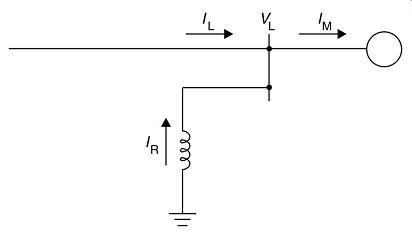
FIG. 7 Shunt reactor compensation
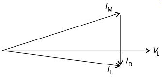
FIG. 8 Effect of shunt reactors
Synchronous compensators
A synchronous compensator is a synchronous motor running without a mechanical load.
AMAZON multi-meters discounts AMAZON oscilloscope discountsIt can absorb or generate reactive power, depending on the level of excitation. When used with a voltage regulator, the motor can run automatically over-excited at high-load current and under-excited at low-load current. The cost of installation of synchronous compensators is high compared to capacitors, and the electrical losses are considerable relative to capacitors.
Why would the losses of a synchronous motor, utilized as a reactive compensator, be high compared to capacitors? Synchronous condensers can also be used as dip mitigation devices to support the voltage during drops.
Static VAR compensators
Static VAR compensators (SVCs) contain shunt capacitors and reactors, which are controlled by thyristors. They provide solutions to two types of compensation problems normally encountered in practical power systems:
• The first is load compensation, where the requirements usually are to reduce the reactive power demand of large and fluctuating industrial loads, and to balance the real power drawn from the supply lines.
• The second type of compensation is related to voltage support of transmission lines at a certain point in response to disturbances of both load and generation.
The main objectives of dynamic VAR compensation are to increase the stability limit of the power system, to decrease voltage fluctuations during load variations and to limit overvoltages due to large disturbances.
The two fundamental thyristor-controlled reactive power device configurations are:
1. Thyristor-switched shunt capacitors: The capacitor bank is split into small capacitor steps and those steps are switched on and off individually. It offers stepwise control, virtually no transients and very little harmonic generation.
The average delay for executing a command from the regulator is half a cycle.
2. Thyristor-switched shunt reactors: The fundamental frequency current component through the reactor is controlled by delaying the closing of the thyristor switch with respect to the natural zero crossings of the current. Harmonic currents are generated from the phase-angle-controlled reactor. There are two methods to reduce the magnitude of the generated harmonics. The first method consists of splitting the reactor into smaller steps, with only one thyristor-controlled step while the other reactor steps are either on or off. The second method involves the 12-pulse arrangement, where two identically connected thyristor-controlled reactors are used, one operated from wye-connected secondary winding, and the other from a delta-connected winding of a step-up transformer. Thyristor-switched reactors are characterized by continuous control, and there is a maximum of one half-cycle delay for executing a command from the regulator.
AMAZON multi-meters discounts AMAZON oscilloscope discountsIn many practical applications, a combination of these two thyristor-controlled devices are used, with the SVC consisting of a few steps of thyristor-controlled capacitance and one or two thyristor-controlled reactors.
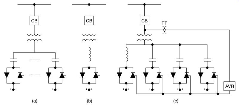
FIG. 9 Basic static VAR compensator configurations
It’s important to note that applying static VAR compensators to series-compensated AC transmission lines results in three distinct resonant modes:
1. Shunt capacitance resonance involves energy exchange between the shunt capacitance (line charging plus any power factor correction and SVCs) and the series inductance of the lines and the generator.
2. Series-line resonance involves energy exchange between the series capacitor and the series inductance of the lines, transformers and generators.
3. Shunt-reactor resonance involves energy exchange between shunt reactors at the intermediate substations of the line and the series capacitors.
Due to the above, it’s crucial to represent any compensators in transient electrical simulation programs.
Distribution applications -- shunt capacitors
Shunt capacitors are used more frequently in power distribution systems than any other electrical compensation device. They are used mostly for voltage regulation and power factor correction; hence, these two specific applications will be briefly discussed.
above: High Voltage Shunt CapacitorVoltage regulation:
Voltage drop can be reduced by the application of a shunt capacitor. A correct selected and located shunt capacitor assures that the voltage at the load will be within the allowable limit at the heavy load condition. However, at light loading, the same capacitor will increase the voltage to above the allowable limit.
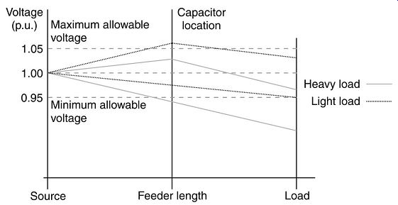
FIG. 10 Capacitor effect on voltage.
The way to avoid this is to use switched capacitor banks. The capacitors are switched in during heavy load conditions and switched out during light load conditions. When the capacitor(s) is switched in, the capacitive current is added to the inductive current, reducing total current, voltage drop and electrical losses. The last is due to reducing reactive power in the system (see next paragraph). The optimum number, size and location of capacitor banks on a feeder are determined by detailed computer analysis, also taking into consideration minimization of the operation, installation and investment costs. The most important factors that affects the selection is the voltage levels, total loading, distribution factor and power factor of loads.

Power and power factor:
Power in a three-phase distribution system consisting of two components, namely active or real power (P) and reactive power (Q). The complex sum of the two gives apparent power (S). Hence, S = P + jQ. This is shown in the well-known power triangle.
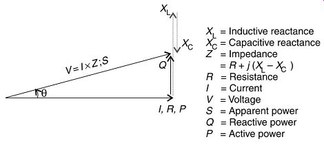
FIG. 11 Power triangle.
Apparent power (S) in a three-phase system is calculated by the formula, S = v3VI. This is expressed in VA, kVA or MVA, and is the unit used for the ratings of transformers.
Power cables and transformers add reactance to a power network, which is mainly inductive (a lesser amount of capacitance is also added). The inductive and capacitive reactances are frequency dependent (hence are only present in AC systems), oppose each other and are at right angles to the pure (dc) resistance. The net reactance, which is usually inductive, opposes the flow of current, and the power required to overcome this reactance is called reactive power (Q). This is wasted power, which is of no benefit to the user. Reactive power is calculated by the formula, Q = v3Visin f, and is expressed in VAr, kVAr or MVAr.
The presence of reactance in the network causes the voltage and the current phasors at the load to move out of phase by the phase angle f . (The voltage phasor is taken as the reference, and the current phasor is then defined as 'lagging' with respect to a counter clockwise phase rotation.) The cosine of the phase angle (cos f) is known as the power factor.
The longer the cables and the more transformers in a distribution network, the more inductive reactance is present in the network, the greater the phase angle (lower power factor) and the higher the losses. Adding capacitance to an inductive network will serve to decrease the phase angle (f), improve the power factor (cos f) and result in a more efficient distribution network. This is known as power factor correction.
When more capacitive than inductive reactance is present in the network, a leading phase angle may result, with the current phasor leading the voltage phasor. A leading phase angle will have detrimental effects on the operation of induction motors, and must be avoided.
Active power is the electrical power available to be utilized usefully, and is expressed in W, kW or MW. This is the unit in which electric motors, lights, heaters, etc. are rated.
Active power is expressed by the formula ...
Causes and effects:
Any equipment with inductive properties will worsen the power factor, as reactive power is used to overcome the inductive reactance. Therefore, induction motors, transformers and cables will all add to increase f. In addition, variable speed drives that use waveform 'chopping' will also worsen the power factor due to the distortion of the current waveforms, in addition to adding harmonics to the system. The effect of a low-power factor at the load is that more current is required to achieve the same power output, as can be seen from the power formulae. The following is an example of the effect of low-power factor:
Required active power: 200 kW; Operating voltage: 415V; Case 1: = 0.85
It can be seen from the above example that power factor has a substantial effect on the magnitude of current flowing in the network. A sustained low-power factor may have the following effects:
• Overheating of equipment due to the excess current flowing
• Equipment being over-rated to compensate for higher currents flowing due to low-power factor
• Higher electricity consumption when measured in VA
• Necessitate additional investment in system facilities to obtain the required kW
• Lower voltage level at the load
• Increased power losses (resistive and reactive) throughout the system due to higher currents flowing.
Tariff example:
Many countries' electricity utilities introduced a penalty charge for customers with low power factor. Several countries have changed from a kW tariff to a kVA tariff for maximum demand. A low-power factor will have a direct influence on the amount of total kVA a company will use to obtain a certain amount of active kW power (kVA = kW + jkVAr [complex values]). The lower the power factor the more VARs are consumed.
Therefore, a low-power factor (pf) will result in inefficient energy usage and an excessive energy bill. Some utilities penalize consumers if their pf is below 0.96 and others if below 0.80. The client is then billed for a kVA maximum demand instead of a kW maximum demand.
Let us look at an example:
To simplify the calculation for illustration purposes, we assume average values.
A factory's average monthly maximum demand is 100 MW at a power factor of 0.65.
The power triangle for this situation is shown. For a power factor of 0.65 and real power (P) of 100 MW, the apparent power (S) is 153.846 MVA and reactive power (Q) is 116.913 MVAR [P = S cos f; Q = S sin f]. As can be noted, the reactive power in the network is of a higher value than the real power!
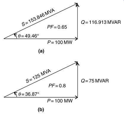
FIG. 12 Example power triangle.
The power factor needs to be higher than what value for the reactive power to be less than the real (active) power--- Referring to ---, to increase the power factor to 0.8 would need 41 913 kVAR. Therefore, the factory would be charged $0.38 * 30 * 42 = $478.8 over a month period, which could be avoided by increasing the power factor to 0.8! This should be more than enough economic justification to install power factor correction (PFC) equipment.
As a very rough approximation, the capital investment for PFC equipment can be taken as $250/kVAR on 11 kV. Therefore, to add -42 MVAR capacitive would mean a capital investment of $10.5 million, which would be paid back in approximately 22 months.
Approving power factor also have added benefits, like reduced active and reactive losses due to the reduction in the magnitude of currents flowing.
| Top of Page | PREV: Compensation--part 1 | NEXT: Caution: effect of shunt capacitors on induction motors | Index |