AMAZON multi-meters discounts AMAZON oscilloscope discounts
This section focuses on the basics of lightning phenomenon, switching surges and typical mitigation techniques.
Earth (ground) current transients
In FIG. , looking at the comparison between atmospheric transients and ground current transients, we are reminded that, if it were possible, it would do us a lot of good to be in the open air, above ground, rather than to be in the ground itself. We would much rather take our chances with a varying electrostatic field and the results that occur in an insulating medium, the air, rather than take our chances with what is taking place in a conducting medium, namely, the ground. In days gone by, we were able to suspend our telephone and data lines under-built below a power line. We were even able to hang our inter-plant lines in open air and the risk was much less from the direct strikes or the effects of the electrostatic field than it’s when we go into the ground. We might have induced transients come to us as lines are close to each other in the construction process of under-building and overbuilding, but again, the end-result effects were considerably less.
AMAZON multi-meters discounts AMAZON oscilloscope discounts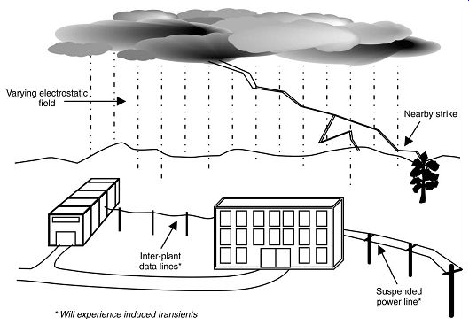
FIG. 13. Atmospheric transients
Consider FIG. now, where placing all of our lines in the ground, we tend to no longer use the old-fashioned construction methods. The older methods consisted of bearing a piece of steel conduit in a concrete encasement and then placing wires in the center. In that construction, the metallic wires were protected, at least in part, by the shielding effect of the steel conduit. The conduit, in turn, was protected from deterioration in contact with the soil by being encased with concrete. With today's modern technology, most of the under ground installations are performed with PVC conduit with very little protection for the electromagnetic properties of the noise transients running in the ground. We can see the impact of ground current transients running back and forth and perhaps intercepting the conductors running in the plastic conduit buried between the buildings. If there were direct lightning strikes to the ground or if a power line with a lightning arrestor was discharging its energy into the ground, then the PVC conduit with wires might be intercepted and the metallic wires would carry these transient charges in both directions.
AMAZON multi-meters discounts AMAZON oscilloscope discounts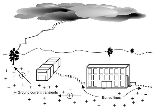
FIG. 14. ground current transients.
The one exception to this, of course, is glass fiber installations which do not, of themselves, conduct any of these ground transients when buried in the ground directly.
Transient impact:
In FIG. we see the impact of a transient phenomenon making for high field strength and dielectric stress as well as a very high rate of change of voltage with regard to time, producing a high current component. Just a reminder to us: transient phenomena can be very dangerous.
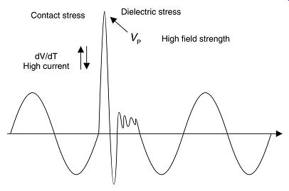
FIG. 15. Impact of a transient.
Lightning phenomenon:
Let us begin by talking about what happens when a lightning strike hits an overhead distribution line. Here we see the picture of the thunderstorm cloud discharging onto the distribution line and the points of application of a lightning arrestor by the power company at points 1 and 2. We notice that the operating voltage here is 11,000 V on the primary line and the transformer has a secondary voltage of 400 V typically serving the consumer. We need to understand what is known as traveling wave phenomenon. When the lightning strike hits the power line, the power line's inherent construction makes it able to withstand as much as 95,000 V for its insulation system. We call this the basic impulse level (BIL). Most of the 11,000 V construction equipment would have a BIL rating of 95 kV. This says to us that the wire insulation, the cross arms and all of the other parts which are nearby the current-carrying conductors are able to withstand this high transient voltage.
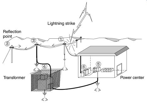
FIG. 16. Lightning strike to an overhead distribution line.
When an overhead line is struck by lightning, an overvoltage surge travels down the line. The magnitude of the voltage pulse is determined by the current of the lightning volt and the surge impedance. Upon reacting a surge arrestor the overvoltage will be limited to the clipping voltage of the range arrestor, say 45 kV for an 11 kV system. At the transition from the overhead line to a cable, transformer or at the end of the overhead line the traveling wave will be reflected and the voltage doubled by super position. It’s therefore important to install surge arrestors at all transition points in a power system.
Where do we place an arrestor?
FIG. poses some serious questions. Where do we put a lightning arrestor? Do we need one at all? What is it you wish to blow up? The computer? The UPS? Or perhaps you would like to save all of that sensitive equipment. It may be a humorous type of description, but the practical, real world finds many people placing lightning arrestors and discharge devices inside of occupied spaces where the equipment and the personnel represent a heavy financial burden as well as a safety factor. Most safety standards will advise that discharge devices don’t need to be located where there are either personnel or equipment to be protected. The location of a discharge device, such as a lightning arrestor, is to be at the large service entrance ground, where the electric utility makes its service connection to the premises. Here, at this point, this discharge device which has large levels of current, then has a sufficiently large ground plane into which to discharge that current without a damaging effect on sensitive equipment. Typical lightning arrestor ratings call for 65000 A of discharge capacity for distribution class arrestors, 100000 A of discharge capacity for station class arrestors, and even at the 600 V and below level, 40000 A of capability at the minimum. So we notice that these questions are not silly, but they do point out that we need to locate our lightning arrestor product as close to the service entrance as possible.
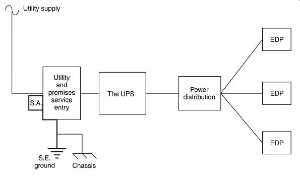
FIG. 17. Positioning of a lightning arrestor
Arrestor and supplementary protection:
From the Federal Information Processing Standards we have a picture of the combined placement of lightning arrestor products and surge protection devices called transient surge protectors. Notice that the writers of this document were very accurate in the location of the arrestor product and to make it as close to the power source as possible. In addition, they give us a picture of the use of the older style arresting products, which required capacitors to affect wavefront modification. Let us explain that. Wavefront modification means that the voltage rise is so fast that if something does not mitigate that rise, the wiring may be bridged by the extremely high voltage in the surge. Downstream from the arrestor location, over a certain amount of distance, preferably greater than 10-15 m (30-50 ft), if possible, should be the second level of protection as a transient surge protector. This device, indicated as combination suppresser and filter package made up of a variety of different types of components which will now protect against the residual energy that is flowing in the circuit. The structure that we see here is one in which the various components installed in the system, starting at the service entrance, then to a sub-panel and then, finally, to discrete individual protectors, will now attenuate more and more of the surge energy until it’s completely dissipated.
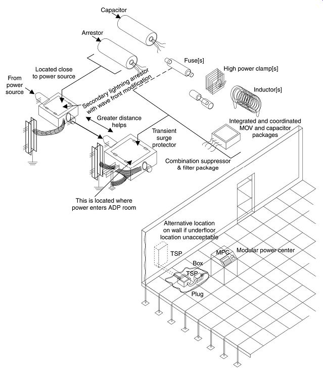
FIG. 18. Supplementary surge protection elements
Transient clipping:
We see the onrushing surge coming into a transient voltage surge suppression device (TVSS), now becoming better known as surge protection device (SPD), and having its upper portion limited or chopped before it comes to the load. The surge protection element actually is taking off or limiting that high-transient phenomenon and sending it back into the ground path where it will do very little harm.
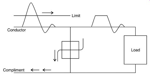
FIG. 19. Onrushing surge
Protection locations:
FIG. consists of a series of diagrams demonstrating the overall electric utility supply and internal wiring. We see the recommendation that is consistent with what we have been talking about before. The black boxes marked on our drawing as SPDs first appear connected at the service entrance equipment inside the building where it receives power from the service transformer. Next we see an SPD device at a panel board or sub panel assembly. Finally, we may find a lower voltage style device as a discrete device either plugged in at an outlet or perhaps approaching the mounting of this device within a particular piece of sensitive equipment itself.
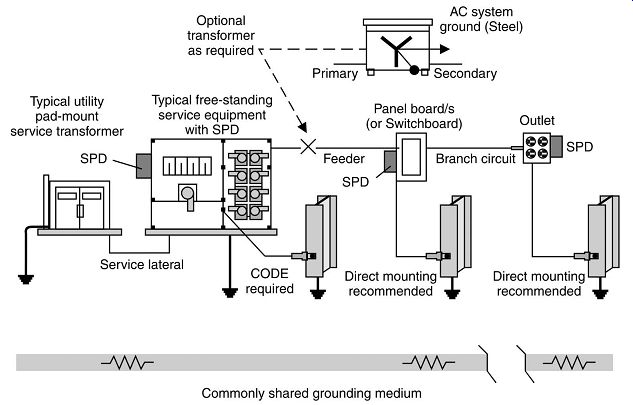
FIG. 20. Typical location of power distribution TVSS/SPD
Protection zones:
We call this the zoned protection approach and we see these various zones outlined with the appropriate reduction in the order of magnitude of the surge current as we go down further and further into the zones, into the facility itself. Notice that in the uncontrolled environment outside of our building we would consider the amplitude of say, 1000 A. As we move into the first level of controlled environment, called zone 1, we would get a reduction by a factor of 10 to possibly 100 A of surge capability. As we move into a more specific location, zone 2, perhaps a computer room or where the various sensitive hardware exist, we find another reduction by a factor of 10. Finally, in the equipment itself, we may find another reduction by a factor of 10 of the effect of all of this surge being basically 1 A at the device itself.
The idea of the zone protection approach is to utilize the inductive capacity of the facility, namely the wiring, to help attenuate the surge current magnitude as we go further and further away from the service entrance to the facility.
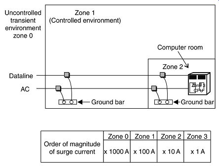
FIG. 21. Zoned protection approach
Service entrance zone:
Here we have a detailed picture of the entrance into the building where both the telecommunications, data communications and the power all enter from the outside to the first protected zone. Notice that SPD is basically stripping any transient phenomena on any of these metallic wires, referencing all of this to the common service entrance ground even as it’s attached to the metallic water piping system.
Discrete device zone:
Here as we address the discrete level between the first level of controlled zone 1 and perhaps the plug-in device taking it into the zone 2 location, we can see SPDs are available that handle the telecommunications, data and different types of physical plug connections for each, including both the RJ type of telephone plug as well as coaxial wiring.
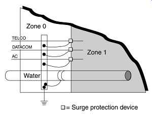
FIG. 22. Zone 0 protection
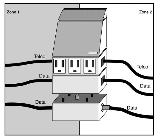
FIG. 23. Zones 1 and 2
This is a common design error where two points of entry and therefore two grounding points are established for the AC power and telecommunications circuits. The use of SPDs at each point is highly beneficial in controlling the line-to-line and line-to-earth surge conditions at each point of entry, but the arrangement cannot perform this task between points of entry. This is of paramount importance since the victim equipment is connected between the two points. Hence, a common-mode surge current will be driven through the victim equipment between the two circuits despite the presence of the much needed SPDs. The minimal result of the above is corruption of the data and maximally, there may be fire and shock hazard involved at the equipment.
No matter what kind of SPD is used in the above arrangement nor how many and what kind of additional individual, dedicated grounding wires, etc. are used, the stated problem will remain much as discussed above. Wires all possess self-inductance and because of -e = L di/dt conditions, cannot equalize potential across themselves under normal impulse/surge conditions. Such wires may self-resonate in quarter-waves and odd-multiples thereof, and this is also harmful. This also applies to metal pipes, steel beams, etc. grounding to these nearby items may be needed to avoid lightning side-flash, however.
Adding more grounds to the above (such as at the victim equipment) is not effective since these merely act as taps into the voltage-current divider that the ground represents due to its ohms/unit value at any given frequency. This value gives up with increased frequency. Therefore, such taps just create more loops for the surge currents to flow and ring back-and-forth in. These connections cannot be implemented in any case when the equipment is located on floors above ground. Therefore, schemes based upon such connections would fall in any case due to the need to place equipment anywhere in a building and on any floor, etc. and the 'long' wires necessitated to be used to reach 'earth' floors away.
While the shown SPDs are highly beneficial (from normal-mode surge), some additional improvements must be made to cope with common-mode problems (such as lightning!).
Site overview:
We’re fortunate to have from consulting associate, Mr Servis, an excellent overview of how to prepare the power, telecommunications, grounding and surge current routing for protection. In our first view, we see the typical victim equipment being caught in between surge impulses coming from the service entrance of electrical power as well as coming through the entrance of the telecommunications product.
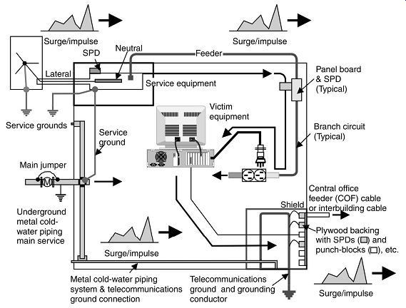
FIG. 24. Overview of a typical site: Power and telecommunications grounding
and surge current routing through victim equipment
Otherwise unchanged from the previous drawing, the recommended usage and location of a combination data and AC SPD unit employed for protection of the equipment connected between the AC and telecommunications systems. This practice is easy to implement on a case-by-case basis, but it’s not a complete solution since the beneficial effects of the arrangement are not complete. In other words, there is always a residual surge current to deal with due to Kirchkoff's current law being operative at the junctions within the AC and data SPD unit. No SPD vendor can eliminate these phenomena.
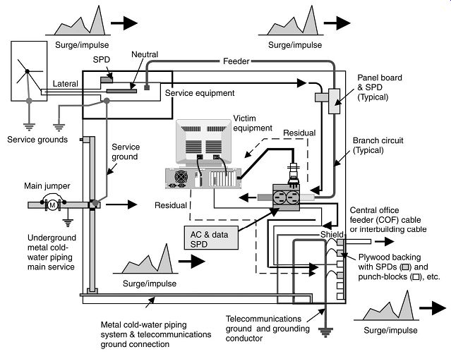
FIG. 25. Improved protection of victim equipment connected between AC power
and telecommunications circuits (localized SPD protection).
The SPD located at the service entry is beneficial in that it diverts some of the current that would otherwise enter the victim equipment's susceptibility path. The same holds true for the SPD at the telecommunications entry area. Both are important to have.
The shown solution is still flawed since the surge current is still allowed to flow largely within the facility and on the AC and telecommunications wiring. This means lots of stray coupling into other circuits along the way, and in some cases, localized arcing between items that are conductive and at different potentials. The locally installed SPD at the AC and telecommunications ports for the shown 'Victim Equipment' cannot have any practical effect on these unwanted phenomena. Therefore, something further must be done to improve matters to the level consistent with the demands of a modern, commercial establishment utilizing electronic computer/data processing and telecommunications systems that are interconnected.
Specialized 'earth' grounding at the local SPD point is not generally required of beneficial, in fact, adding another 'earth' into the circuit at this point might be an additional surge current injection point! Local connection to local building steel, etc. are always a good practice, but not a requirement.
Improved protection:
The improvement in protection for the victim equipment is shown where the protected devices are located at the incoming power, a sub-panel board and the victim equipment itself.
Typically for new construction, the telecommunications cables and the AC power need to be brought into the facility at essentially the same point so that the two may be literally locked-together from an grounding/bonding and SPD standpoint. This must be done using high-frequency techniques. Surge currents are impulses and are therefore high-frequency currents. As a result, wiring practices intended to motivate the unwanted effects of such surge currents must reflect this high-frequency characteristic in the implementations of the grounding and SPD practices. The techniques must also conform to the requirements of the Electrical Code (NEC) as do those shown above.
The goal is to minimize the potential difference between the telecommunications and AC power systems, not necessarily of either system to ground. The problem is the exchange of surge current between these two systems under common-mode current conditions, and through victim electronic equipment, that interconnects the two systems from a surge current standpoint.
Earth (ground) is a valuable reference for common-mode surge current (such as lightning), but the only time that ground can be used is when the connection being made to it’s physically short and low-inductance (both!). Therefore, connections intended to divert current in/out of the ground must be physically close to the equipment and the ground point itself or:
-e = L di/dt,
simple impedance, and resonance effects in the path will defeat its effectiveness. This cannot be accomplished on floors above ground due to the length of the grounding/bonding conductors needed to effect the connection. Hence, the protection scheme employed must only use the ground connection at ground level - it’s not effective anywhere else in the building (such as on the 25th floor!). Therefore, all initial attacks on surge current take two forms: ground ground diversion of common-mode surge current at ground level plus voltage clamping between the AC and telecommunications systems (must be done in all possible modes). This is best done at the common point of entry for both systems to the facility. Then, secondary and tertiary attachments on the common-mode surge current to a place whenever the two systems (ac power and telecommunications) can be physically brought together and SPD interconnected in low-inductance fashion. Normal-mode protection on the AC system and the telecommunications system is generally effective wherever it’s done in a path via the simple addition of a suitable SPD, since 'earth ground' is not a part of this process.
Recommended practice -- joint entrance:
Here in our sequence we find the recommended practice for installation of power and telecommunications entrances, typically, for new construction.
Two major changes are made in this figure to greatly reduce the surge current problem between the AC power and telecommunications circuit. The first is to disconnect the COAX cable from its landings on the plywood board and to reroute its end (including the gas-tube SPD assembly on it) into a metal pull-box. The cable's shields and the SPD are well-bonded to the metal box, which in turn is connected to a newly installed, driven earth-ground installed just below the pull-box (this keeps wires short).
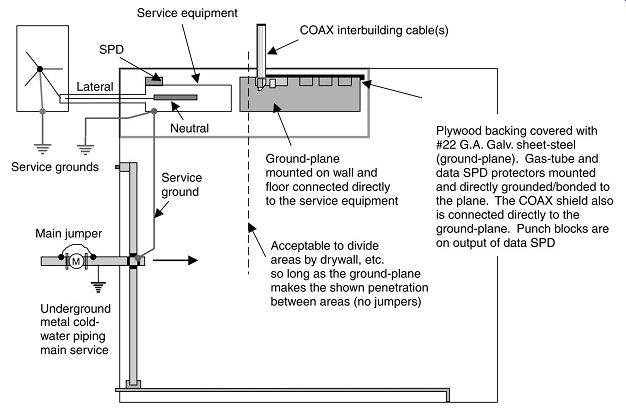
FIG. 26. Recommended practice for installation of AC power and telecommunication
lines on a facility (with SPD protection)
The second change is to reroute the COAX cable from the pull-box via ferrous metal conduit, to the service equipment area where it’s landed to a high-quality SPD (i.e. a 'data protector') that is in turn grounded/bonded to the service equipment via a wall and floor mounted ground-plane. This is a #22 gage, galvanized steel arrangement that is secured to the wall, run down to the floor, bent at 90° and run to the service equipment, where it’s lineally bonded to that equipment (weld, braze, solder or several screws, in that order or desirability). All COAX cable conduit is grounded/bonded to this ground-plane on both sides.
Next, the COAX cable is returned to the telecommunications area via another ferrous metal conduit as shown. Once the return is made the various pairs are landed to whatever punch-block terminals that they would have originally gone to.
The ferrous metal conduit used above is most effective if it’s rigid conduit, then intermediate conduit, and finally, 'thinwall' (EMT) conduit. Don’t use flexible conduits of any kind. Aluminum is acceptable, but steel is best. Also, don’t make any effort to 'insulate' these conduits along the runs. Just install them in 'normal' fashion. In fact, the conduit is meant to connect multiple points of 'earth', the one at the service lateral (the power supply ground) and the other 'signal ground' at the communication entry point, into a single equipotential reference plane. When joining circuits or terminating them, use high quality fittings and connectors. The best type is threaded, then circumferential compression ring types, and lastly, the set-screw types.
The service and telecommunications systems are SPD 'surge-locked together' in this arrangement.
Retrofitting recommendations
Here we find a recommendation for the retrofitting of a telecommunications and power system for improving the lightning and surge immunity. You’ll notice that the heart of this is to correct the facility where a separate telecommunications entrance had been made and to bring ferrous conduit carrying the telecommunications cable main runs over to the service entrance ground-plane for the electric power and then return it back to its plywood backing and punch-block location at the separate telecommunications entrance. While this seems to be somewhat of a redundant method for doing these things, it works very well in terms of providing additional protection.
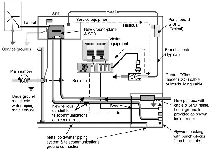
FIG. 27. Retrofitting a telecommunication and AC power system for improved
lightning and surge immunity (Recommended).
Still further improvement in surge protection is obtained once additional protection for the victim equipment is added at the local point where the equipment is installed. This is generally accomplished via the use of a combination AC and data SPD as shown and as previously discussed.
In the shown arrangement above, there is only 'residual' surge current to be controlled by the locally applied AC and data SPD as opposed to its being required to handle principal surge currents. This means that the locally applied protection becomes very much more effective since it’s now acting as a second (and sometimes third) stage of surge current diversion and voltage clamping point. Less surge current is input to the local protection by the above arrangement so less escapes its effects to finally reach the victim equipment. However, something will always reach the victim equipment since no protection scheme is 'perfect'. But, if what does reach it, stays well below the point of component damage, the equipment will be 'protected' in all but the most extreme cases.
This arrangement is a form of a 'cascade' protection scheme. The idea is to progressively divert surge currents at each level - nearest the point of entry, then downstream, and finally at the victim equipment itself. At each level of protection, destructive energy is taken out of the surge, its current and voltage level is reduced, and its waveshape is also rendered less likely to have fast transitions which are the principal cause of -e = L di/dt problems in the current's path.
Note that the original 'Telephone Company' protector (the gas-tube SPD) that is installed on the end of the COAX cable is retained and is locally grounded/bonded to both the metal equipment conduit/raceway system and to a local earth grounding electrode system. This maintains the 'Bell System' requirements for the installation and also permits a 'first line of defense' to be provided at the point of entry for the COAX to the building. This cable-end SPD may do a lot of good and can relieve the SPD installed at the service from having to handle the highest levels of surge currents that might enter via the telecommunications cable, etc. However, this does not mean that the 'data' SPDs installed at the service don’t have to be 'heavy duty', they do. Surges arriving on the AC service will trigger these SPDs, and so they must handle the large amounts of current that this implies.
Adding local protection
Hence, in summary, to the routing of the telecommunications cable in ferrous conduit, we will add, as we have seen before, the local power, sub-panel and discrete surge protection devices to improve the immunity of the product.
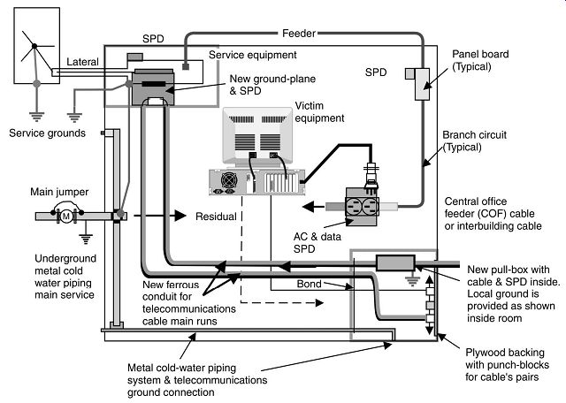
FIG. 28. Adding local AC and data SPD protection for improved lightning
and surge immunity (Recommended).
The ground-plane is now shown fully developed and covering both the wall(s) and the floor in the telecommunications equipment area. The whole area need not be covered by the ground-plane, just as shown/needed. Also, the AC power is now integrated with the same high-frequency ground system that the telecommunications system is using and all SPDs are commonly referenced to it as well.
The separately derived AC system needs to be solidly grounded as shown from one or more of the chosen AC system grounding electrodes (A, B or C). The preference is structural building steel, the made electrode system and then the metal cold-water piping, all in order of desirability. Best results are obtained when two or more of the shown electrodes are available to the ground-plane, although only one needs to be connected directly to the transformer for AC system grounding.
Cable trays/ladders must be electrically continuous so ends must be grounding/bonding jumpered together when two more sections meet or approach across a gap or other space.
This is especially important to do when the tray/ladder penetrates walls, etc. Continuation of the cable into the site without tray/ladder is best done within ferrous metal conduit/raceway with it well grounded/bonded to the tray/ladder at the point of conversion.
Clamps, welds, brazing and direct soldering are all methods employed to connect items together instead of inductive means such as long grounding/bonding wires, etc. Such wires may be added to what is shown so as to allow the installer to 'see' the grounding.
Fully integrated protection:
Reviewing the use of the ground-plane for a fully developed and fully integrated system, we find all of the components that we have been referring to now located and referenced to a common equipotential surface.
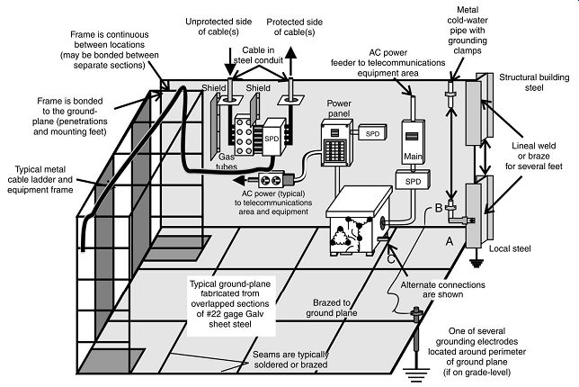
FIG. 29. Fully integrated SPD protection and grounding for the telecommunication
system.
Circuit protective elements and transient phenomena:
Fuses have been, until recently, the prime protective element in medium- and low voltage circuits, with current ratings from as low as 60 mA-1000 A or more. These protective elements can carry up to 5000 times their rated current for period of <5 ms.
These devices are manufactured with a wide range of characteristics that vary the speed of response (failure mode) with varying magnitudes of fault or overload currents vs time. Long-term failures can occur, caused by a continuous 20% overload, which won’t become evident for hours or days. The separation of the wire element during the rupture period (clearing of the overload) can cause surges due to the arcing across the separating pieces of the element. Many fuses have the wire element surrounded in silica as a current suppressant, for 'current limiting' action, and the rapid melting of the silica as it surrounds the ruptured element leads to enormous transient voltages across the opening element. (The impedance of the wire rupture becomes nearly 'infinite' instantaneously!) These phenomena cause stress in the associated fuses in adjoining phases of a three-phase system, and may lead to 'single phasing' in the system for indeterminate periods. The protected AC circuits tend to 'sag' just before the rupture by an amount depending on the fault current and source impedance, and the 'surge' after the complete rupture, particularly if the rupture time period is very short. The circuit will experience interference in the form of transient noise between the time of the current overload and the final clearing by the fuse element. The nominal ratings tend to show wide tolerances, as much as +/-20% is not uncommon, and thus this form of protection may not be accurate.
The general trend is to replace the fuse with a magnetic circuit breaker (MCB), capable of protecting all phases even when one phase only is effected. These devices exhibit only a resistive element in the circuit being protected, and offer additional protection in the form of ground leakage detection.
Earth (ground) leakage devices (single and three phase):
These devices operate by comparing the supply currents to the load return currents in a circuit. A difference in current, in excess of the mA rating of the device, results in the device operating to open all circuits, both phase(s) and neutral. A three-phase device can be obtained for three phase, three-wire operation or for three phase with neutral. When there is a leakage to ground, whether from any phase or neutral, the device will operate to protect the circuit, thus no connection between neutral and ground can exist downline of the unit. These units present a small series inductance on each line (phase and neutral) of the circuit.
Codes and guidelines:
We find examples of various codes, standards and guidelines that are available for the understanding of standards of transient voltage surge suppression. What has been referred to by manufacturers in the United States as TVSS, now is more easily referred to throughout the international community as a SPD.
==== 1. Codes, recommended practices, standards and guidelines for transient voltage surge suppression (TVSS)/(SPD)
| Top of Page | PREV: Effect of electric shock on human beings | NEXT: Power system analysis software | Index |