AMAZON multi-meters discounts AMAZON oscilloscope discounts
Power system automation can be defined as a system for managing, controlling and protecting an electrical power system. This is accomplished by obtaining real-time information from the system, having powerful local and remote control applications and advanced electrical protection. The core ingredients of a power system automation system are local intelligence, data communications and supervisory control and monitoring.
AMAZON multi-meters discounts AMAZON oscilloscope discountsNote: Power system automation is also referred to as substation automation.
What is power system automation?
Power system automation may be best described here:

FIG. 1. Functional structure of power system automation.
Power system automation, by definition, consists of the following main components:
- • Electrical protection
- • Control
- • Measurement
- • Monitoring
- • Data communications
Electrical protection:
Electrical protection is still one of the most important components of any electrical switchgear panel, in order to protect the equipment and personnel, and to limit damage in case of an electrical fault. Electrical protection is a local function, and should be able to function independently of the power system automation system if necessary, although it’s an integral part of power system automation under normal conditions. The functions of electrical protection should never be compromised or restricted in any power system automation system.
Control:
Control includes local and remote control. Local control consists of actions the control device can logically take by itself, For example bay interlocking, switching sequences and synchronizing check. Human intervention is limited and the risk of human error is greatly reduced.
Local control should also continue to function even without the support of the rest of the power system automation system. Remote control functions to control substations remotely from the SCADA master(s). Commands can be given directly to the remote-controlled devices. For example open or close a circuit breaker. Relay settings can be changed via the system, and requests for certain information can be initiated form the SCADA station(s). This eliminates the need for personnel to go to the substation to perform switching operations, and switching actions can be performed much faster, which is a tremendous advantage in emergency situations. A safer working environment is created for personnel, and huge production losses may be prevented. In addition, the operator or engineer at the SCADA terminal has a holistic overview of what is happening in the power network throughout the plant or factory, improving the quality of decision-making.
Measurement:
A wealth of real-time information about a substation or switchgear panel is collected, which is typically displayed in a central control room and/or stored in a central database. Measurement consists of:
- • Electrical measurements (including metering) - voltages, currents, power, power factor, harmonics, etc.
- • Other analog measurements, e.g. transformer and motor temperatures
- • Disturbance recordings for fault analyses.
This makes it unnecessary for personnel to go to a substation to collect information, again creating a safer work environment and cutting down on personnel workloads. The huge amount of real-time information collected can assist tremendously in doing network studies like load flow analyses, planning ahead and preventing major disturbances in the power network, causing huge production losses.
Note: The term 'measurement' is normally used in the electrical environment to refer to voltage, current and frequency, while 'metering' is used to refer to power, reactive power, and energy (kWh). The different terms originated due to the fact that very different instruments were historically used for measurement and metering. Nowadays the two functions are integrated in modern devices, with no real distinction between them; hence the terms 'measurement' and 'metering' are used interchangeably in the text.
Accurate metering for billing purposes is still performed by dedicated instruments.
Monitoring:
• Sequence-of-event recordings
• Status and condition monitoring, including maintenance information, relay settings, etc.
This information can assist in fault analyses, determining what happened when, where and in what sequence. This can be used effectively to improve the efficiency of the power system and the protection. Preventative maintenance procedures can be utilized by the condition monitoring information obtained.
Data communication:
Data communication forms the core of any power system automation system, and is virtually the glue that holds the system together. Without communications, the functions of the electrical protection and local control will continue, and the local device may store some data, but there can be no complete power system automation system functioning.
The form of communications will depend on the architecture used, and the architecture may, in turn, depend on the form of communication chosen.
Power system automation architecture
Different architectures exist today to implement the components of power system automation in practice. It’s important to realize that not one single layout can exclusively illustrate a power system automation system. However, the most advanced systems today are developing more and more toward a common basic architecture.
The modern system consists of three main divisions.
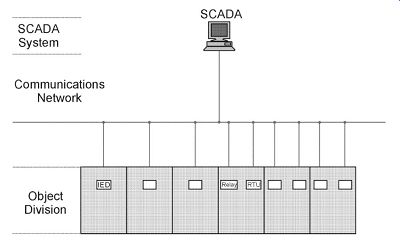
FIG. 2. Basic architecture of power system automation.
Object division:
The object division of the power system automation system consists of intelligent electronic devices (IEDs), modern, third generation microprocessor-based relays and/or remote terminal units (RTUs). The PLCs continue to play an important role in some systems. They receive analog inputs from the current transformers (CTs), voltage transformers (VTs) and transducers in the various switchgear panels, as well as digital inputs from auxiliary contacts, other field devices or IEDs, or the SCADA master. They are able to perform complex logical and mathematical calculations and provide an output either to the SCADA master, other field instruments or IEDs, or back to the switchgear to perform some command, for example open a circuit breaker.
The object division consists of the process level (field information from CTs, VTs, etc.) and the bay level (local intelligence in the form of IEDs, RTUs, etc.).
The communications network:
The communications network (comms network for short) is virtually the nervous system of power system automation. The comms network ensures that raw data, processed information and commands are relayed quickly, effectively and error-free among the various field instruments, IEDs and the SCADA system. The physical medium will predominantly be fiber-optic cables in modern networks, although some copper wiring will still exist between the various devices inside a substation.
The comms network need to be an 'intelligent' subsystem in its own right to perform the functions required of it, and is not merely a network of fiber-optic and copper wiring.
The communication network serves as the interface between the bay level and the SCADA station level, which might be a SCADA master station in the substation itself, or remotely in a central control room.
SCADA master:
The SCADA master station(s) forms the virtual brain of the power system automation system. The SCADA master receives data and information from the field, decides what to do with it, stores it (directly or after some form of processing), and issues requests and/or commands to the remote devices. Therefore, the SCADA master is effectively in control of the complete power system automation system.
Nowadays, a SCADA master consists simply of an advanced, reliable PC or workstation (with its peripheral and support hardware) and a SCADA software package. (In contrast with a few years ago when SCADA systems used to run on big mainframe computers or some form of complex proprietary hardware.) A SCADA master station may be installed in each substation of a power transmission network (station level), with all the substation SCADA stations forming part of a LAN or WAN (network level); or one SCADA master station may be directly in control of several substations, eliminating the station level.
| Top of Page | PREV: Finite element analysis; Grounding; Other programs; Further development of programs; Program suites; Conclusions | NEXT: (none) | Index |