AMAZON multi-meters discounts AMAZON oscilloscope discounts
Current transformers
All current transformers used in protection are basically similar in construction to standard transformers in that they consist of magnetically coupled primary and secondary windings, wound on a common iron core, the primary winding being connected in series with the network unlike voltage transformers. They must therefore withstand the networks short-circuit current.
There are two types of current transformers:
1. Wound primary type
2. Bar primary type.
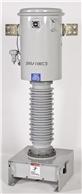
Wound type CT is shown.
The wound primary is used for the smaller currents, but it can only be applied on low fault level installations due to thermal limitations as well as structural requirements due to high magnetic forces. For currents greater than 100 A, the bar primary type is used. If the secondary winding is evenly distributed around the complete iron core, its leakage reactance is eliminated.
AMAZON multi-meters discounts AMAZON oscilloscope discountsPrimary, Secondary
++++ Wound primary; Primary--Secondary
++++ Bar primary
++++ Secondary winding is evenly distributed around iron core.
Protection CTs are most frequently of the bar primary, toroidal core with evenly distributed secondary winding type construction. The standard symbol used to depict current transformers.
++++ Standard symbol for current transformers
The basis of all transformers is that:
Amp-turns on the Primary = Amp-turns on the secondary e.g. 100 A × 1 turn = 1 A × 100 turns The primary current contains two components:
• An exciting current, which magnetizes the core and supplies the eddy current and hysteresis losses, etc.
• A remaining primary current component, which is available for transformation to secondary current in the inverse ratio of turns.
The exciting current is not being transformed and is therefore the cause of transformer errors. The amount of exciting current drawn by a CT depends upon the core material and the amount of flux that must be developed in the core to satisfy the output requirements of the CT. that is, to develop sufficient driving voltage required, pushing the secondary current through its connected load or burden. This can be explained vectorally.
++++ Vector diagram for a current transformer
Magnetization curve
This curve is the best method of determining a CTs performance. It’s a graph of the amount of magnetizing current required to generate an open-circuit voltage at the terminals of the unit. Due to the non-linearity of the core iron, it follows the B-H loop characteristic and comprises three regions, namely the initial region, unsaturated region and saturated region. Saturated region Unsaturated region Initial region V (V) Vk =Knee point
++++ Typical CT magnetization curve
Knee-point voltage
The transition from the unsaturated to the saturated region of the open-circuit excitation characteristic is a rather gradual process in most core materials. This transition characteristic makes a CT not to produce equivalent primary current beyond certain point. This transition is defined by 'knee-point' voltage in a CT, which decides its accurate working range.
AMAZON multi-meters discounts AMAZON oscilloscope discountsIt’s generally defined as the voltage at which a further 10% increase in volts at the secondary side of the CT requires more than 50% increase in excitation current. For most applications, it means that current transformers can be considered as approximately linear up to this point.
Metering CTs
Instruments and meters are required to work accurately up to full-load current, but above this, it’s advantageous to saturate and protect the instruments under fault conditions. Hence, it’s common to have metering CTs with a very sharp knee-point voltage. A special nickel-alloy metal having a very low magnetizing current is used in order to achieve the accuracy.
Following curve shows the magnetization curve of metering CT.
Protection CTs
Protective relays are not normally expected to give tripping instructions under normal conditions. On the other hand these are concerned with a wide range of currents from acceptable fault settings to maximum fault currents many times normal rating. Larger errors may be permitted and it’s important that saturation is avoided wherever possible to ensure positive operation of the relays mainly when the currents are many times the normal current.
++++ Metering CT magnetization curve
++++ Protection CT magnetization curve
Test set-up for the CT magnetic curve
It’s necessary to test the characteristics of a CT before it’s put into operation, since the results produced by the relays and meters depend on how well the CT behaves under normal and fault conditions.
++++ a simple test connection diagram that is adopted to find the magnetic curve of a CT.
++++ Circuit to test magnetization curve -- Current transformer
++++ Polarity markings of a CT
++++ Testing of a CT polarity -- Battery 9V
Polarity
Polarity in a CT is similar to the identification of +ve and -ve terminals of a battery.
Polarity is very important when connecting relays, as this will determine correct operation or not depending on the types of relays. The terminals of CT are marked by P1 and P2 on the primary, and S1 and S2 on the secondary. -- states that at the instant when current is flowing from P1 to P2 in primary, then current, in secondary must flow from S1 to S2 through the external circuit.
++++ shows the simple testing arrangement for cross-checking the CT polarity markings at the time of commissioning electrical systems.
Connect battery -ve terminal to the current transformer P2 primary terminal. This arrangement will cause current to flow from P1 to P2 when +ve terminal is connected to P1 until the primary is saturated. If the polarities are correct, a momentary current will flow from S1 to S2.
Connect center zero galvanometer across secondary of the current transformer. Touch or flick the +ve battery connection to the current transformer P1 primary terminal. If the polarity of the current transformer is correct, the galvanometer should flick in the +ve direction.
Open circuits of CTs
Current transformers generally work at a low flux density. Core is then made of very good metal to give small magnetizing current. On open-circuit, secondary impedance now becomes infinite and the core saturates. This induces a very high voltage in the primary up to approximately system volts and the corresponding volts in the secondary will depend on the number of turns, multiplying up by the ratio (i.e. volts/turn × no. of turns). Since CT normally has much more turns in secondary compared to the primary, the voltage generated on the open-circuited CT will be much more than the system volts, leading to flashovers.
SAFETY PRECAUTION--NEVER OPEN-CIRCUIT A CURRENT TRANSFORMER ON LOAD!!!
Secondary resistance
The secondary resistance of a CT is an important factor, as the CT has to develop enough voltage to push the secondary current through its own internal resistance as well as the connected external burden. This should always be kept as low as possible.
CT specification
A current transformer is normally specified in terms of:
• A rated burden at rated current
• An accuracy class
• An upper limit beyond which accuracy is not guaranteed (known as the accuracy limit factor, ALF), which is more vital in case of protection CTs.
In the relevant std. the various accuracy classes are in accordance with the following tables:
+--+ Limits of error for accuracy classes 0.1-1 (metering CT) -- ± Percentage Current (Ratio) Error at Percentage of Rated Current Shown Below; ± Phase Displacement at Percentage of Rated Current Shown Below
+--+ Limits of error for accuracy class 5P and class 10P (protection CT) -- Current Error at Rated Primary Current % Phase Displacement at Rated Primary Current Composite; Error at Rated Accuracy Limited Primary Current % Accuracy; Class Minutes; Centiradians; In terms of the specification a current transformer would, for example, be briefly referred to as 15 VA 5P20 if it were a protection CT or 15 VA Class 0.5 if it’s a metering CT. The meanings of these figures are as below:
Protection Metering Rated burden 15 VA 15 VA Accuracy class 5P 0.5 Accuracy limit factor 20 Class 1,0 (ALF is 20 times normal or rated current)
Class X current transformers
These are normally specified for special purpose applications such as busbar protection, where it’s important that CTs have matching characteristics.
For this type of CT an exact point on the magnetization curve is specified, e.g.:
1. Rated primary current
2. Turns ratio
3. Rated knee-point emf at maximum secondary turns
4. Maximum exciting current at rated knee-point emf
5. Maximum resistance of secondary winding.
In addition, the error in the turns ratio shall not exceed ±0.25%.
Connection of current transformers
Current transformers for protection are normally provided in groups of three, one for each phase. They are most frequently connected in 'star'. The secondary currents obtainable with this connection are the three individual phase currents and the residual or neutral current. The residual current is the vector sum of the three phase currents, which under healthy conditions would be zero. Under ground fault conditions, this would be the secondary equivalent of the ground fault current in the primary circuit.
++++ Star connection of current transformers
Sometimes, current transformers are connected in 'delta'. The reasons for adopting this connection are one or more of the following:
• To obtain the currents Ir-Iw, Iw-Ib, Ib-Ir
• To eliminate the residual current from the relays
• To introduce a phase-shift of 30° under balanced conditions, between primary and relay currents.
++++ Delta connection of current transformers
++++ Current distribution under ground fault conditions (I0 circulating inside the delta)
Terminal designations for current transformers
According to IEC publication 185, the terminals are to be designated. All terminals that are marked P1, S1 and C1 should have the same polarity.
++++ Marking of current transformers: (a) one secondary winding; (b) two secondary windings; (c) one secondary winding which has an extra tapping; (d) two primary windings and one secondary winding
Secondary grounding of current transformers
To prevent the secondary circuits from attaining dangerously high potential to ground, these circuits are to be grounded. Connect either the S1 terminal or the S2 terminal to ground. For protective relays, ground the terminal that is nearest to the protected objects. For meters and instruments, ground the terminal that is nearest to the consumer. When metering instruments and protective relays are on the same winding, the protective relay determines the point to be grounded. If there are taps on the secondary winding, which are not used, then they must be left open. If two or more current transformers are galvanic connected together they shall be grounded at one point only (e.g. differential protection). If the cores are not used in a current transformer, they must be short-circuited between the highest ratio taps and should be grounded. It’s dangerous to open the secondary circuit when the CT is in operation. High voltage will be induced.
Current transformer connections -- the various ways of connecting current transformers at various parts of an electrical system.
++++ Current transformers for a power transformer
++++ Current transformers monitoring cable currents
++++ CT connections in busbars
Test windings
It’s often necessary to carry out on-site testing of current transformers and the associated equipment but it’s not always possible to do primary injection because of access of test sets not being large enough to deliver the high value of current required.
Additional test windings can be provided to make such tests easier. These windings are normally rated at 10A and when injected with this value of current produce the same output as the rated primary current passed through the primary winding.
It should be noted that when energizing the test winding, the normal primary winding should be open circuited, otherwise the CT will summate the effects of the primary and test currents. Conversely, in normal operation the test winding should be left open circuited. Test windings do, however, occupy an appreciable amount of additional space and therefore increase the cost. Alternatively, for given dimensions they will restrict the size and hence the performance of the main current transformer.
Application of current transformers
In earlier sections, we have come across AC trip coils, which are to be designed to carry the normal and fault currents. However, it’s difficult to use the same for higher current circuits. In order to overcome the limitations as experienced by series trip coils, current transformers are used so that the high primary currents are transformed down to manageable levels that can be handled comfortably by protection equipment.
A typical example would be fused AC trip coils. These use current transformers, which must be employed above certain limits i.e., when current rating and breaking capacity becomes excessively high. Some basic schemes are:
Overcurrent
In this application, the fuses bypass the AC trip coils. Under normal conditions, the fuses carry the maximum secondary current of the CT due to the low-impedance path. Under fault conditions, I_sec having reached the value at which the fuse blows and operates, trip coil TC to trip the circuit breaker. Characteristic of the fuse is inverse to the current, so a limited degree of grading is achieved.
Overcurrent and ground fault
There are two methods of connection --one are the most economical arrangement for this protection.
++++ CTs for overcurrent use in series trip coils
++++ CTs for overcurrent and ground fault protection using series trip coils -- EF Instantaneous
++++ Economical use of overcurrent and ground fault configuration
Introducing relays
The electromechanical relays basically comprise of armature coils with mechanical contacts to energize a tripping coil of a breaker. The CTs are connected in the same way as seen in the earlier pictures. ++++ gives an overview of the various connections commonly adopted.
++++ Inverse overcurrent tripping characteristic -- Instantaneous relay
++++ Inverse overcurrent + instantaneous ground fault --Instantaneous E/F relay Instantaneous O/C relay
++++ More economic method --Instantaneous O/C + E/F relay
Inverse definite minimum time lag (IDMTL) relay
Here the relays are designed to have inverse characteristics similar to that of fuses and hence the fuses are eliminated in the CT connections.
++++ Overcurrent
++++ Overcurrent + ground fault
++++ IDMTL overcurrent + time lag ground fault
++++ IDMTL OC + EF relay with AC trip coils
| Top of Page | PREV: Instrument transformers--part 1 | NEXT: Circuit breakers | Index |