This guide covers a wide range of solid-state rectifiers and power supply circuits as used in industrial equipment, hobby circuits, and transmitter-receiver units of all types. Each circuit is complete with parts values and all the information necessary to build the power supply.
CIRCUIT WIRING
Although power transistors and rectifiers are very rugged devices that can undergo considerable rough treatment, unnecessary mechanical shock is to be avoided. It is important to avoid extreme shock or excessive bending or twisting of the device leads when they are being soldered. When operated within their normal ratings, these components will provide a long and useful life. It is possible, however, that even small excessive voltage' or excessive power demands may instantaneously destroy a unit such as a power transistor.
When you are building or experimenting with new circuits, it is important to take certain precautions. The polarity of the power supply voltage for the circuit should be checked and then double checked. An incorrect polarity can damage the transistors as well as any electrolytic capacitors used in the circuit. After a new circuit is built and it is being tested, the voltage should be applied in easy stages, beginning with a value below normal, to check the basic wiring to see if the circuit operation is correct. It is important to be very careful of high-voltage surges at all times. If an unregulated 12-volt electronic power supply is constructed, it is possible to load this power supply with a storage battery in order to stabilize the voltage.
If the power-supply circuit appears to be operating properly, the rectifier current and collector current in the power-transistor stages of a regulator, where one is used, should be measured and the bias adjusted if necessary. This will prevent any long-term damage by operating a transistor beyond its normal ratings.
All of these circuits have been tested; they have been conservatively designed and will provide excellent performance. No layouts and mechanical details are given since they vary widely with different requirements as well as with the sizes and shapes of the components employed. The choice of component parts is very important since the performance of these circuits depends on the quality of the components and the care taken in layout as well as the care taken in construction. In almost all cases, transformers can be obtained from local parts dealers by specifying the required characteristics. The wattage ratings given for resistors are based on methods of construction that provide adequate ventilation, and compact installations with ventilation less than normal may require resistors of higher-wattage ratings.
Capacitor voltage ratings are the minimum d-c working voltages required. Paper, mica, or ceramic capacitors with higher voltage ratings than those given may be used if the physical sizes of such capacitors will not affect the equipment layout. Where electrolytic capacitors with much higher voltage ratings than those given are used, they may not "form" completely at the circuit operating voltage, and as a result, the effective capacitances may be below their rated values.
For reference, some major manufacturers of power transformers follow:
Columbus Process Company Columbus, Indiana Microtran Company, Inc.
145 East Mineola Avenue Valley Stream, New York Mid-West Coil and Transformer Co.
1642 North Halstead Chicago, Illinois Stancor Electronics, Inc.
3501 West Addison Street Chicago, Illinoi
Triad Transformer Corporation 4055 Redwood Avenue Venice, California
Thompson-Ramo-Wooldridge, Inc. Electronic Components Division 666 Garland Place Des Plaines, Illinois
Thordarson 7th and Bellmont Mt. Carmel, Illinois United Transformer Corporation 150 Varick Street, New York, New York
HEAT SINKS
Temperature extremes can be damaging to a transistor. Power transistors should usually be mounted on a heat sink or radiator, and where the collector is above ground potential, the sink should be insulated from the chassis. It is possible to bolt the transistor to the chassis with insulated bolts and to use a washer between the transistor and chassis.
Excessive heat is an enemy of power transistors. Since heat increases the collector cutoff current, which reduces the power output, further heat is then developed; it is possible that this might result in thermal runaway. A circuit can be stabilized by using a thermistor or temperature-sensitive resistor in the base circuit so that an increase in temperature decreases the base-to-emitter voltage, thus stabilizing the collector cutoff current.
Courtesy Delco Radio Div., General Motors Corp.
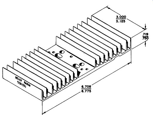
Fig. 1. Delco 7281351 heat sink. Courtesy Delco Radio Div., General Motors Corp.
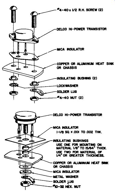
Fig. 2. Mounting transistors on heat sink.
Transistor heat sinks are necessary in most power-transistor applications. Fig. 1 shows the Delco 7281351 heat sink made of extruded aluminum. This has a nominal weight of 8 ounces and a surface area of about 100 square inches. The mounting of two different types of transistors in this heat sink is shown in Fig. 2. The use of these mounting kits will allow the insulated mounting of transistors to this heat sink. The effectiveness of a particular heat sink depends on the contact interface between the transistor and the heat-sink surface. It is necessary that the most intimate contact be made for heat transfer, and the effectiveness of this contact depends on the meeting of the surfaces and the pressure holding them together. The use of a grease or oil is a beneficial technique to minimize the effect of any surface irregularity where the two surfaces meet. A suggested type is silicone oil type 200 (Dow Coming Corp., Midland, Michigan). A different type of heat sink (Delco type 7281357) is shown in Fig. 3. This type of heat sink has an insulated spacer that is used to allow insulation of the entire heat sink from the chassis so that the transistor can be mounted directly to the heat sink.
Courtesy Delco Radio Div., General Motors Corp.
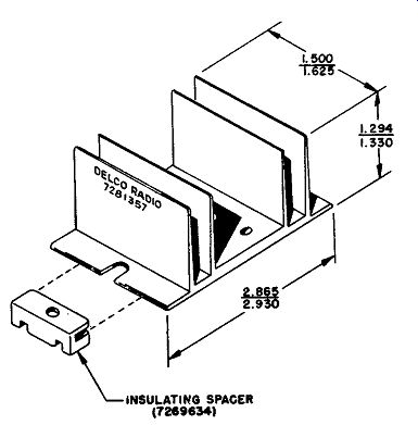
Fig. 3. Delco 7281357 heat sink.
SILICON RECTIFIERS
Silicon rectifiers can be considered as power diodes using semiconductor materials. They have a low forward resistance and a high back resistance; these rectifiers can be operated at temperatures up to 200°C, and with currents of 100 amperes or more at voltage levels up to 1000 volts.
There are many sizes and shapes of silicon rectifiers, including the smallest types usually used for power supplies (Fig. 4); these glass diodes have pigtail leads. Plug-in types (Fig. 5) have higher ratings than the glass diodes. The largest solid-state rectifiers are shown in Fig. 6. For rectifier stacks, units such as those shown in Fig. 7 are used.
Silicon rectifiers provide a high-rectification efficiency because of their high forward-to-reverse current ratios; when they are properly used, they are excellent rectifiers in power-supply circuits. Although they can operate at high temperatures, silicon rectifiers are sensitive to sudden temperature change; thus, any sudden rise in junction temperature can cause a rectifier failure.
During reverse bias a small amount of current flows, but at a specific reverse voltage, depending on the type of diode, there is a very sharp increase in reverse current. This voltage is known as the avalanche, breakdown, or zeller voltage. This effect is used in zener diodes for regulation.
A silicon rectifier normally requires a forward voltage of between 0.4 and 0.7 volt, depending on the rectifier type. Since the rectifier has a small mass, the forward voltage drop must be carefully con trolled to prevent exceeding the maximum value for the particular device.
Courtesy-International Rectifier Corp.
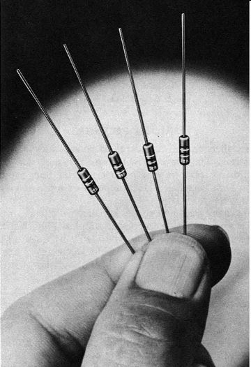
Fig. 4. Glass-diode silicon rectifiers.
Silicon rectifiers were originally developed for use in dc-to-dc converters, battery chargers, mobile power supplies, and other applications. Because of their excellent characteristics, they are now being used in power supplies for all types of electronic equipment.
In addition to the usual diode rectifier, the silicon controlled rectifier (SCR) is a powerful circuit aid where variations in power are required. Control of the gate input makes provisions for different firing points on the a-c cycle. SCR's are generally used in power control circuits, while standard power-supply design most often uses diodes.
Courtesy International Rectifier Corp.
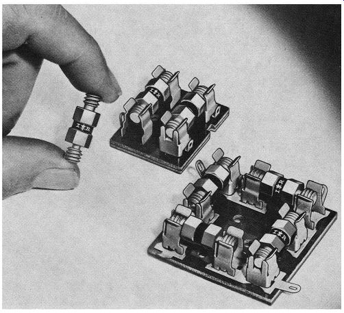
Fig. 5. Plug-in silicon rectifiers.
Courtesy International Rectifier Corp.
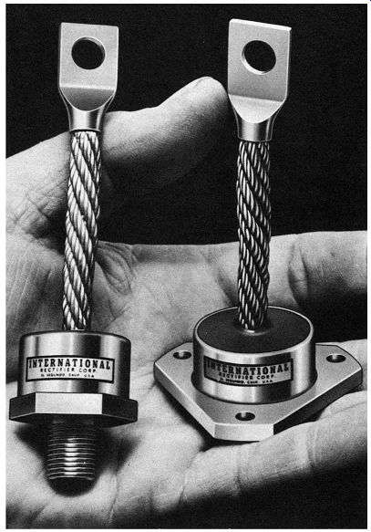
Fig. 6. High-ampere solid-state rectifiers.
Courtesy International Rectifier Corp.
Fig. 7. High-power silicon-rectifier stacks.
RECTIFIER CHARACTERISTICS
In choosing a rectifier circuit the parameters under consideration are the d-c voltage required, the current required, and the amount of ripple in the output circuit. Ratings for silicon rectifiers are important in considering their specific applications in a particular circuit. The maximum peak-reverse voltage (inverse voltage) is the highest amount of reverse voltage that can be applied to a particular rectifier before avalanche breakdown is reached. These ratings range from about 50 volts up to as high as 1000 volts for diodes with a single junction.
It is possible, of course, to have any number of rectifiers in series to provide the necessary overall peak-reverse voltage required by a particular circuit.
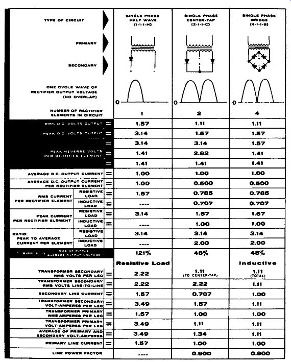
Chart 1. Characteristics of common rectifier circuits.
Current is usually specified in three different ways. The maximum average forward current is that rectifier current which is allowed to flow in the forward direction at a specific ambient or case tempera ture. Average currents are typically from 0.5 ampere to as much as 250 amperes for special rectifier types. The maximum recurrent forward current is the maximum repetitive instantaneous current in a forward direction under specific conditions. The maximum surge current is the greatest nonrepetitive peak current that can occur in a single forward cycle. Surge currents or peak currents such as this usually occur when the equipment is turned on or when there are unusual transients in the line.
To prevent excessive heat rise, silicon rectifiers can be mounted on heat sinks attached to the heat-conducting side of the rectifier. A heat sink will allow the rectifier to dissipate a large amount of heat, thus protecting the rectifier circuit against damage. The size of a heat sink for a specific application depends on the maximum average forward current and the allowable rectifier temperature.
It is possible to use silicon rectifiers in series when the expected applied reverse voltage is greater than the maximum peak-reverse voltage rating for a particular rectifier cell. When cells are used in series, it is very important that the applied voltage be divided equally across the individual rectifiers; otherwise an instantaneous voltage greater than the rated maximum might be applied across an individual cell. For this purpose shunt resistors and shunt capacitors are used to equalize the voltage applied to the series resistors; both resistors and capacitors should be used in a circuit if it is going to be carrying both DC and ac.
Rectifiers can be used in parallel when the maximum average forward current required for a particular application is greater than the maximum average forward current rating for an individual rectifier cell. A resistor or inductor should be added in series with each cell in order to avoid differences in voltage from appearing across the parallel rectifiers.
Characteristics of seven basic rectifier circuits are shown in Chart 1.
Assuming a zero forward-voltage drop and zero reverse current in the rectifiers, the table compares these seven circuits for various parameters. There is a small error in using this table, but this is usually not significant because the voltage drop in the forward direction is assumed to be zero, as is the reverse current.
The single-phase half-wave circuit (A) delivers one current pulse for each cycle of a-c voltage input. The single rectifier cell has the entire current flow, and there is a great deal of output ripple. A circuit of this type is used principally in low-voltage high-current applications, as well as in low-current high-voltage applications.
The single-phase full-wave circuit (B) has a center-tapped high voltage winding, with a higher peak-to-average voltage ratio and less ripple than the single-phase half-wave circuit. Large audio amplifiers and television receivers quite commonly use this type of rectifier.
Four rectifiers are used in the single-phase full-wave bridge circuit ( C) which does not require the use of a transformer center tap.
This circuit provides twice as much output voltage as the single-phase full-wave circuit for the same transformer voltage. The single-phase full-wave bridge applies half as much peak-reverse voltage to each individual circuit cell, and allows only half of the total current to flow through each cell. Circuits of this type are quite often used in radio transmitters.
Three-phase circuits are usually found in industrial equipment and in transmitters of high power. The three-phase wye circuit (D) uses three rectifier cells and has considerably less ripple than any of the single-phase circuits. This circuit also allows one-third of the total current to flow through each individual rectifier cell; a circuit of this type is used in alternator rectifiers in automobiles.
The three-phase wye, full-wave bridge circuit (E) uses six rectifier cells. In this circuit two half-wave rectifiers are connected in series across each leg of a high-voltage transformer; this circuit delivers twice as much voltage output as the three-phase wye, half-wave circuit for the same voltage conditions. There is also an extremely low ripple percentage and a very low ratio of peak-to-average voltage.
The six-phase star circuit (F) uses six rectifiers and allows the least amount of total current to flow through each cell. Only one sixth of the total current will flow through each rectifier cell.
The three-phase double wys, an interphase-transformer circuit ( G), uses six individual half-wave rectifiers in parallel and delivers six current pulses per cycle. This circuit will deliver twice as much output current as the three-phase wye, half-wave circuit.
Filter circuits are used to smooth the ripple in the output of a rectifier circuit, and a smoothing filter uses an iron-core choke together with one or more capacitors. In choosing a filter for a particular circuit, the load impedance is an integral part of the filter design since the load affects the performance of the filter. The purpose of the choke is to provide a high impedance to the ripple voltage, while the capacitor stores energy between voltage peaks.
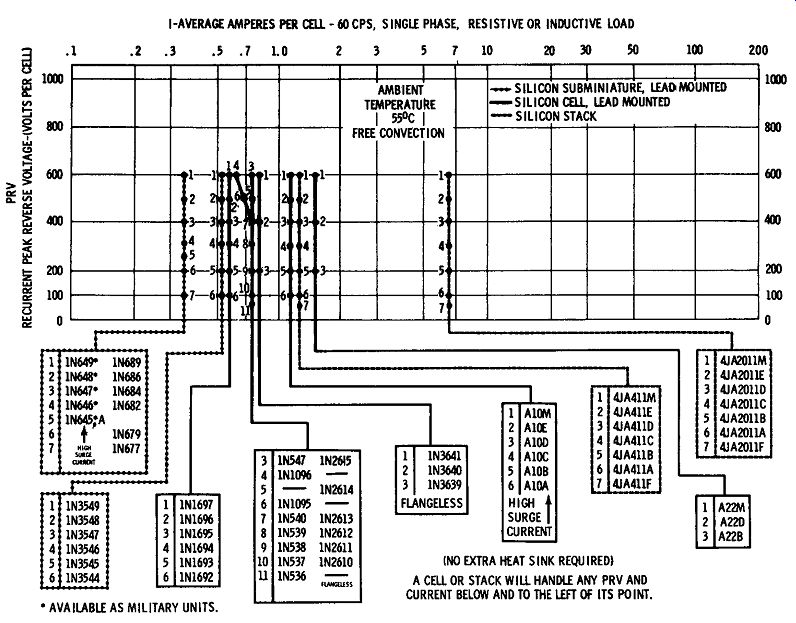
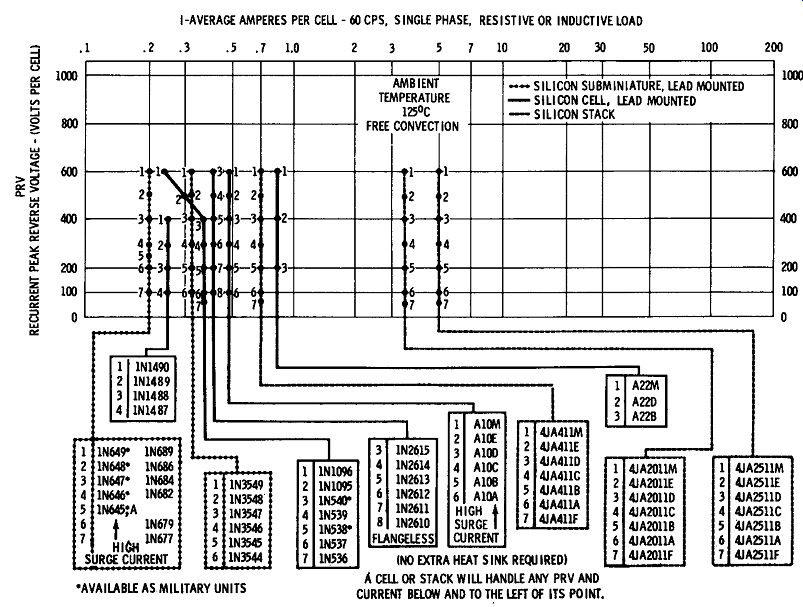
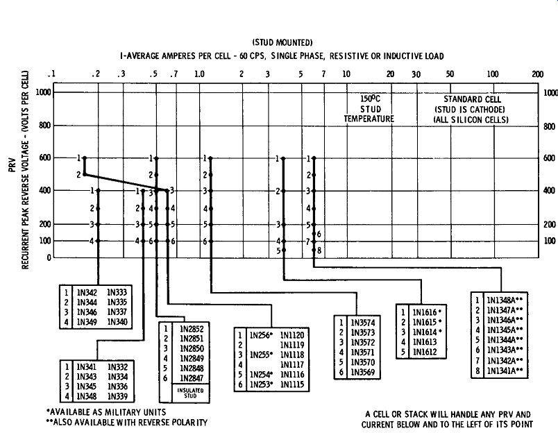
Charts 2, 3, and 4 are rectifier selection charts. Complete instructions on
how to use these charts precede them.
A HANDY SELECTION CHART TO SILICON AND GERMANIUM RECTIFIER COMPONENTS
1. Select applicable chart.
2. Locate average current I per rectifier cell on horizontal axis.
3. Move vertically to intersection of average current requirement with recurrent peak reverse voltage (PRV) requirement.*
4. Find the first numbered dot above and to the right of the intersection point located in Step 3. The corresponding rectifier cell type indexed in the box below the dot is the optimum rated cell for the application.
ADDITIONAL INFORMATION:
0
2. Ambient = 55°C Free Convection (Rectifier' cell furnished with own heatsink).
3. Ambient = 125°C Free Convection (Rectifier cell furnished with own heatsink).
4. Stud mounted rectifiers (cell must be attached to heat• sink provided by user).
Stud Temperature = 150°C.
E) Rectifier Circuit Single Phase Half Wave Single Phase Centertap Single, Phase Bridge Three Phase Halfwave Three Phase Bridge Average Current Per Cell I= DC Load Current
:I= 1 h x DC load Current I= 1/.1 x DC load Current l = 1/i x DC load Current I= 1/J x DC Load Current
E) Rectifier Circuit Recurrent Peale Reverse Voltage Single phase halfwave
-resistive load PRV = 1.41 x AC supply voltage
-capacitive load PRV = 2.82 x AC supply voltage
Single phase centertap PRY = 2.82 x AC secondary voltage (line to centertap)
Single Phase bridge PRY = 1.41 x AC supply voltage Three phase halfwave PRY = 2.45 x AC secondary voltage (line to neutral)
Three phase bridge PRY = 2.45 x AC supply voltage (line to line)
Additional PRY rating will be necessary if voltage transient above the normal line voltage occur.
Example: Requirements: 5 amps, 350 v PRV per rectifier cell, 55°C free convection ambient. Cell with heatsink required.
Solution: In Chart 2, point 3 is just above and to the right of intersection of 5 amperes and 350 v. In corresponding box below chart, point 3 is identified
01 General Electric type 4JA20l1D rectifier stack.
Chart 2
Chart 3
Chart 4