VOLTAGE REGULATOR WITH OVERLOAD PROTECTION
This circuit shows a voltage regulator with overload protection for the series transistor. A short circuit in the load will cause the series transistor to act as the load in most voltage-regulator circuits, and this can damage the transistor under these conditions. Because the series transistor is directly in the current path of the load, protection is required in a very short time. Three methods of protection are: (1) protection by load switching, (2) protection by current interruption, and (3) protection by current limiting.
This circuit shows current interruption, which is a dependable method of protection where the overload can be detected and interruption of the load circuit can be obtained before there is damage to the transistors acting as regulators. The circuit shows a complete regulator with a 115-volt input to a 2-to-1 stepdown power transformer; output of this regulator is 60 volts.
In this circuit the 2Nl601 controlled rectifier will conduct within one microsecond after a short circuit is placed across the regulator load. The 1-ampere fuse will open within three to four milliseconds. In the same type of circuit without the controlled-rectifier protection, the same 1-ampere fuse would need about 400 milliseconds in order to open, and by this time the transistor would probably be damaged. Thus, this circuit provides regulation with protection for the series transistor, which is the 2N389. The series resistance that this transistor presents to the circuit depends on the 2N656 which amplifies the error voltage obtained from the 2N343B. The 2N343B compares a portion of the output voltage with the voltage developed across the 1N754 zener diode.
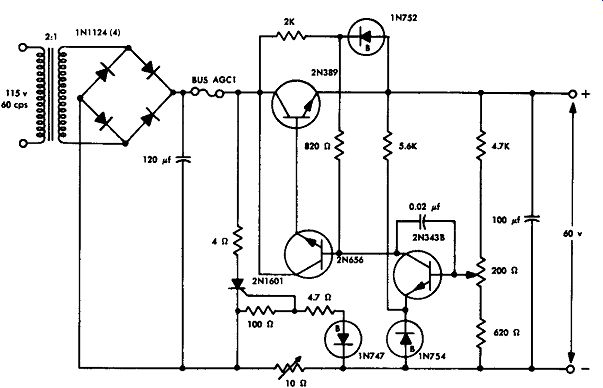
---Voltage regulator with overload protection.
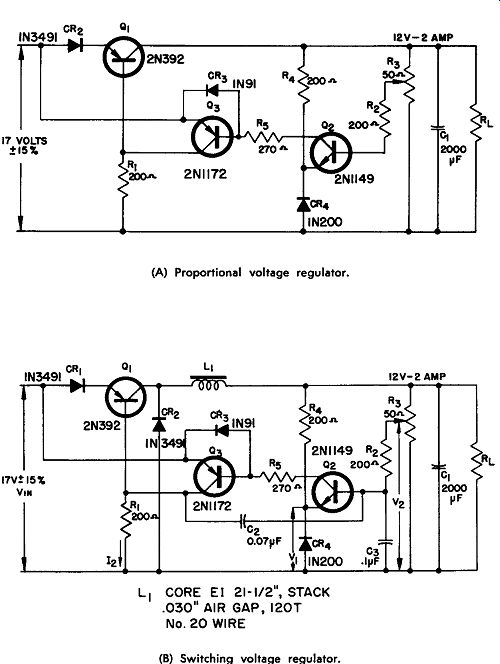
SWITCHING VOLTAGE REGULATOR
A proportional voltage regulator is shown in Fig. A. In this circuit a voltage proportional to the output is compared to a voltage of the reference diode (CR4) in the emitter circuit of transistor Q2. A voltage proportional to the output voltage is obtained across the tap on resistor R3. A differential signal is amplified by transistor Q3, and the output signal of this differential amplifier is used to control the current in series transistor Q1. Q1 is effectively a variable series resistance. Thus, for this circuit a 17-volt input will provide a regulated output of 12 volts at 2 amperes.
Fig. B effectively shows the same circuit except that an inductance (L1), a capacitance (C2), and a diode (CR2) are added to the circuit; these additions change the circuit into a switching type of regulator. If in Fig. B capacitor C2 is disconnected, there is no feedback, and the remaining circuit will be a proportional voltage regulator.
When, however, this capacitor is connected in the circuit, the operation is in the switching mode since there is a positive feedback loop and oscillations will start. The base current of transistor 0 2 has two individual components---one is the charge and discharge of capacitor C2, while the second component is proportional to the difference between voltages V 1 and V 2. Transistors Q2 and Q3, together with capacitor C2, form a free-running multivibrator. This multivibrator, in effect, turns on and off transistor Q1, which is the series transistor; in effect, this is the switching mode of operation for this regulator.
Filter reactance L1 is used to isolate transistor Q1 from filter capacitor C1 so that voltage-saturated operation is possible.
Resistor R1 determines the base current of transistor Q1, and the value for this resistor is determined by dividing the input voltage by the base current for maximum load. Resistor R2 is part of the time constant network that controls the frequency of oscillation, while resistor R3 is used for adjustment of the output voltage. Resistor R4 provides a bias current to the voltage-reference diode CR4, while resistor R5 limits the current through transistor Q2 if there is a short in transistor Q1.
Capacitor C1 is a filter capacitor, capacitor C2 is a feedback capacitor which determines the frequency of oscillation, while capacitor Ca controls the frequency of oscillation as well as having the function of suppressing any parasitic oscillations.
There are four diodes in this circuit; CR1 provides bias for transistor Q3 and allows Q3 to apply reverse bias to Q1 ; CR2 is a clamping diode while CR3 reduces the leakage in transistor Q3. CR4 is the voltage-reference diode and this diode has a positive temperature coefficient.
The regulation characteristics for this circuit are shown in Fig. C.
---------- Voltage regulators.
(A) Proportional voltage regulator.
(B) Switching voltage regulator.
(C) Regulation characteristics.
SERIES VOLTAGE REGULATOR
This circuit shows three transistors in a series voltage-regulator circuit; two of these transistors are type 2N1481, while one is a type 2N1489. In series voltage regulators of this type, a cascade d-c amplifier is used to amplify a difference signal, or an error, which is obtained by means of a comparison between part of the output voltage and a reference voltage. The amplified error signal is used as the input to the regulating element, which is in series with the load.
In this circuit a portion of the output voltage is applied to the base of transistor Q1, while the zener 12-volt diode is tied to the emitter of the same transistor.
Transistor Q2, then, acts as a differential, or error, amplifier whose input signal is the difference between the reference voltage and the voltage which is proportional to the output. Transistor Q2, in effect, controls series transistor Q3, which provides the necessary regulation.
This circuit, as shown, accepts a voltage input of 45 volts, ±5 volts, and produces a regulated 28-volt output.
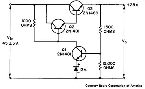
------------- Series voltage regulator.
SERIES VOLTAGE REGULATOR
This circuit shows a series type of voltage regulator with an adjust able output. Input to this circuit is 40 to 50 volts DC, while the output can be adjusted from 22 to 30 volts DC for a current from 0 to 10 amperes. Line regulation is within 1 % , and load regulation is within 0.5%. A 12-volt reference diode is used to provide a voltage which is compared to a portion of the output voltage; this difference, or error, voltage is amplified and used to control the three series transistors type 2N2016.
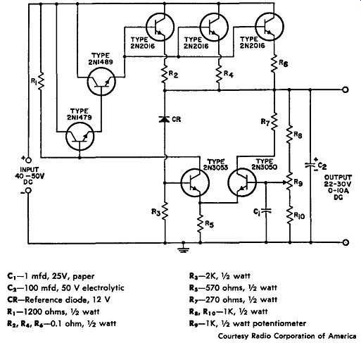
------------ Series voltage regulator.
C1-1 mfd, 25V, paper
C2- 100 mfd, 50 V electrolytic
CR-Reference diode, 12 V
R1-1200 ohms,½ watt
R2 , R4 , R6 -0.1 ohm, ½ watt
R3 -2K, ½ watt
R5-570 ohms, ½ watt
R7-270 ohms, ½ watt
R8, R10-1K, ½ watt
R9 -1K, ½ watt potentiometer
SHUNT VOLTAGE REGULATOR
This circuit shows a two-transistor shunt voltage regulator using one transistor, type 2N1485, and one type 2Nl481. Shunt regulators of this type are less complex than series regulators, although they are not quite as efficient. A shunt regulator uses a voltage-reference element and a shunt element. In this circuit the output voltage re mains constant because the shunt-element current changes when either the input voltage or the load current changes. The change in the shunt current appears as a change in voltage across the resistor that is in series with the load.
This circuit has an input of 49 volts ±7 volts, and an output of 28 volts as shown. The series resistance required in this case is 18 ohms.
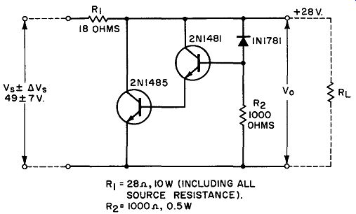
--------------- Shunt voltage regulator.
SERIES VOLTAGE REGULATOR
This circuit shows a simple three-transistor series voltage regulator with a voltage regulation of 3.5%. The input to this circuit is from 40 to 50 volts DC, while the output is 28 volts DC, with a current up to 1 ampere. A 12-volt reference diode is used to provide a voltage which is compared to a portion of the output voltage. The difference voltage is then amplified by the 2N1481 and applied to the base of the series transistor 2N1489.
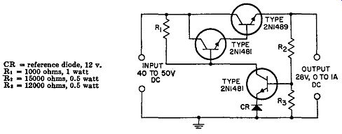
--------------- Series voltage regulator.
SERIES VOLTAGE REGULATOR
This circuit shows six transistors used in a series type of voltage regulator to produce regulation within 2.5 % . The input is from 75 to 160 volts DC, and the output is 70 volts for a current from 0 to 4 amperes. A 33-volt reference diode is used to provide a comparison to produce the difference voltage; this voltage is amplified and used to control the three transistors type 2N1489 through which the load current is drawn.
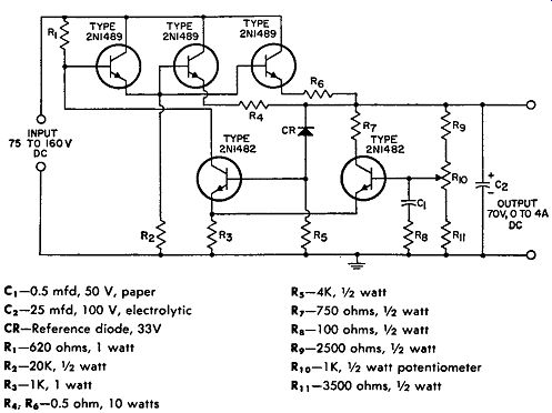
-------------- Series voltage regulator.
C1-0.5 mfd, 50 V, paper C,-25 mfd, 100 V, electrolytic CR-Reference diode, 33V R, -620 ohms, 1 watt R2-20K, 1 12 watt R3- 1K, 1 watt R4 , R6 -0.5 ohm, 10 watts R5-4K, ½ watt R7-750 ohms, 1 12 watt Ra-1 00 ohms, ½ watt R9-2500 ohms, ½ watt R 10 - 1 K, ½ watt potentiometer R11 -3500 ohms, ½ watt