Bad Cable Grounding
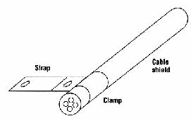
Above: A cable shield clamp is a much better choice than pigtail ground.
Poor cables and cable design very often lead to RF immunity issues.
Solution: Circumferential (360 degrees) are optimum; Shield “pigtails” are poor.
AMAZON multi-meters discounts AMAZON oscilloscope discounts
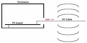
Divert current back to the shielded enclosure.
• Proper termination of the cable shield back to the enclosure is paramount.
Use high-impedance ferrite chokes to block current.
Connector penetrates through shield: another example of poor EM (electromagnetic) immunity
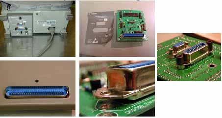
Above: Module tested for EMC is found to be: unshielded, main
connector ground shells has no connection with mate, connectors penetrate
enclosure. May be improved like here...
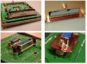
Above: Some improvement: Module halves copper-plated,
finger stock added to connectors and ribbed main connector ground shell
connects with mate.
An Ideal Cable-Grounding Strategy
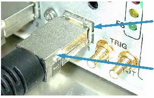
Above: A very suitable I/O connector: (top
arrow) Note the design
incorporates an integrated grounding connection, that solidly connects
shielded enclosure with connector ground shell in multiple locations.
(bottom arrow) Connector ground shell connected to cable shield.
Ideal cable grounding design – cable shield connected properly to metal enclosure.
Improved Cable/Connector Grounding Strategy
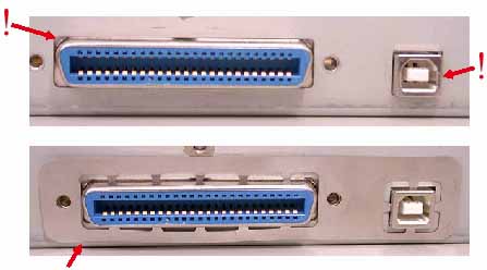
Above: Bottom image shows metal “shim” with “fingers” inserted
to shunt internal noise currents.
| EMC Top Ten: 1 | EMC Top Ten: 3 |