Crosstalk
Frequently occurs due to a self-compatibility problem that happen when noisy source currents are near sensitive analog, or low-level digital signals.
Solutions:
- Route power and signals in separate cables -- and keep those cables several inches from each other.
- Use shielded cables.
- In the case of circuit trace couplings, use additional separation or grounded “guard” traces between source and receptor traces.
AMAZON multi-meters discounts AMAZON oscilloscope discounts
Crosstalk found in Solid Ground Planes
Crosstalk between two conductors depends on their mutual inductance and capacitance. Often, inductive crosstalk is dominant.
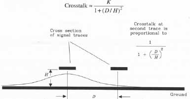
Above: Cross-section of two traces showing crosstalk. Crosstalk = K / (1
+ (D / H)2)
Minimizing Crosstalk via a Guard Trace
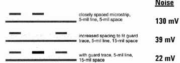
Above: Three different microstrip structures tested
for noise at the receiver of the victim line.
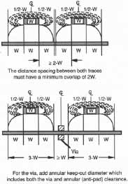
Use the “3W” Rule During Layout
- Clocks and periodic signals have a highly-probable chance of creating crosstalk in other traces.
- Reduce crosstalk effects via the “3W” rule: make sure all critical traces are “buffered” by at least 3 trace-widths surrounding each potential source and victim trace.
- Increase trace spacing from 1W to 3W; this will decrease far-end crosstalk by 65%.
Differential Pair Traces and the “3W” Rule
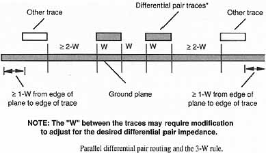
Most EMI/EMC engineers consider 3-5W the absolute minimum spacing for any critical trace to board edge spacing.
| EMC Top Ten: 6 | EMC Top Ten: 8 |