AMAZON multi-meters discounts AMAZON oscilloscope discounts
If the setting is an industrial environment, the grounding systems may:
- carry signal and power return currents
- form references for analog and digital circuits
- bleed off built-up charge (discharge)p
- safeguard people and equipment from faults, over current and lightning
- etc.
Any current flow in a grounding system can create a potential differences (voltage). Lightning strikes or other transient events can create hundreds or even thousands of volts. Hence, grounding must be incorporated into the system from the beginning so that the circuit or system can effectively operate in the intended environment and pass safety, emissions and interference requirements.
Proper grounding is depends on many factors:
- frequencies of signals running through cabling and devices
- impedances
- length of cabling required
- safety issues (i.e. electrical hazards)
When designing/engineering a ground or troubleshooting a grounding problem, the first thing one must determine is where the current is flowing. When several kinds of grounds coexist in a system or circuit, the current may not return by the assumed path.
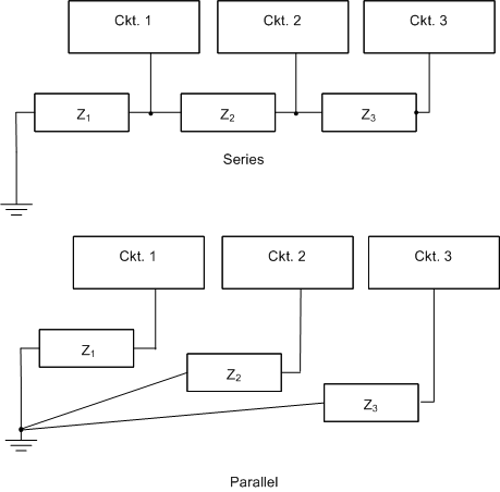
The best type of ground for low-frequency applications is the single-point ground (see the Figure below). The series connection, or daisy chain, should not be used when sensitive circuitry or cabling is involved because return currents from the three circuits flow through the common ground impedances linking the circuits. The "ground" potential of ckt. 1 is not only determined by its return current through impedance Z1 but also by the return currents from circuits 2 and 3 through the same impedance. This effect is called common-impedance coupling and is an important method of noise coupling.
The preferred ground is the parallel connection. It’s normally more difficult and more costly to implement due to the amount of wiring involved. First, determine the circuit’s common-impedance coupled noise immunity when choosing between these ground configurations. Most systems use a combination of both circuit designs.

Above: A single-point grounding scheme.
Related article: The
Basics of Electrical Grounding and Ground
Loops