AMAZON multi-meters discounts AMAZON oscilloscope discounts
Because this guide is about radio antennas it's necessary to also spend some time on the topic of antenna grounds. The effectiveness and safety of a radio antenna often hangs on whether or not it has a good radio frequency (RF) ground. Poor grounds cause most forms of antenna to operate at less than best efficiency (sometimes a whole lot less). In fact, when transmitting it's possible to burn up between 50 and 90% of your RF power heating the ground losses under the antenna, instead of propagating into the air.
Ground resistances can vary from very low values of 5 ohms, up to more than 100 ohms (5-30 ohms is a frequently quoted range). RF power is dissipated in the ground resistance, so is not available for radiation. The factors that affect the ground resistance include the conductivity of the ground, its chemical composition, and its water content.
The ideal ground depth is rarely right on the surface, and , depending on the local water table level, might be a couple of meters or so below the surface. It is common practice among some amateur radio operators to use the building electrical ground wiring for the RF antenna ground of their station. Neglecting to install an outdoor ground that will properly do the job, they opt instead for a single connection to the grounded 'third wire' in a nearby electrical outlet. Besides being dangerous to work with, unless you know what you are doing, it's also a very poor RF ground. It is too long for even the low RF bands, and radiates RF around the house in large quantity. Stations that use the household electrical wiring as the radio ground tend to cause television interference, and other electromagnetic interference both in their own building and in nearby buildings.
Other people use the plumbing piping in the house, but this is also a problem. While the cold water pipe entering older houses is metal, and is buried for quite a distance underground, it's also a single conductor, and is often made of a metal that's not optimal for radio work. Also, in modern buildings, the main water service and the distribution pipes in the plumbing system of the building may well not be metal at all, but rather PVC or some other insulating synthetic material. Even if you get a metal water pipe, if it's the hot water pipe then no effective ground exists. There is also a very severe danger of hooking your ground to the gas service line, which could cause a fire or explosion. In the USA, gas pipes are usually painted black, or are unpainted, but enough water pipes also fit this description that it's good practice to avoid the pipes in a building when searching for a radio grounding solution.
TRADITIONAL RADIO GROUNDING SOLUTIONS
The goal in making a radio ground is to provide a low resistance path to the earth for radio signals. An additional goal is to make a path to the earth for lightning that strikes the antenna, or even nearby (see Section 2 for the use of lightning arrestors in antenna lines).
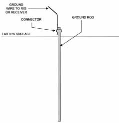
Ill. 1
We can reduce the ground resistance by either altering the composition of the earth surrounding the ground point, or by using a large surface area conductor as the ground point. Ill. 1 shows the traditional ground rod used by small radio stations, including amateur and receive-only stations. Use either a copper (or copper-clad steel) rod at least 2-3 m long.
Electrical supply houses, as well as amateur radio and communications equipment suppliers, also sell these ground rods. Do not use the non-clad steel types sold by some electrical supply houses. They are usable by electricians when making a service entrance ground in your home or workplace, but RF applications require the low skin resistance of the copper-clad variety. The rod need not be all copper, because of the skin effect forcing the RF current to flow only on the outer surface of the rod. Try to use a 2.5m or longer rod if at all possible, because it will work better than the shorter kind.
Do not bother with the small television antenna 100-150 cm ground rods; they are next to useless for high-frequency (HF) radio stations. Drive the ground rod into the earth until only a few centimeters remain above the surface. Connect a heavy gage ground wire from your station to the ground rod (some people use heavy braid or the sort once used for the return connection from the battery to the body of an automobile; an additional source is salvaged braid from the heavier gages of coaxial cable). The ground wire should be as short as possible. Furthermore, it should be a low-inductance conductor. Use either heavy braid (or the outer conductor stripped from RG-8 or RG-11 coaxial cable), or sheet copper. You can buy rolls of sheet copper from metal distributors in widths from 10 cm up to about 50 cm. Some amateurs prefer to use 17.5 cm-wide roofing foil that's rated at a weight of 1.5 kg/m. Sweat solder the ground wire to the rod. You can get away with using mechanical connections like the electricians use, but will eventually have to service the installation when corrosion takes its toll. I prefer to use soldered connections, and then cover the joint with either petroleum jelly or acrylic spray lacquer.
Another alternative is to use a copper plumbing pipe as the ground rod.
The pipe can be purchased in 2-5m lengths from plumbing supply shops or hardware stores. The pipe selected should be 19 mm in diameter or larger.
Some people report using up to 50mm diameter pipe for this application.
The surface area of the hollow pipe is greater than that of a solid rod of the same diameter. Because of certain current flow geometries in the system, however, the ground resistance is not half the resistance of a rod the same diameter, but is nonetheless lower.
Unlike the copper-clad steel rod, the copper pipe has no compression strength and will deform when hit with a hammer or other driving tool.
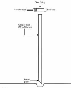
To overcome this problem (see Ill. 2) you can use a garden hose as a 'water drill' to sink the ground rod.
Sweat solder a 'T'-joint on the top end of the pipe, and then sweat solder a faucet or spigot fitting that matches the garden hose end on one end of the 'T'-joint. Cap off the other port of the 'tee'-joint. Use the 'tee'-joint as a handle to drive the pipe into the ground. When water pressure is applied, the pipe will sink slowly into the ground as you apply a downward pressure on the tee-handle. In some cases, the pipe will slip into the ground easily, requiring only a few minutes. In other cases, where the soil is hard or has a heavy clay content, it will take considerably greater effort and more time.
When you finish the task, turn off the water and remove the garden hose.
Some people also recommend unsoldering and removing the 'T'-joint.
Ill. 2
ALTERING SOIL CONDUCTIVITY
The conductivity of the soil determines how well, or how poorly, it conducts electrical current (Tbl 1). Moist soil over a brackish water dome con ducts best. In the USA, the southern swamps make better radio station locations than most of the rest of the country; and the sand of the western deserts make the worst.
In Arizona, for example, one finds that few buildings have cellars or basements. The reason is that there is a thick calcium-based layer (called 'caleche') a meter or two down that resists even mechanized diggers. To build homes in that sand they have to drill holes in the caleche and then sink pylons down to bedrock.
The same caleche also prevents water from sinking into the sand, so it flows off the land in natural channels in the desert. The area is rather dangerous for out-of-state campers who don't understand that those nice ?at, areas at the bottom of gulleys have a habit of filling in seconds if there is a distant thunder storm in the mountains. They look up, and to their horror see a 3-5m high wall of water rushing toward them at 50 km/h! During the late summer months, Arizona has a 'monsoon' season when it rains hard and floods every day (90% of the state's annual rainfall comes in a 6-week period from sometime in July to mid-September). Evaporation is so rapid that an hour after the rain stops, there is little evidence of the rainfall except in the gulleys. If you have never felt hot rain, then visit southern Arizona in August -- but be prepared for temperatures around 438C in the shade and 808C on the front seat of an automobile if you are so unwise as to leave all the windows rolled up.
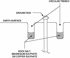
Ill. 3 shows a method for reducing the soil electrical resistance by treating with one of three chemicals: copper sulfate, magnesium sulfate or common rock salt. Rock salt is one of several salt materials used for snow and ice melting in snow-prone areas. If you can't locate rock salt in a hardware store, then look for a store that sells ice cream making supplies.
Rock salt is a principal ingredient in the process (but not the product).
Tbl 1 Type of soil:
Salt water Fresh water Pastoral hills Marshy, wooded Rocky hills Sandy Cities
Dielectric constant: 81 80 14-20 12 12-14 10 3-5
Conductivity (siemans/m):
5
0.001
0.03-0.01
0.0075
10
0.002
0.001
Relative quality:
Best
Very poor
Very good
Average/poor
Poor
Poor
Very poor
Ill. 3A shows a side sectioned view of a circular slit trench method of applying the chemical treatment to reduce ground resistance.
WARNING: before using this method, you need to determine whether or not you really want to do it. The method involves putting conductive chemicals into the ground. Make sure that local, state or national environmental regulations don't prohibit the practice. Also, if you ever want to use the spot to grow vegetables or flowers - or even grass - it will prove difficult because the chemicals essentially poison the soil for several years. Fortunately, they are water-soluble, so the effect will not last forever.
Dig a 15-30 cm deep circular trench, about 30-60 cm from the ground rod. Fill that trench with a 10-12 cm layer of rock salt, magnesium sulfate, or copper sulfate (use only one). Water the trench well for about 15 minutes.
Cover the remaining depth with soil removed when you have dug the trench.
If you use about 100 kg of material, the treatment will need to be repeated every 24-36 months, depending upon the local rainfall and soil composition.
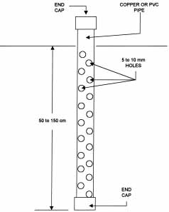
Ill. 3B shows an alternative method: the salt pipe. Use either cop per or PVC plumbing pipe, up to 10 cm in diameter (although 4-8 cm is easier to work). The overall length of the pipe should be at least 50-150 cm.
Although longer pipes are useful, they are also difficult to install. Drill a large number of small holes in the pipe (no hole over 10 mm), sparing only the end that will be above the surface. Cap off both ends.
Install several saltpipes in a pattern around the ground rod. Installation is best accomplished using a fencepost hole digger. Drop the saltpipe into the hole and backfill with water. Remove the top end-cap and hose down for about 15 minutes, or until all the material is gone. Refill the pipe occasion ally to account for the salt leaching out. When the chemical is completely leeched out of the pipe, refill the pipe and recap the top end. Leave the pipe in place.
Be certain of local environmental laws before using the above methods.
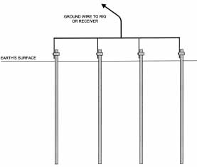
MULTIPLE GROUND RODS
The key to a low-resistance ground is the surface area in contact with the soil. One means for gaining surface area, and thereby reducing ground resistance, is to use multiple ground rods. Ill. 4 shows the use of four ground rods in the same system. The rods are placed 30-100 cm apart for low- and medium-power levels, and perhaps more than 100 cm for higher amateur radio power levels. An electrical connection is made between the rods on the surface using either copper stripping or copper braid. The connections are sweat soldered in the manner described above, with the feed point at the center rod.
Ill. 4
Ill. 5
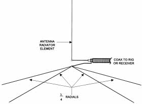
RADIALS AND COUNTERPOISE GROUNDS
The effectiveness of the ground system is enhanced substantially by the use of radials either above ground, on the surface, or buried under the surface.
Ill. 5 shows a vertical antenna with a set of ground radials. It is not unreasonable to use both radials and a ground rod. Vertical antennas are relatively ineffective unless provided with a good ground system, and for most installations that requirement is best met through a system of ground radials.
An effective system of radials requires a large number of radials.
Although as few as two quarter-wavelength resonant radials will provide a significant improvement, the best performance is to use more.
Broadcasters in the AM band (550-1640 kHz) are advised to use 120 half wavelength radials. Installing more than 120 radials is both expensive and time-consuming, but does not provide any substantial improvement. For amateur and small commercial stations, a minimum of 16 quarter-wave length radials should be used. Above ground, the use of insulated wire is recommended to reduce the possibility of anyone receiving RF burn if it's accidentally touched while transmitting. Although some sources claim that any size wire from AWG 26 up to AWG 10 (SWG 0-12) can be used, it's best to use larger sizes in that range (i.e. AWG 14 through AWG 10 (SWG 16-12)). Either solid or stranded wire can be used.
When viewed from above, the radials should be laid out in a symmetrical pattern around the antenna. This coverage provides both the lowest resistance and the best radiation pattern for the antenna. Solder all radials together at a common point, which might be the ground or mounting rod used to support the vertical antenna.
If your antenna is ground mounted, or if the radials are used with the station ground, then use a system such as that in Ill. 6 to make the connections. A clamp on the ground rod is used to bind together the rod, the radials and the ground wire from the receiver or transmitter. The radials should be buried a few centimeters below the surface. Some people report using the tip of a spade or shovel to dig a very thin trench into which the wire can be pushed. Be careful to get the radial wire deep enough. Ordinary soil dynamics can make the wire rise to the surface within a year or so.
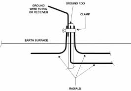
Ill. 6
TUNING THE GROUND WIRE
An alternative that some operators use is the ground wire tuner. These instruments insert a series-tuned inductor-capacitor (LC network) in series with the ground line. These devices are usually called artificial ground tuners, and are inserted into the ground line of the station (Ill. 7). Ground line tuners are especially recommended for cases where the wire to the ground is too long, in the case of single-wire antennas (e.g. Windom antennas or random-length wires), or anytime the tuning seems peculiar, but the antenna tuning unit works well into a dummy load. The purpose of the unit is to tune out any inductive or capacitive reactance on the line. Transmitter operators adjust the ground line tuner for maximum ground current at the operating frequency, although receiver operators will have to experiment a bit to find the correct settings. MFJ Enterprises, makes several such devices. The version shown in Ill. 8 is a stand-alone unit that contains only the ground current meter, inductor, and capacitor. The instrument in Ill. 9 is a combination unit that includes both the ground line tuner and antenna tuner in one box.
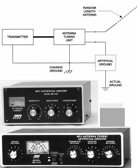
Ill. 7 - Ill. 9
WARNING
Grounds for radio installations are intended for two purposes: making the radio antenna work better and lightning protection. Be absolutely sure to check with local authorities over the minimum requirements for grounding antenna structures - and then doing more than is minimally required. Not only is it possible to get into trouble with the authorities with a poor ground, you may also find that your homeowners and liability insurance is not valid if an uninspected installation is made. My own homeowners policy states that the insurance coverage is not in effect if an antenna is erected that meets the minimum requirements for a mechanical and electrical inspection by the county government but does not have a valid inspection certificate. Check with your local government and insurer before building any antenna or ground system.
Next: