AMAZON multi-meters discounts AMAZON oscilloscope discounts
1. INTRODUCTION
Modern design of an electronic device or electric system requires it to be compatible with its electromagnetic environment, which may contain a number of sources emitting electromagnetic disturbances or noises. The design should be such that these disturbances cause minimum impact on the system performance. Also it’s required that the system-emitted noise(s) in the environment cause minimum impact on the performance of other electronic systems in its vicinity. The entire class of such events can be classified as electromagnetic interference (EMI). In this section we define a few popular terms that are used to describe EMI phenomena and briefly discuss some selected mechanisms by which EMI effects can manifest in an electronic device. This way we can place in proper perspective the interrelationship of applied electromagnetics and electromagnetic compatibility (EMC), which, together, form the subject matter of the present guide.
2. DEFINITIONS
The IEEE Standard Dictionary of Electrical and Electronics Terms [1] defines electromagnetic interference as "impairment of the reception of a wanted electromagnetic signal caused by an electromagnetic disturbance." Electromagnetic disturbances can be in the form of any unwanted electromagnetic signal, including any multipath form of the desired signal. The disturbances can be continuous or discontinuous and repetitive or nonrepetitive in time.
In general, any unwanted electromagnetic signal or disturbance is frequently referred to as noise.
Since the birth of radio communication, the term radio frequency interference (RFI) has been extensively and often erroneously used interchangeably with EMI to describe the interference phenomena. To bring out the subtle difference between the two terms we quote the IEEE definition of RFI: "the impairment of the reception of a wanted radio signal caused by an unwanted radio signal, i.e., a radio disturbance" [1]. We will assume that the range of frequencies of radio signals (or radio frequency) extends from 9 kHz to 3000 GHz, as defined by the Federal Communications Commission (FCC) [2]. Thus RFI can be described as the impairment of the reception of wanted signal caused by a radio frequency disturbance.
The existence of ambient noise in the environment makes it necessary that proper considerations be given during the initial design phase of an electronic device so that the device is immune (not susceptible) to performance degradation due to interaction with a pre-assigned minimum level of such electromagnetic noise. At the same time, it’s also important to ensure that the system does not emit electromagnetic noise above some pre-assigned level so as not to cause performance degradation of other electronic systems in its vicinity. In addition considerations must be given so that system generated internal noise does not interfere with itself, thereby degrading the system's performance.
With the proliferation of a large variety of electronic systems (particularly digital devices, which are efficient radiators of electromagnetic energy), the design of such systems in modem time attempts to fulfill these requirements so that the system designed is compatible with the ambient electromagnetic environment.
We define electromagnetic compatibility (EMC) as "the capability of electromagnetic equipments or systems to be operated in the intended operational electromagnetic environment at designated levels of efficiency" [1]. In the United States these levels are generally assigned by the FCC. They will be described in a later section.
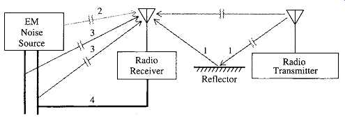
FIG. 1 Identifying selected noise paths to the receiver. A radio receiver
in free space receiving signals from a distant transmitter.
3. INTERFERENCE MECHANISMS
A system may suffer performance degradation due to EMI in a variety of ways. For illustration, we consider a simple case of a radio receiver receiving the desired signal from a distant transmitter (source) in free space shown in FIG. 1. For simplicity we have assumed only one isolated electromagnetic noise source, and a simple reflector (of the desired signal) acting as a multipath source in the vicinity of the radio receiver.
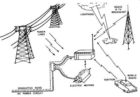
FIG. 2 Outside of the laboratory, electronic equipment such as this radio
is subject to a variety of electromagnetic noise sources. Careful design
is required to guarantee compatibility with the environment.
Ideally, only the direct signal should be received by the radio receiver. Unwanted electromagnetic disturbances can also reach the receiver by a selected number of paths, as shown in FIG. 1. The four paths indicate the following five electromagnetic disturbances received by the receiver in addition to the desired signal:
1. The multipath signal reaches the receiver through path 1. The signal is similar to the desired signal but reaches the receiver after suffering a reflection off the reflector. Often the amplitude is approximately the same as that of the desired signal but the phase is different at the receiving antenna. The magnitude of this phase difference generally determines the amount of corruption in the reception.
2. Disturbances radiated from the noise source reach the receiver by path 2.
3. A variety of electrical disturbances exist in the power line. Also the EM noise source may introduce noise by conduction into the power line.
Path 3 shows the total noise in the power line reaching the receiver by radiation.
4. The EM noise source can conductively couple noise into its signal or control cable. This noise can reach the receiver by radiation as shown by path 3.
5. Noises in the power line can reach the receiver by conductive coupling, path 4. It’s assumed that the radio receiver and the EM noise source have a common power supply.
A more realistic illustration, taken from [3], is shown in FIG. 2. From the two cases given in FIG. 1 and 2 it’s observed that electromagnetic disturbances can reach a device under consideration through the following three mechanisms: (1) radiation, (2) conduction, and (3) combination of radiation and conduction.
In the examples above we considered the noise existing outside the system.
Within electronic equipment, such as the radio receiver, individual circuit components can interfere with each other in several ways. An example is shown in FIG. 3, taken from [3].
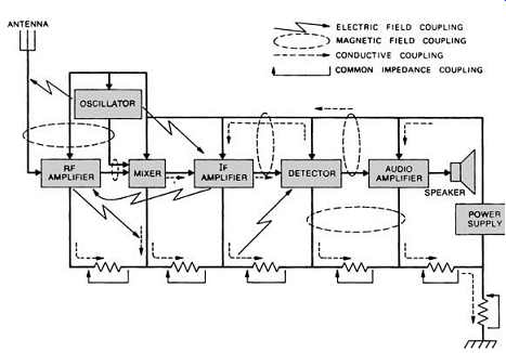
FIG. 3 interfere with one another in several ways. Within equipment,
such as this radio receiver, individual circuit elements can
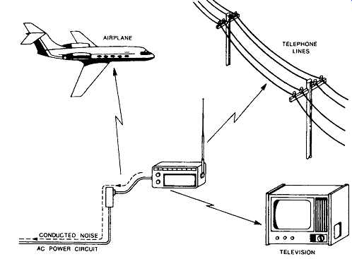
FIG. 4 Electronic equipment such as this radio can emit noise that may
interfere with their circuits. Consideration of noise during equipment
design can avoid these emissions.
======
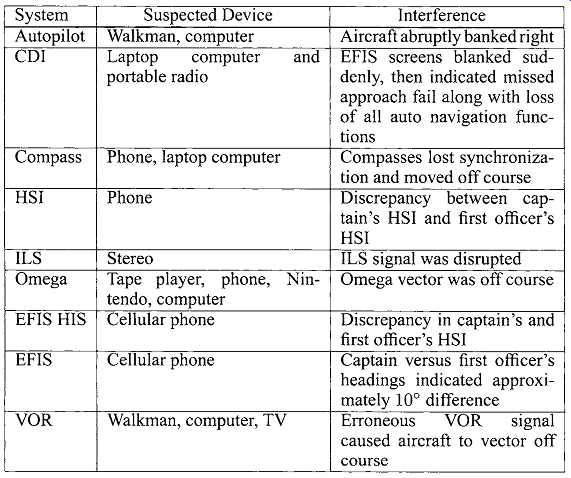
TBL. 1 Examples of Suspected PED-Caused EMI Events System; Autopilot
CDI; Compass HSI ILS Omega EFIS HIS EFIS VOR Suspected Device Walkman,
computer Laptop computer and portable radio; laptop computer; SmartPhone;
Stereo Tape player, phone, Nintendo, computer Cellular phone Cellular phone
Walkman, computer, TV Interference Aircraft abruptly banked right EFIS
screens blanked suddenly, then indicated missed approach fail along with
loss of all auto navigation functions Compasses lost synchronization and
moved off course Discrepancy between captain's HSI and first officer's
HSI ILS signal was disrupted Omega vector was off course; Discrepancy in
captain's and first officer's HSI Captain versus first officer's headings
indicated approximately 10" difference Erroneous VOR signal caused
aircraft to vector off course
======
It’s also important that the system, in this case the radio receiver, not behave as a source of noise capable of interfering with other equipment in its vicinity, as depicted in FIG. 4, taken from [3]. Here again, radiative and conductive coupling as well as a combination of both can cause undesirable interference.
4. EXAMPLES
Examples of malfunction suffered by electronic devices of various kinds due to EMI effects caused by a variety of other electronic systems have been reported and discussed in technical journals, trade journals, and even in newspapers.
Such events are also briefly discussed in technical guides.
Here we give a sampling of such events suffered by some aircraft navigation equipment suspected to be caused by airborne operation of portable electronic devices (PEDs) [7]. Typically PEDs operate from very low frequencies to thousands of MHz. The active electronic/electric components of these mostly digital PEDs emit frequencies, usually with harmonics, that can overlap with the operating frequencies of the communication and navigation systems of the airplane. Thus navigation and other electronic systems of the airplane may be susceptible to performance degradation due to the EMI effects of passenger-carried PEDs if they radiate emission levels above the sensitivity levels of the airplane systems. TBL. 1, taken from [7], gives a sampling of suspected cases of PED interference, along with the systems affected and the suspect device causing the malfunction.
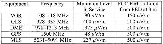 TBL. 2 shows that the emission levels of some FCC-certified PEDs exceed
the sensitivities of some operating avionic systems, thereby causing malfunction
of the latter. Further discussion of the EMI effects of PEDs is given in
[7].
TBL. 2 shows that the emission levels of some FCC-certified PEDs exceed
the sensitivities of some operating avionic systems, thereby causing malfunction
of the latter. Further discussion of the EMI effects of PEDs is given in
[7].
5. DISCUSSION
An electronic system is compatible with its electromagnetic environment if it satisfies the following two criteria: it does not emit (unintentional) electromagnetic energy above a certain minimum level, and it’s not susceptible to malfunction if unintentional electromagnetic energy below a certain level is incident on it. Design of electronic devices from the EMC considerations above requires understanding of electromagnetic fields and waves and their application to a variety of problems.